Advertisement
Quick Links
Advertisement

Related Manuals for GRAYHILL 3D50 Series


Summary of Contents for GRAYHILL 3D50 Series
- Page 1 Series 3D50 Development Kit Quick Start Guide Bulletin 1250 rev.0817...
-
Page 2: Revision History
Revision History Revision Date Description 12/16/2015 Original Release 03/07/2016 Added USB to CAN adapter to equipment list 04/28/2016 Added Appendix A. 08/30/2017 Minor corrections 3D50 Dev Kit – Quick Start Guide Bulletin 1250 rev.0817... -
Page 3: Hardware Setup Instructions
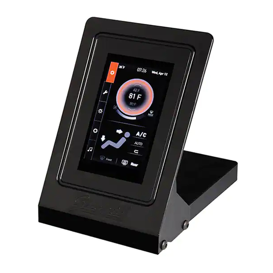
Introduction These instructions describe how to connect the 3D50 Display to its development board and how to connect the power, Ethernet, CAN bus, and RS-232 serial bus. Equipment from Grayhill Included with 3D50Dev-100 Kit 3D50VT-100 Display 3D50 Mounting Frame ... - Page 4 Connect the 18-pin DT cable to Breakout Board. Be sure to match Pin 1 on the cable to Pin 1 on the Breakout Board. 4. Connect 18-pin DT cable to back of the 3D50 Display. Note that this connector is keyed.
- Page 5 7. Connect DB9 serial cable to Breakout Board COM 1 port. 8. Attach other end of this cable to the serial port on the development PC. 9. Connect the power cable to the Breakout Board. 10. Attach the other DB9 cable to the CAN 1 port on the Breakout Board.
- Page 6 1. Insert the disc or download the software from www.gridconnect.com and install the PCAN USB software. 2. A copy of the Dynamic Link Library (PCANBasic.DLL) provided with the USB PCAN adapter needs to be copied to the Windows PC. It is recommended that the DLL be copied to the same folder as the application (e.g., VUI Builder) that will be using it.
-
Page 7: Power Requirement
Appendix A POWER REQUIREMENT Voltage: 12V Current: 1.5A J6, J7, J9, J10 J2, J3 TYCO PJ-002AH RCJ-014-SMT 747844-6 J1 MAIN CONNECTOR Mating Connector HOUSING: DEUTSCH DT16-18-SA-K004 TERMINAL: DEUTSCH 0462-201-16141 SCHEMATIC 3D50 Dev Kit – Quick Start Guide Bulletin 1250 rev.0817... - Page 8 MAIN CONNECTOR (J1) POWER SWITCHES VBAT (SW1) and VSW (SW2) 3D50 Dev Kit – Quick Start Guide Bulletin 1250 rev.0817...
- Page 9 VIDEO INPUTS CAM1 (J2) and CAM2 (J3) CAN CONNECTORS CAN1 (J6) and CAN2 (J7) RS232 CONNECTOR COM1 (J9) IO CONNECTOR I/O1 (J10) 3D50 Dev Kit – Quick Start Guide Bulletin 1250 rev.0817...
- Page 10 DIP Switch SW3 Leave both switches open (OFF) for normal operation. Closing both switches (ON) connects CAN port 1 to CAN port 2. DIP Switch SW4 Leave all switches open (OFF) for normal operation. Closing switch 1 (ON) connects DIG_IN_1 to IO1 Closing switch 2 (ON) connects IO2 to IO1 Closing switch 3 (ON) connects IO2 to IO3 Closing switch 4 (ON) connects IO4 to IO3...
- Page 11 LEDs D2, D3, D4, D5, and D6 LEDs are illuminated if their corresponding signal is high. 3D50 Dev Kit – Quick Start Guide Bulletin 1250 rev.0817...
Need help?
Do you have a question about the 3D50 Series and is the answer not in the manual?
Questions and answers