Table of Contents
Advertisement
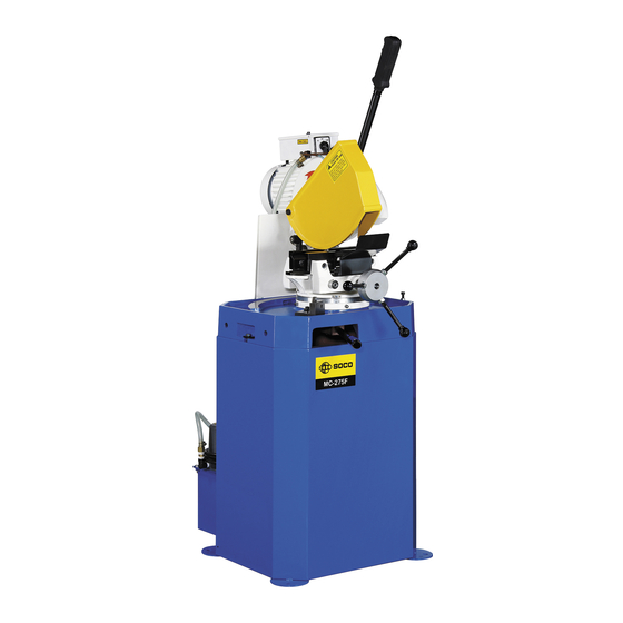
OPERATION INSTRUCTION
FOR
MC-275F
CIRCULAR COLD SAWING MACHINE
SOCO
SOCO MACHINERY CO, LTD.
7, 14th Road, Taichung Industrial Park,
Taichung, Taiwan, R.O.C.
TEL: 886-4-3591888
FAX: 886-4-3592386
http://www.soco.com.tw
E-mail: socomc@tpts7.seed.net.tw
Copyright 2000.6. SOCO Machinery Co. Ltd. All Rights Reserved
1
Advertisement
Table of Contents

Related Manuals for SOCO MC-275F


Summary of Contents for SOCO MC-275F
- Page 1 OPERATION INSTRUCTION MC-275F CIRCULAR COLD SAWING MACHINE SOCO SOCO MACHINERY CO, LTD. 7, 14th Road, Taichung Industrial Park, Taichung, Taiwan, R.O.C. TEL: 886-4-3591888 FAX: 886-4-3592386 http://www.soco.com.tw E-mail: socomc@tpts7.seed.net.tw Copyright 2000.6. SOCO Machinery Co. Ltd. All Rights Reserved...
-
Page 2: Table Of Contents
CONTENTS 1. SAFETY PRECAUTION-----------------------------------------------------------3 2. SPECIFICATIONS AND OUTLINE DRAWING-------------------------------4 2.1 Technical Data 2.2 Cutting Capacity 2.3 Accessory 2.4 Outline Description 3. INSTRUCTION OF INSTALLATION-------------------------------------------8 3.1 Unpacking and Inspection 3.2 Lifting, Moving and Anchoring 3.3 Connecting Electric Power 3.4 Filling coolant 3.5 Procedure to install the stopper 4. -
Page 3: Safety Precaution
1. SAFETY PRECAUTION (1) Operator of the machine shall read the operation instruction carefully and understand the safety requirement and the function of all parts of machine thoroughly. (2) Only the authorized and dedicated operators are allowed to operate the machine. (3) The machine is designed and manufactured to meet the applicable safety regulation of your country. -
Page 4: Specifications And Outline Drawing
HIGH SPEED STEEL BLADE SAW BLADE SIZE OD: 250/275 mm COOLING PUMP 1/8 HP AIR PRESSURE WEIGHT 200 KG 2.2 Cutting Capacity MC-275F CUTTING CAPACITY(USE φ275 BLADE) mm CUTTING ANGLE FOR MILD STEEL 90° 45° φ80 φ60 ROUND TUBE SQUARE TUBE 75×75... -
Page 5: Outline Description
2.4 Outline Description (1) Front View... - Page 6 (2) Right Side View...
- Page 7 (3) Left Side View...
-
Page 8: Instruction Of Installation
3. INSTRUCTION OF INSTALLATION Note: Please read the instruction carefully before installation. If having any question please contact your dealer for prompt service. 3.1 Unpacking and Inspection (1) Check if there is any damage on the wooden case or the plastic bag that used to pack the machine. -
Page 9: Filling Coolant
(3) Check the rotation of the saw blade shaft (arbor). Change over two conductors in junction box if the direction of rotation does not consist with the direction of the label on the saw blade safety cover. 3.4 Filling coolant (1) Pour the diluted sawing oil on the table of the machine. -
Page 10: Function Of Control Devises
4. FUNCTION OF CONTROL SWITCHES (1) Trigger Switch This is an "ON-OFF" two-position trigger switch on the handle to connect or disconnect power to the machine. The main (saw blade) motor and coolant motor run when this switch is pressed. The above motors stop when this switch is released. (2) Saw Blade Motor Speed Select Switch This is a "LOW-OFF-HI"... -
Page 11: Instruction Of Operation
5. INSTRUCTION OF OPERATION 5.1 Preparation for Operation 5.1.1 Adjustment of the Clamping Vise (1) Release the handle. (Cutting head shall be at up position) (Saw blade motor shall stop.) (2) Turn the vise hand wheel counter-clockwise to open the vise. (3) Put a work piece into the clamping area of vises. -
Page 12: Adjustment Of Saw Blade Low Stop Position
Diameter 0.8~1.0 D≧10 mm 1.0~1.2 1.2~1.6 1.6~2.0 2.0~2.5 D≧15 mm 2.5~3.5 D≧20 mm 3.5~4.5 D≧25 mm 4.5~5.5 D≧30 mm 5.5~7.0 D≧40 mm For Wall Thickness≧2 mm, the Formula for Number of Tooth T is as following T= 2×(Diameter of Saw Blade×3.14)÷(Wall Thickness of Tube) Number of Saw Blade Tooth (T) for Mild Steel Solid Bar Cutting Size of Bar Diameter of Saw Blade ( mm ) -
Page 13: Steps Of Operation
(1) Push the turning table fixing handle leftward. (2) Turn the turning table to the required angle. (3) Push the fixing handle rightward. 5.2 Steps of Operation (1) Prepare the machine as states in Section 5.1. (2) Put a work piece into vise. (3) Turn the vise hand wheel clockwise to clamp the work piece. -
Page 14: Parts Drawing And List
7. PARTS DRAWING AND LIST (1) Head and Spindle Shaft Assembly (2) Motor Assembly (3) Feeding Handle Assembly (4) Rotary Support Assembly (5) Vise Assembly (6) Table Assembly (7) Saw Blade Protective Cover and Safety Guard Assembly (8) Base Assembly...
Need help?
Do you have a question about the MC-275F and is the answer not in the manual?
Questions and answers