Table of Contents
Advertisement
Quick Links
Advertisement
Table of Contents

Related Manuals for Keysight MX0023A InfiniiMax RC


Summary of Contents for Keysight MX0023A InfiniiMax RC
- Page 1 Keysight MX0023A InfiniiMax RC Probe Amplifier and Probe Heads User’s Guide...
- Page 2 Do not proceed beyond a CAU- tomarily provided to the public. Accordingly, Published by: TION notice until the indicated con- Keysight provides the Software to U.S. gov- Keysight Technologies, Inc. ditions are fully understood and ernment customers under its standard com- 1900 Garden of the Gods Road met.
-
Page 3: Table Of Contents
Contents 1 MX0023A Probe Amplifier - Overview Introduction MX0023A Key Features Compatibility with Keysight Oscilloscopes 2 Available Probe Heads and Accessories - Overview Introduction to Supported Probe Heads When to Use Which Probe Head Other Recommended Accessories and Kits N5450B Extreme Temperature Cable Extension Kit... - Page 4 Velcro Pads Tips for Soldering Probe Heads Cleaning 5 Characteristics and Specifications MX0023A Probe Amplifier Warranted Specifications MX0023A Probe Amplifier Characteristics InfiniiMax RC Probe Heads Characteristics Environmental and General Characteristics 6 MX0100A InfiniiMax Micro Probe Head Overview MX0100A Probe Head Kit Components MX0100A Dimensions MX0100A Input Impedance Setting up and Using the MX0100A Probe Head...
- Page 5 Adjusting Spacing Between the Browser Tips Hands-Free Probing Maintaining the N2839A Probe Head N2839A Probe Head Handling Precautions Location of Serial Number Replacing the Browser’s Tips 9 MX0105A InfiniiMax Differential SMA Probe Head Overview MX0105A Probe Head Components MX0105A Dimensions MX0105A SPICE Subcircuit Data MX0105A Input Return Loss (S11) 10 N5425B InfiniiMax Differential ZIF Probe Head...
- Page 6 13 InfiniiMax RC Probe Amplifier and Probe Heads System Responses Typical Corrected System Frequency Response Typical Step Response of Corrected System Typical CMRR 14 Returning a Probe/Probe Head for Repair/Service Contacting Keysight Technologies for Technical Assistance 15 Replacement Parts MX0100A Probe Head MX0106A Probe Head N2839A Browser Head...
-
Page 7: Mx0023A Probe Amplifier - Overview
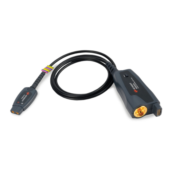
Keysight InfiniiMax RC Probe Amplifier and Probe Heads User’s Guide MX0023A Probe Amplifier - Overview Introduction MX0023A Key Features Compatibility with Keysight Oscilloscopes... - Page 8 MX0023A Probe Amplifier - Overview Introduction The MX0023A InfiniiMax RC probe amplifier provides high bandwidth of up to 25 GHz and an RC input impedance profile for extremely low mid-band loading, which is necessary to address modern high-speed probing requirements.
- Page 9 MX0023A Probe Amplifier - Overview Table 1 MX0023A Probe Amplifier Components Probe Amplifier Component Description/Usage Channel Identification Rings When multiple probes are connected to the oscilloscope, use the channel identification rings to associate the channel inputs with each probe. Place one colored ring near the probe’s output connector and place an identical color ring near the probe head connector.
- Page 10 MX0023A Probe Amplifier - Overview MX0023A Key Features Yielding Accurate The MX0023A probe amplifier has built-in probe specific s-parameter correction Measurements filter to ensure a flat frequency response. This unique s-parameter of the probe amplifier is used with the s-parameters of various supported probe heads to further flatten the magnitude and phase response of the probe for high accuracy measurements.
- Page 11 N OT E Series, InfiniiVision, or any previous generation Keysight oscilloscopes. Is your oscilloscope software up-to-date? Keysight periodically releases software updates to support your probe, fix known defects, and incorporate product enhancements. To download the latest firmware, go to www.Keysight.com search for your oscilloscope’s model number.
- Page 12 MX0023A Probe Amplifier - Overview InfiniiMax RC Probe Amplifier and Probe Heads User’s Guide...
- Page 13 Keysight InfiniiMax RC Probe Amplifier and Probe Heads User’s Guide Available Probe Heads and Accessories - Overview Introduction to Supported Probe Heads When to Use Which Probe Head Other Recommended Accessories and Kits N5450B Extreme Temperature Cable Extension Kit N2880A InfiniiMax In-Line Attenuator Kit...
-
Page 14: Available Probe Heads And Accessories - Overview
(supporting bandwidths up to 12 GHz) Figure 2 on page 15). Detailed information on each of these probe heads is available in the Keysight 1168/9B-Series Differential and Single-Ended Probes user’s guide. This guide is available for download from the Document Library tab on www.keysight.com/find/1169B. - Page 15 Available Probe Heads and Accessories - Overview Figure 2 MX0023A Probe Family Diagram InfiniiMax RC Probe Amplifier and Probe Heads User’s Guide...
-
Page 16: When To Use Which Probe Head
Available Probe Heads and Accessories - Overview When to Use Which Probe Head The following table provides a high-level comparison of the supported probe heads to help you assess when to use which probe head with MX0023A. These probe heads are listed in the order of their maximum supported bandwidth when used with the MX0023A probe amplifier. - Page 17 Available Probe Heads and Accessories - Overview Table 2 Supported Probe Heads (Sheet 2 of 3) Cdiff Probe Head (listed in the order of BW) Recommended Usage Bandwidth (pF) (pF) 5. N5425B Differential ZIF Probe Head (refer to page 99 for details) •...
- Page 18 Available Probe Heads and Accessories - Overview Table 2 Supported Probe Heads (Sheet 3 of 3) Cdiff Probe Head (listed in the order of BW) Recommended Usage Bandwidth (pF) (pF) 8. N5425B ZIF Probe Head with Long Wire ZIF Tips (refer to 1168/9B-Series Probes user’s guide) •...
-
Page 19: Other Recommended Accessories And Kits
Available Probe Heads and Accessories - Overview Other Recommended Accessories and Kits In addition to the probe heads listed in the previous section, there are a number of kits and accessories available for use with the MX0023A probe amplifier. This section provides an overview to these recommended accessories and kits. You can either order these at the time of ordering the probe amplifier or separately later. -
Page 20: N2881A Infiniimax Dc Blocking Capacitors
Available Probe Heads and Accessories - Overview Table 4 N2880A Kit Contents Item Qty Supplied Description 6 dB Attenuators These attenuators come as matched pairs and should only be used with each other. Each attenuator has a serial number. 12 dB Attenuators The pair of matching attenuators in each set will have the same four digit numeric prefix and will differ by the last letter 20 dB Attenuators... - Page 21 Available Probe Heads and Accessories - Overview Double-sided Foam Tape Regular Solder Wire Low Temperature Solder Wire Cutting Tweezers Straight Tweezers Probe Tip Wire Kapton Tape Figure 5 MX0102A soldering toolkit contents InfiniiMax RC Probe Amplifier and Probe Heads User’s Guide...
- Page 22 Available Probe Heads and Accessories - Overview Table 5 Accessories supplied in the soldering toolkit Part Description Supplied Number Straight Tweezers 8710-2837 (Anti-magnetic straight pointed tip 120mm) For general purpose manipulation / movement of com- ponents such as probe tip wires and probe head. Cutting Tweezers 8710-2838 (Narrow oblique head 115mm)
-
Page 23: N2852A Autoprobe Ii To Autoprobe Iii Adapter
N2852A AutoProbe II to AutoProbe III Adapter This adapter allows you to connect the MX0023A probe amplifier that has the AutoProbe II interface to the Keysight UXR-Series (40GHz or higher) Infiniium oscilloscope that has the AutoProbe III interface. To know more about the N2852A adapter, visit http://www.keysight.com/find/N2852A... -
Page 24: N5448B (25Cm) / N2823A (1M) Coaxial Phase Matched Cable Pair
5 psec, and the cable supports up to 40 GHz. For detailed specifications of these cables, refer to the user’s guide available in the Document Library tab of www.keysight.com/find/N5448B. Figure 6 N2823A and N5448B Coaxial Phased Matched Cable Pairs The maximum bend radius for these coaxial cable pairs is 30 mm. -
Page 25: E2669B Differential Connectivity Kit
Available Probe Heads and Accessories - Overview E2669B Differential Connectivity Kit The E2669B differential connectivity kit provides multiple quantities of the: • following three InfiniiMax I probe heads supported for use with the MX0023A probe amplifier. • accessories needed for these three probe heads. Figure 7 E2669B Differential Connectivity Kit (not to scale) InfiniiMax RC Probe Amplifier and Probe Heads User’s Guide... - Page 26 Available Probe Heads and Accessories - Overview Table 8 E2669B Kit Contents Probe Heads Included in the Kit Supplied E2678B Differential Socketed Head E2677B Differential Solder-In Head E2675B Differential Browser Used With Part Number Other Accessories Included in the Kit Supplied E2678B E2677B...
-
Page 27: Safety And Regulatory Information
Keysight InfiniiMax RC Probe Amplifier and Probe Heads User’s Guide Safety and Regulatory Information Safety Checks and Warnings Instrument Markings and Symbols... -
Page 28: Safety Checks And Warnings
Periodically inspect the probe and probe wires to check for any damage. WARNING Do Not Operate With Visible or Suspected Failures. If you suspect there is damage, have it inspected by a Keysight authorized service personnel. InfiniiMax RC Probe Amplifier and Probe Heads User’s Guide... - Page 29 Do not install substitute parts or perform any unauthorized modification to the probe WARNING amplifier / probe head. Do not attempt internal service or adjustment. Service should be carried out by a Keysight Technologies authorized service personnel. For any service needs, contact Keysight Technologies. See page 149 to know more.
- Page 30 Instrumentation” product. Do not dispose in domestic household waste. To return unwanted products, contact your local Keysight office. This symbol indicates that it is necessary for you to follow the instructions in the user’s guide to protect against damage to the product or personal injury.
-
Page 31: Proper Handling Of Probe Amplifier And Probe Heads
Keysight InfiniiMax RC Probe Amplifier and Probe Heads User’s Guide Proper Handling of Probe Amplifier and Probe Heads Avoiding Damage and Costly Repairs Using a static-safe workstation Probe Amplifier and Probe Heads Handling Precautions Precautions while Connecting and Disconnecting Probe Heads... -
Page 32: Avoiding Damage And Costly Repairs
Proper Handling of Probe Amplifier and Probe Heads Avoiding Damage and Costly Repairs Using a static-safe workstation InfiniiMax RC probes and accessories are ESD sensitive devices. Before using or handling any of these, always wear a grounded ESD wrist strap and ensure that cables and probe heads are discharged before being connected. - Page 33 Proper Handling of Probe Amplifier and Probe Heads Figure 9 Wrist Strap Connected to Oscilloscope’s Ground Socket These techniques for a static-safe workstation should not be WARNING used when working on circuitry with a voltage potential greater than 500 volts. InfiniiMax RC Probe Amplifier and Probe Heads User’s Guide...
-
Page 34: Probe Amplifier And Probe Heads Handling Precautions
Do not apply excessive force to the probe end and prevent it from CAUTION receiving mechanical shock. This damage is considered to be abuse and will void the warranty when verified by Keysight Technologies service professionals. Do not drop heavy objects on the probe, drop the probe from CAUTION large heights, spill liquids on the probe, etc. -
Page 35: Precautions While Connecting And Disconnecting Probe Heads
Proper Handling of Probe Amplifier and Probe Heads Precautions while Connecting and Disconnecting Probe Heads Safely Connecting/Disconnecting the Probe Amplifier and Oscilloscope Always perform the connection in the following sequence: Ground the DUT to the oscilloscope via the AC mains ground or to the oscilloscope ground or to the probe amplifier ground. - Page 36 Proper Handling of Probe Amplifier and Probe Heads • For a solder-in or a ZIF tip probe head, always disconnect the probe head from the amplifier before unsoldering, moving to a new position, and resoldering the probe head. This is because some soldering-iron tips can hold a charge which can damage the probe amplifier.
-
Page 37: Strain Relieving Techniques For Probe Heads
Proper Handling of Probe Amplifier and Probe Heads Strain Relieving Techniques for Probe Heads High-performance probes have small physical geometries to ensure the lowest possible loading and the best electrical response. Because of their small size, probe heads are often delicate. It is important to mechanically secure your probe heads to protect both your equipment and designs from damage. -
Page 38: Tack-Putty
Proper Handling of Probe Amplifier and Probe Heads Tack-putty Wrap a small amount of tack-putty around your probe head cables, taking care to not pinch them. The mass can then be secured to a rigid body near your DUT. Similar techniques can be used to secure probe amplifiers where you apply some tack-putty to the underside of the probe amplifier body and attach it to a rigid body near your DUT. -
Page 39: Velcro Pads
Proper Handling of Probe Amplifier and Probe Heads Velcro Pads The provided Velcro pads can be used to secure your probe amplifier casing to the board. Attach Velcro dots to the probe amplifier as well as the circuit board as shown in the figure below. -
Page 40: Tips For Soldering Probe Heads
• Apply enough flux to probe head leads and wires when soldering the tips into a DUT. See Also • Soldering Guidelines for Keysight InfiniiMax Probes Application Note (publication number 5992-3350EN) • “Soldering an MX0100A Probe Head to DUT" on page 57 •... -
Page 41: Cleaning
Proper Handling of Probe Amplifier and Probe Heads Cleaning If the probe amplifier or probe head requires cleaning: Disconnect the probe head from the probe amplifier. Disconnect the probe amplifier from the oscilloscope. Disconnect the probe head from any circuit under test. Gently clean the probe amplifier /probe head with a soft cloth dampened with a mild soap and water solution. - Page 42 Proper Handling of Probe Amplifier and Probe Heads InfiniiMax RC Probe Amplifier and Probe Heads User’s Guide...
-
Page 43: Characteristics And Specifications
Keysight InfiniiMax RC Probe Amplifier and Probe Heads User’s Guide Characteristics and Specifications MX0023A Probe Amplifier Warranted Specifications MX0023A Probe Amplifier Characteristics InfiniiMax RC Probe Heads Characteristics Environmental and General Characteristics The tables in this chapter list the specifications and characteristics for the MX0023A probe amplifier and its supported probe heads. -
Page 44: Mx0023A Probe Amplifier Warranted Specifications
Characteristics and Specifications MX0023A Probe Amplifier Warranted Specifications Table 9 Warranted Specifications Probe Amplifier Probe Head Specification MX0023A 25 GHz MX0100A Micro Bandwidth 25 GHz (with 60 mil leads) Probe Amplifier Probe Head DC Input = 50 kW ±2% diff Resistance = 25 kW ±2% InfiniiMax RC Probe Amplifier and Probe Heads User’s Guide... -
Page 45: Mx0023A Probe Amplifier Characteristics
Characteristics and Specifications MX0023A Probe Amplifier Characteristics The characteristics listed in the following table are mainly determined by the probe amplifier. Characteristic MX0023A Probe Amplifier With 25kW Probe Heads With MX0105A SMA Probe Head (MX0100A, MX0106A, N2839A, MX0105A, N5425B, N5381B) DC Input Resistance = 25 kW ±... - Page 46 Characteristics and Specifications Characteristic MX0023A Probe Amplifier With 25kW Probe Heads With MX0105A SMA Probe Head (MX0100A, MX0106A, N2839A, MX0105A, N5425B, N5381B) Maximum Non-destructive 30 V mains isolated See maximum input power peak Input Voltage a Delay can be skewed relative to other signals. b Mains isolated is for measurements performed on circuits not directly connected to a mains supply.
-
Page 47: Infiniimax Rc Probe Heads Characteristics
For information on the characteristics and specifications for the following N OT E InfiniiMax I and II probe heads that are compatible for use with the MX0023A probe amplifier, refer to the Keysight 1168/9B-Series Differential and Single-Ended Probes user’s guide. Visit www.keysight.com/find/1169B to download this guide. -
Page 48: Environmental And General Characteristics
Characteristics and Specifications Environmental and General Characteristics Table 11 Environmental and General Characteristics of MX0023A amplifier and InfiniiMax RC Probe Heads Environmental Condition Operating Non-Operating Temperature +5 °C to +40 °C –40 °C to +70 °C Humidity up to 95% relative humidity up to 90% relative humidity at +65 °C (non-condensing) at +40 °C... -
Page 49: Mx0100A Infiniimax Micro Probe Head
Keysight InfiniiMax RC Probe Amplifier and Probe Heads User’s Guide MX0100A InfiniiMax Micro Probe Head Overview MX0100A Probe Head Kit Components MX0100A Dimensions MX0100A Input Impedance Setting up and Using the MX0100A Probe Head Trimming the Lead Wires of MX0100A Probe Head... -
Page 50: Overview
MX0100A InfiniiMax Micro Probe Head Overview The MX0100A is a solder-in head designed to access small geometry target devices. The probe head is made out of flex printed circuit, making it light, flexible, small yet highly usable. It provides up to 25 GHz of full probe amplifier bandwidth when used with the MX0023A and excellent probe loading characteristic (170 fF). -
Page 51: Mx0100A Probe Head Kit Components
MX0100A InfiniiMax Micro Probe Head When probing differential signals, the + and – connection of the N OT E MX0100A probe head can be determined when the probe head is plugged into the probe amplifier. The + and - indicators on the probe amplifier represent the + and - inputs on MX0100A probe head. - Page 52 MX0100A InfiniiMax Micro Probe Head Figure 17 MX0100A Probe Head Dimensions InfiniiMax RC Probe Amplifier and Probe Heads User’s Guide...
-
Page 53: Mx0100A Input Impedance
MX0100A InfiniiMax Micro Probe Head MX0100A Input Impedance Input impedance is a function of the probe head only. The probe amplifier N OT E bandwidth (25 GHz) does not have any effect on the input impedance of the probe head. This section provides: •... - Page 54 MX0100A InfiniiMax Micro Probe Head MX0100A SPICE Model The following SPICE model can be used to predict the probe loading effects of the InfiniiMax RC probe and MX0100A probe head combination. Figure 18 SPICE Model for the input impedance of the MX0100A Micro Probe Head InfiniiMax RC Probe Amplifier and Probe Heads User’s Guide...
- Page 55 MX0100A InfiniiMax Micro Probe Head SPICE Deck and Measured/Modeled Data Matching .subckt MX0100A 1 2 RTipP 1 3 11.58 RTipM 2 4 11.58 C1 3 5 48.86f L1 5 6 24.79n R1 6 4 1.589k Rp1 7 3 88.3 Lp1 8 7 .845n Cp1 11 8 .223p Rm1 4 9 88.3 Lm1 9 10 .845n...
-
Page 56: Setting Up And Using The Mx0100A Probe Head
The s parameter file adjusts the frequency response to enhance the measurements accuracy. To properly trim the probe head’s lead wires Use the Keysight supplied trim gauge template that is included as part of the MX0100A probe head kit. Figure 20 MX0100A Trim Gauge Template (MX0100-94302) Using tweezers, place the lead wire over the outline of the lead wires as shown on the trim gauge template. -
Page 57: Soldering An Mx0100A Probe Head To Dut
Trim the length of the MX0100A probe head lead wires to match your DUT’s geometry (see page 56). You may use the cutting tweezers (Keysight part number 8710-2838) included in the Soldering toolkit. Apply flux to both DUT and MX0100A probe tip lead wires. Always use plenty of flux, even if your solder already contains flux. - Page 58 - Do not rest a soldering iron on a probe joint for more than a few seconds. Provide strain-relief to the probe head by taping its mid portion to a flat surface such as a tabletop using the double-sided foam tape (such as Keysight part number 0460-3122 included in the MX0102A Soldering Toolkit). You can also use putty, Velcro or low temperature hot glue instead.
- Page 59 MX0100A InfiniiMax Micro Probe Head Provide strain-relief to the probe head and probe amplifier plastic housings by using a double-sided foam tape (Keysight part number 0460-3122 included in the MX0102A Soldering Toolkit).. To view a demo on how to solder the lead wires to the DUT, visit N OT E https://prc.keysight.com/...
-
Page 60: Maintaining The Mx0100A Probe Head
MX0100A InfiniiMax Micro Probe Head Maintaining the MX0100A Probe Head MX0100A Probe Head Handling Precautions One of the advantages of the MX0100A probe head is its reusability feature. This section describes some of the cautions and tips on how to properly handle the MX0100A probe head to prevent damage and maintain high performance and reusability of the probe head. - Page 61 MX0100A InfiniiMax Micro Probe Head Figure 23 Example of incorrect movement of MX0100A probe head • Use a microscope setup while performing soldering/de-soldering tasks. A microscope with the following features is recommended. • Binocular eyepieces • Adjustable magnification (at least 20x) •...
- Page 62 MX0100A InfiniiMax Micro Probe Head To check the MX0100A probe head for any damage You can use a Digital Multimeter to check the resistance measurement of your MX0100A probe head. If the resistance measurement between the probe head’s tip and the center conductor of the SMP connector is ~25.2 kohm, then the probe head is usable.
-
Page 63: Replacing The Mx0100A Probe Tip Lead Wires
MX0100A probe head. Depending on your probing application, you can order either 9 mil or 10 mil solder wire as listed in the following table. These wires are also included in the Keysight MX0102A Soldering Toolkit (see page 20 for details). - Page 64 MX0100A InfiniiMax Micro Probe Head Position the end of the new lead wire (Keysight part number MX0102-21302 or MX0102-21303 included in the MX0102A Soldering Toolkit) over the via hole. Touch the soldering iron to the side of the hole. As the solder in the hole melts down, the lead wire will fall into the hole.
- Page 65 MX0100A InfiniiMax Micro Probe Head Cut the extra wire off using a cutting tweezer (Keysight part number 8710-2838 included in the MX0102A Soldering Toolkit). Remove the Kapton tape. InfiniiMax RC Probe Amplifier and Probe Heads User’s Guide...
-
Page 66: Extreme Temperature Testing With The Mx0100A Probe Head
MX0100A InfiniiMax Micro Probe Head Extreme Temperature Testing with the MX0100A Probe Head The MX0100A probe head can withstand temperatures from –55°C to +150°C thereby making it suitable for extreme temperature environments such as temperature chambers. For extreme temperature testing, use the MX0100A probe head with the N5450B InfiniiMax extreme temperature extension cable. -
Page 67: Mx0106A Infiniimax Differential Solder-In Probe Head
Keysight InfiniiMax RC Probe Amplifier and Probe Heads User’s Guide MX0106A InfiniiMax Differential Solder-in Probe Head Overview MX0106A Probe Head Supplied Accessories MX0106A Dimensions MX0106A Input Impedance Setting up and Using the MX0106A Probe Head Adjusting the Spacing between MX0106A Wires... -
Page 68: Overview
MX0106A InfiniiMax Differential Solder-in Probe Head Overview The MX0106A probe head allows a soldered connection into a system for a reliable hands-free probing. This probe head configuration provides 23 GHz bandwidth and a low capacitive loading for measuring both single-ended and differential signals. - Page 69 MX0106A InfiniiMax Differential Solder-in Probe Head Figure 26 MX0106A Probe Head Dimensions InfiniiMax RC Probe Amplifier and Probe Heads User’s Guide...
-
Page 70: Mx0106A Input Impedance
MX0106A InfiniiMax Differential Solder-in Probe Head MX0106A Input Impedance Input impedance is a function of the probe head only. The probe amplifier N OT E bandwidth (25 GHz) does not have any effect on the input impedance of the probe head. This section provides: •... - Page 71 MX0106A InfiniiMax Differential Solder-in Probe Head MX0106A SPICE Model The following SPICE model can be used to predict the probe loading effects of the InfiniiMax RC probe and MX0106A probe head combination. Figure 27 SPICE Model for the input impedance of the MX0106A Probe Head InfiniiMax RC Probe Amplifier and Probe Heads User’s Guide...
- Page 72 MX0106A InfiniiMax Differential Solder-in Probe Head SPICE Deck and Measured/Modeled Data Matching .subckt MX0106A 1 2 RTipP 1 3 42.1877 RTipM 2 4 42.1877 C1 3 5 11.5513f L1 5 6 4.97914n R1 6 4 10.392k Rp1 7 3 93.7363 Lp1 8 7 .304785n Cp1 11 8 298.107f Rm1 4 9 93.7363...
-
Page 73: Setting Up And Using The Mx0106A Probe Head
MX0106A InfiniiMax Differential Solder-in Probe Head Setting up and Using the MX0106A Probe Head Adjusting the Spacing between MX0106A Wires Figure 29 shows how to adjust the spacing of the probe head’s wires without stressing the solder joint. Use tweezers to grab and stabilize the lead near the pc board CAUTION edge. - Page 74 Rosin flux pencil, RMA type (Kester #186 or equivalent) Flush cutting wire cutters Magnifier or low power microscope Keysight supplied trim gauge (01169-23801) Use the following procedure to install or replace the wire leads of the MX0106A probe head. Use the vise or tweezers clamp to position the tip an inch or so off the work surface for easy access.
- Page 75 MX0106A InfiniiMax Differential Solder-in Probe Head If you need to replace an existing or a damaged wire lead, grab it with tweezers and pull it gently up. Touch the soldering iron to the solder joint just long enough for the wire to come free of the probe head tip. The solder joint has very low thermal mass, so the joint quickly melts and releases the wire.
- Page 76 MX0106A InfiniiMax Differential Solder-in Probe Head Trim Gauge Figure 31 Trim Gauge on Probe Head Cut the wires even with the trim gauge on the side opposite to the probe head. Figure 32 Cutting Wires Flush with Gauge Each wire lead needs to be trimmed to 0.89 mm to fit the hole in the pc board as shown in the following figure.
-
Page 77: Connecting The Mx0106A Probe Head To Dut
MX0106A InfiniiMax Differential Solder-in Probe Head Figure 33 Wire Lead Trim Dimensions Connecting the MX0106A Probe Head to DUT The + and – connection for the MX0106A probe head can be determined N OT E when the probe head is plugged into the probe amplifier. The polarity markings on the probe amplifier represent the + and - inputs on the MX0106A probe head. -
Page 78: Soldering The Mx0106A Probe Head To Dut
MX0106A InfiniiMax Differential Solder-in Probe Head Soldering the MX0106A Probe Head to DUT Always mechanically strain-relieve the probe head to protect your CAUTION probing equipment and DUT from damage. Refer to “Strain Relieving Techniques for Probe Heads" on page 37. Apply flux to your target leads. -
Page 79: Extreme Temperature Testing With The Mx0106A Probe Head
MX0106A InfiniiMax Differential Solder-in Probe Head Extreme Temperature Testing with the MX0106A Probe Head The MX0106A probe head can withstand temperatures from –55°C to +150°C thereby making it suitable for extreme temperature environments such as temperature chambers. For extreme temperature testing, use the MX0106A probe head with the N5450B InfiniiMax extreme temperature extension cable (see page 19). - Page 80 MX0106A InfiniiMax Differential Solder-in Probe Head InfiniiMax RC Probe Amplifier and Probe Heads User’s Guide...
-
Page 81: N2839A Infiniimax Ii Browser Probe Head
Keysight InfiniiMax RC Probe Amplifier and Probe Heads User’s Guide N2839A InfiniiMax II Browser Probe Head Overview N2839A Browser Probe Head Components N2839A Supplied Accessories N2839A Dimensions N2839A Input Impedance Using the N2839A Browser Probe Head Adjusting Spacing Between the Browser Tips... -
Page 82: Overview
The N2839A differential browser is the best choice for signals browsing and general purpose troubleshooting of a circuit board. This probe head supports a bandwidth of 21 GHz when used with the MX0023A InfiniiMax RC probe amplifier. The probe head’s high bandwidth performance, adjustable tips, and ergonomic design makes it ideal for hand held measuring of differential and single-ended signals. - Page 83 N2839A InfiniiMax II Browser Probe Head Accessory Quantity Description Spring-loaded tips Spring-loaded tips are less susceptible to (0.0115 in. diameter, 0.126 in. long) vibration or movement than straight tips and provide more stable spring-loaded contact. Spring-loaded tips work best when these are either partially or fully compressed and are protected against over compression damage.
-
Page 84: N2839A Dimensions
N2839A InfiniiMax II Browser Probe Head N2839A Dimensions N2839A Input Impedance Input impedance is a function of the probe head only. The probe amplifier N OT E bandwidth (25 GHz) does not have any effect on the input impedance of the probe head. - Page 85 N2839A InfiniiMax II Browser Probe Head Refer to the chapter “InfiniiMax RC Probe Amplifier and Probe NOT E Heads System Responses" on page 143 to get a typical corrected frequency response and CMRR for the InfiniiMax RC probe amplifier and probe head combination.
- Page 86 N2839A InfiniiMax II Browser Probe Head SPICE Deck and Measured/Modeled Data Matching * Input impedance SPICE subckt for probe head listed. .subckt N2839A 1 2 r1 1 3 41.09 r2 2 4 41.09 c10 3 17 95.34f c11 4 17 95.34f c1 17 5 100f c7 4 9 100f l1 5 6 8.126n...
- Page 87 N2839A InfiniiMax II Browser Probe Head Figure 36 Input Impedances (Z Modeled and Z Measured) for the N2839A Probe Head InfiniiMax RC Probe Amplifier and Probe Heads User’s Guide...
-
Page 88: Using The N2839A Browser Probe Head
N2839A InfiniiMax II Browser Probe Head Using the N2839A Browser Probe Head Adjusting Spacing Between the Browser Tips The spacing between the N2839A’s tips can be adjusted from 0 mm to 3 mm using the adjustment wheel shown in Figure Figure 37 Adjusting the Tip Spacing The tip span setting does not impact the probe head’s frequency N OT E... - Page 89 N2839A InfiniiMax II Browser Probe Head • or construct a custom holder using the mounting dimensions shown in the following figure. Use a M2 x 4 mm thread screw to attach the probe head. Figure 38 Location and Dimensions of Mounting Hole Do not allow the mounting screw to penetrate more than 4 mm into CAUTION the browser’s mounting hole.
-
Page 90: Maintaining The N2839A Probe Head
N2839A InfiniiMax II Browser Probe Head Maintaining the N2839A Probe Head N2839A Probe Head Handling Precautions This section describes some of the cautions, warnings, and tips on how to properly handle and use the N2839A probe head to prevent damage/injury and maintain high performance and reusability of the probe head. -
Page 91: Replacing The Browser's Tips
N2839A InfiniiMax II Browser Probe Head Figure 39 Location of Serial Number Label Replacing the Browser’s Tips Use the following procedure to install or replace the tips on the N2839A probe head. Replacement tips are supplied with the browser. For additional tips, you can order the N2837A replacement tip kit. - Page 92 N2839A InfiniiMax II Browser Probe Head The probe tip arm can be damaged if too much force is applied CAUTION when inserting the tip. The tip is held in the tip arm by friction and not by a snap or detent connection. Figure 41 Inserting a Tip Hold the probe vertically and gently press the tip on a hard surface, such as the tweezers, to properly seat the tip.
- Page 93 Keysight InfiniiMax RC Probe Amplifier and Probe Heads User’s Guide MX0105A InfiniiMax Differential SMA Probe Head Overview MX0105A Probe Head Components MX0105A Dimensions MX0105A SPICE Subcircuit Data MX0105A Input Return Loss (S11)
-
Page 94: Mx0105A Infiniimax Differential Sma Probe Head
MX0105A InfiniiMax Differential SMA Probe Head Overview The MX0105A SMA probe head allows an easy and a high bandwidth (20 GHz) connection using SMA cables. Unlike coaxial cables that require two oscilloscope channels to measure a differential signal, this probe head requires a single oscilloscope channel to measure a differential signal. - Page 95 SMA cables of the MX0105A probe head with these cables. These cables support 2.92 mm male-to-2.92 mm male connection. For detailed specifications of these cables, refer to the user’s guide available in the Document Library tab of www.keysight.com/find/N5448B. InfiniiMax RC Probe Amplifier and Probe Heads User’s Guide...
-
Page 96: Mx0105A Dimensions
MX0105A InfiniiMax Differential SMA Probe Head MX0105A Dimensions Figure 43 MX0105A Dimensions (All dimensions are in mm[inches]) InfiniiMax RC Probe Amplifier and Probe Heads User’s Guide... -
Page 97: Mx0105A Spice Subcircuit Data
MX0105A InfiniiMax Differential SMA Probe Head MX0105A SPICE Subcircuit Data The MX0105A SMA probe head is modeled by 20 short transmission lines of varying impedance. This accurately models the temporal nature of this probe head. * Input SPICE subckt model for MX0105A .subckt MX0105A 1 t1 1 0 2 0 z0=51.9793 td=15ps t2 2 0 3 0 z0=50.5258 td=15ps... -
Page 98: Mx0105A Input Return Loss (S11)
MX0105A InfiniiMax Differential SMA Probe Head MX0105A Input Return Loss (S11) Input return loss is a function of the probe head only. The probe amplifier N OT E being used does not affect the return loss for the probe head. The graph displayed below therefore does not include the probe amplifier being used. -
Page 99: N5425B Infiniimax Differential Zif Probe Head
Keysight InfiniiMax RC Probe Amplifier and Probe Heads User’s Guide N5425B InfiniiMax Differential ZIF Probe Head Overview Supported ZIF Tips N5425B Probe Head and ZIF Tips Dimensions N5425B Input Impedance Using the N5425B Probe Head with N5426A ZIF Tips Step 1 - Remove N5426A ZIF Tip from Packaging... -
Page 100: Overview
N5425B InfiniiMax Differential ZIF Probe Head Overview The N5425B Zero Insertion Force (ZIF) probe head is the best choice for probing multiple test points in a tight space. The three different types of ZIF tips available for use with this probe head accommodate very small fine pitch targets as well as variable pitch targets, including larger pitches. - Page 101 N5425B InfiniiMax Differential ZIF Probe Head The N5425B probe head supports the following three types of economical replaceable ZIF tips available as orderable kits. The N5426A and N2884A ZIF tips that support high bandwidth (18 GHz) N OT E are described in this user’s guide. For details on the N5451A ZIF tip, refer to the 1168/9B-Series Probes user’s guide.
-
Page 102: N5425B Probe Head And Zif Tips Dimensions
N5425B InfiniiMax Differential ZIF Probe Head N5425B Probe Head and ZIF Tips Dimensions Figure 46 N5425B ZIF Probe Head Dimensions with N5426A ZIF Tip Attached InfiniiMax RC Probe Amplifier and Probe Heads User’s Guide... - Page 103 N5425B InfiniiMax Differential ZIF Probe Head Figure 47 N2884A Fine Wire ZIF Tip Dimensions InfiniiMax RC Probe Amplifier and Probe Heads User’s Guide...
-
Page 104: N5425B Input Impedance
N5425B InfiniiMax Differential ZIF Probe Head N5425B Input Impedance Input impedance is a function of the probe head only. The probe amplifier N OT E bandwidth (25 GHz) does not have any effect on the input impedance of the probe head. This section provides: •... -
Page 105: Spice Model Of N5425B Probe Head With N5426A Zif Tip Attached
N5425B InfiniiMax Differential ZIF Probe Head SPICE Model of N5425B Probe Head with N5426A ZIF Tip Attached 556.5f 40.93f 3.815n 5.731n 38.32 30.4 vplus 64.35 Rtipp AC 1 0 14.75f 6.3f vsplus 1.356n 345.2p Lom2 AC 1 0 vsminus 948.2 36.88 1 RESISTANCE={100e6-(100e6*sw tch-1u)} 64.35... -
Page 106: Spice Deck Of N5425B Probe Head With N5426A Zif Tip Attached
N5425B InfiniiMax Differential ZIF Probe Head SPICE Deck of N5425B Probe Head with N5426A ZIF Tip Attached Lom2 Rom_P 0 2n Lm2 Cm2_N Lm2_N 5.731n Rtipp Rp3_N vplus 64.35 Lm1 Cm1_N Lm1_N 3.815n Rom Rom_P Cp1_P 250 Cp1 Cp1_P Cp1_N 556.5f Cp2 Cp1_P Cp2_N 40.93f Lp1 Cp1_N Lp1_N 3.815n Lp2 Cp2_N Lp2_N 5.731n... - Page 107 N5425B InfiniiMax Differential ZIF Probe Head Cse 0.53pF Cdiff 0.33pF Ω Frequency (H z) Differential (Modeled) Single Ended (Modeled) Single Ended (Measured) Differential (Measured) Figure 49 Measured and Modeled Data Matching for the N5425B Probe Head with N5426A ZIF Tip Attached InfiniiMax RC Probe Amplifier and Probe Heads User’s Guide...
-
Page 108: Spice Model Of The N5426A Zif Tip
N5425B InfiniiMax Differential ZIF Probe Head SPICE Model of the N5426A ZIF Tip 180a 3.1n 3.58n 38.7 23.9 vplus 98.85 Rtipp AC 1 0 3.14f 109.4f vsplus 360p 163.9 9.62n 2.68n Lom2 34.5u AC 1 0 vsminus 451.7 1 RESISTANCE={100e6-(100e6*sw tch-1u)} 98.85 Rsw 1 Rtipm... -
Page 109: Spice Deck Of N5426A Zif Tip
N5425B InfiniiMax Differential ZIF Probe Head SPICE Deck of N5426A ZIF Tip Lom2 Rom_P 0 360p Lm2 Cm2_N Lm2_N 3.58n Rtipp Rp3_N vplus 98.85 Lm1 Cm1_N Lm1_N 3.1n Rom Rom_P Cp1_P 163.9 Cp1 Cp1_P Cp1_N 180a Cp2 Cp1_P Cp2_N 69f Lp1 Cp1_N Lp1_N 3.1n Lp2 Cp2_N Lp2_N 3.58n Cm2 R1_N Cm2_N 69f... - Page 110 N5425B InfiniiMax Differential ZIF Probe Head Ω Frequency (H z) Differential (Modeled) Single Ended (Modeled) Single Ended (Measured) Differential (Measured) Figure 51 Measured and Modeled Data Matching for the N5426A ZIF Tip InfiniiMax RC Probe Amplifier and Probe Heads User’s Guide...
-
Page 111: Using The N5425B Probe Head With N5426A Zif Tips
N5425B InfiniiMax Differential ZIF Probe Head Using the N5425B Probe Head with N5426A ZIF Tips Step 1 - Remove N5426A ZIF Tip from Packaging Before a ZIF tip can be used, you must separate it from its packaging strip. To accomplish this, grab one of the tips with flat nose tweezers and bend it back. - Page 112 N5425B InfiniiMax Differential ZIF Probe Head ZIF tip latch in Closed position Figure 54 ZIF Tip Latch in Closed Position If you are attaching the ZIF tip to the probe head when soldering the tip to DUT, you may need to support the body of the ZIF tip while closing its latch. Use tweezers or other suitable tool to grab the tip’s pc board while the latch is being closed.
- Page 113 N5425B InfiniiMax Differential ZIF Probe Head destroying the ZIF tip. Only the first third of the lead or so needs to be soldered to the target point. Detailed Soldering Procedure Below is an example of installing a ZIF tip to an IC package. The ZIF tip is attached to the first two package leads.
- Page 114 N5425B InfiniiMax Differential ZIF Probe Head Figure 57 Small Amount of Solder Added to Soldering Iron Tip Connect the ZIF tip to the ZIF probe head. This allows the probe head to be used as a handle for the ZIF tip to allow positioning in the DUT. Position the lead wires on the target points and then briefly heat the solder joints.
- Page 115 N5425B InfiniiMax Differential ZIF Probe Head Figure 60 ZIF Tip with ZIF Latch Open InfiniiMax RC Probe Amplifier and Probe Heads User’s Guide...
-
Page 116: Using The N5425B Probe Head With N2884A Fine Wire Zif Tip
N5425B InfiniiMax Differential ZIF Probe Head Using the N5425B Probe Head with N2884A Fine Wire ZIF Tip The procedure required to use the fine wire ZIF tips is very specific. Please read the instructions carefully as each step alerts you to common problem areas and things you need to be aware of when using this tip. - Page 117 You can either order it directly from Wentworth Laboratories (www.wentworthlabs.com) or you can order it from Keysight. If you order it through Keysight, you must order both of the following two parts: • N2884-64702 (Wentworth 2026-90409 PVX 400-M: Manual Linear Manipulator Magnetic Base) •...
- Page 118 N5425B InfiniiMax Differential ZIF Probe Head Step 5 - Attach the Probe Head to Probe Amplifier Once the Fine Wire ZIF tip is attached to the probe head, it will be extremely important that you are careful with the entire setup (so you do not crush or damage the wires).
- Page 119 N5425B InfiniiMax Differential ZIF Probe Head ZIF tip latch in Open position Zif tip ZIF Probe Head Figure 64 ZIF Tip Latch in Open Position The probe head should already be attached to the positioner arm (which is secured to the micropositioner). Push the Fine Wire ZIF tip onto the probe head and close the latch to lock them together.
- Page 120 N5425B InfiniiMax Differential ZIF Probe Head 15 x 15 microns and 10 microns deep. These wells keep the probe tip from slipping across the surface as they give a place for the wires to anchor. You may need to create many wells depending on the number of targets you want to probe, but you at least need two in order to have a ground well and a target well.
- Page 121 N5425B InfiniiMax Differential ZIF Probe Head It also matters how the two wells are positioned relative to each other. When you land the longer wire first, you will want to land it in a well that is below and to the right (from the perspective of the probing direction) relative to the wells in which you are going to land the short wire.
- Page 122 N5425B InfiniiMax Differential ZIF Probe Head Land the longer of the two wires in its well Figure 69 Longer Wire Landed With the longer wire in place, move the micropositioner in the x-y direction until the shorter wire is over the target well. Then adjust the positioner in the z-direction to land the shorter wire into its well.
-
Page 123: Maintaining The N5425B Probe Head
N5425B InfiniiMax Differential ZIF Probe Head Maintaining the N5425B Probe Head Fine Wire ZIF Tips Handling Precautions When placing the Fine Wire ZIF tips back into the case, ensure that CAUTION the tips are pointing directly up. The cutouts in the top of the case provide space for these wires when the case is closed. - Page 124 N5425B InfiniiMax Differential ZIF Probe Head The two wires on the ZIF tip can come into contact during probing if CAUTION you are not careful in preventing it. There are two ways this can happen. (1) If you set the longer wire and then try to probe a position with the short wire that forces their tips to cross, the two wires can touch.
-
Page 125: Configuring Infiniium Software For Probe Amplifier And Probe Heads
Keysight InfiniiMax RC Probe Amplifier and Probe Heads User’s Guide Configuring Infiniium Software for Probe Amplifier and Probe Heads Selecting Components Used in the Probing Setup Configuring Offset Behavior Calibrating your InfiniiMax RC Probe Calibration Overview Performing DC Gain / Offset and Skew Calibration This chapter provides an overview of the steps you need to perform to configure your MX0023A probe amplifier and its probe head(s) using the oscilloscope’s... -
Page 126: Selecting Components Used In The Probing Setup
Configuring Infiniium Software for Probe Amplifier and Probe Heads Selecting Components Used in the Probing Setup When you connect your MX0023A probe amplifier to a compatible Keysight oscilloscope, the amplifier is automatically detected and displayed as connected to the oscilloscope’s channel in the Infiniium software GUI. - Page 127 Configuring Infiniium Software for Probe Amplifier and Probe Heads Figure 72 Probe connection diagram in the Probe System section Select the checkbox displayed with the component(s) that you have used in the probing setup. The selected component(s) then get added to the probe connection diagram.
- Page 128 Configuring Infiniium Software for Probe Amplifier and Probe Heads After selecting components, you can select the type of probe head(s) being used so that the oscilloscope can apply the appropriate correction filter (S parameter) for the probe head(s). Click Select Head... in the Probe Head block of the diagram.
-
Page 129: Configuring Offset Behavior
Configuring Infiniium Software for Probe Amplifier and Probe Heads Configuring Offset Behavior You can configure the offset behavior to ensure that you get the maximum performance and dynamic range from your InfiniiMax RC probe. By applying an offset, most or all of the DC component can be subtracted and the signal can be positioned to better utilize the input’s available dynamic range. - Page 130 See Also • Keysight application note 5988-9264EN • “Probing Single-ended Signals using a Differential Probe Head" on page 138 InfiniiMax RC Probe Amplifier and Probe Heads User’s Guide...
-
Page 131: Calibrating Your Infiniimax Rc Probe
Configuring Infiniium Software for Probe Amplifier and Probe Heads Calibrating your InfiniiMax RC Probe To get the highest measurement accuracy, you must calibrate your probe before you start using it. Calibration Overview The following types of calibrations are available for the MX0023A probe amplifier. Table 20 Available Calibrations DC Gain/Offset Calibration Skew Calibration... -
Page 132: Performing Dc Gain / Offset And Skew Calibration
Configuring Infiniium Software for Probe Amplifier and Probe Heads Performing DC Gain / Offset and Skew Calibration The probe calibration and deskew is a guided procedure that you initiate from the oscilloscope’s Probe Calibration dialog box. Accessories Needed • MX0104A PV/Deskew fixture •... - Page 133 Configuring Infiniium Software for Probe Amplifier and Probe Heads The next screen in the guided procedure requires the usage of the MX0104A deskew fixture in this calibration. To use the MX0104A deskew fixture: Connect the 50 Ω terminator to the MX0104A fixture. This terminator is provided with the fixture.
- Page 134 Configuring Infiniium Software for Probe Amplifier and Probe Heads For the solder-in and ZIF probe heads, adjust the shape of the probe head tips as shown in the following figure before you clamp these to the deskew fixture. This is needed to ensure a proper contact with the deskew fixture. Use the N2787A 3D Probe Positioner to hold the probe in place and to maintain a steady contact of probe tips with the deskew fixture.
- Page 135 Configuring Infiniium Software for Probe Amplifier and Probe Heads spring loaded clamps, ground plane, and center conductor (signal path) are labeled in the following figure. Do not press down with much force to avoid snapping off CAUTION the fixture from the Cal Out connection. Only a light contact is needed for the calibration.
- Page 136 Configuring Infiniium Software for Probe Amplifier and Probe Heads You can verify whether or not the probe head’s leads are correctly NOT E connected to the MX0104A deskew fixture by pressing the oscilloscope’s autoscale button. If a stable step is displayed on screen, it indicates a good connection.
-
Page 137: Making Measurements
Keysight InfiniiMax RC Probe Amplifier and Probe Heads User’s Guide Making Measurements Probing Single-ended Signals using a Differential Probe Head Extreme Temperature Probing Probing Ungrounded Devices Blocking out the DC Component of the Input Signal... -
Page 138: Probing Single-Ended Signals Using A Differential Probe Head
Making Measurements Probing Single-ended Signals using a Differential Probe Head All the supported probe heads of the MX0023A probe amplifier are differential. You can use a differential probe head to probe single-ended as well as differential signals. Differential probe heads can help you make better measurements on single-ended signals than single-ended probe heads by providing higher bandwidth and increased accuracy. -
Page 139: Extreme Temperature Probing
Making Measurements Extreme Temperature Probing You may need to monitor a system in a temperature chamber with an oscilloscope probe to verify performance over a wide range of operating temperatures, or to determine the cause of failures at high or low temperatures. The MX0023A probe amplifier has a specified operating temperature range from 5 to 40 °C. -
Page 140: Cautions Associated With Extreme Temperature Testing
Making Measurements The probe head maintains its specified frequency response and bandwidth over the operating temperature range (–55°C to +150°C), without any need for compensation or correction. A few examples of such discoloration are shown below. MX0106A Probe Head Before MX0100A Probe Head Before and After Usage under High and After Usage under High... -
Page 141: Probing Ungrounded Devices
Making Measurements Probing Ungrounded Devices For any probing setup, the DUT needs to be grounded to the oscilloscope via the AC mains ground before connecting the DUT to a probe head. In case of ungrounded devices such as a battery-powered device where the DUT is not grounded to the oscilloscope via the AC mains ground, you can establish the ground connection in the following two ways: •... -
Page 142: Blocking Out The Dc Component Of The Input Signal
Making Measurements Blocking out the DC Component of the Input Signal The N2881A InfiniiMax DC Blocking Capacitors block out the DC component of the input signal (up to 30 Vdc). You can place these DC blocking caps between the MX0023A probe amplifier and probe head. DC Blocking Capacitor Figure 77 Placement of DC Blocking Capacitor Between a Probe Amplifier and a Probe Head You can also use these DC blocking capacitor with the N2880A In-Line... -
Page 143: Infiniimax Rc Probe Amplifier And Probe Heads System Responses
Keysight InfiniiMax RC Probe Amplifier and Probe Heads User’s Guide InfiniiMax RC Probe Amplifier and Probe Heads System Responses Typical Corrected System Frequency Response Typical Step Response of Corrected System Typical CMRR InfiniiMax RC probe amplifiers with Infiniium real-time oscilloscopes utilize DSP correction filters to enhance the accuracy of measurements. -
Page 144: Typical Corrected System Frequency Response
InfiniiMax RC Probe Amplifier and Probe Heads System Responses Typical Corrected System Frequency Response Figure 79 shows the frequency response of an ideal 25GHz brickwall filter and the typical DSP corrected probe response filtered by the brickwall filter. Frequency (GHz) Ideal System Response (25 GHz) Typical DSP Corrected System Response (25 GHz) Figure 79... -
Page 145: Typical Step Response Of Corrected System
InfiniiMax RC Probe Amplifier and Probe Heads System Responses Typical Step Response of Corrected System Figure 80 shows the step responses for the following two responses: • an ideal 25GHz system response and • the typical DSP corrected probe response The configuration used is the MX0100A probe head with the 25 GHz MX0023A probe amplifier. -
Page 146: Typical Cmrr
InfiniiMax RC Probe Amplifier and Probe Heads System Responses Typical CMRR Figure 81 shows the typical CMRR applicable to all probe heads described in this guide for the MX0023A probe amplifier except the MX0105A SMA probe head. The CMRR for the MX0105A probe head is shown in Figure Frequency (Hz) dB (CMRR for Divide-by-1 mode) - Page 147 InfiniiMax RC Probe Amplifier and Probe Heads System Responses Figure 82 CMRR of MX0105A Probe Head With MX0023A 25 GHz Probe Amplifier InfiniiMax RC Probe Amplifier and Probe Heads User’s Guide...
- Page 148 InfiniiMax RC Probe Amplifier and Probe Heads System Responses InfiniiMax RC Probe Amplifier and Probe Heads User’s Guide...
-
Page 149: Returning A Probe/Probe Head For Repair/Service
Head for Repair/Service If the probe amplifier / probe head is found to be defective or not meeting performance specifications, it is recommended to send it to a Keysight authorized service center for all repair and service needs. If the probe amplifier / probe head is under warranty, normal warranty services apply. -
Page 150: Contacting Keysight Technologies For Technical Assistance
If any correspondence is required, refer to the product by serial number and model number. Contacting Keysight Technologies for Technical Assistance For technical assistance, contact your local Keysight Call Center. • In the Americas, call 1 (800) 829-4444 • In other regions, visit http://www.keysight.com/find/assist... -
Page 151: Replacement Parts
Keysight InfiniiMax RC Probe Amplifier and Probe Heads User’s Guide Replacement Parts MX0100A Probe Head MX0106A Probe Head N2839A Browser Head Other Replacement Parts MX0100A Probe Head Table 22 MX0100A Replacement Parts Order Description Part Number Probe Tip Wire (.004" diameter) -
Page 152: N2839A Browser Head
Other Replacement Parts Table 25 Other Replacement Parts Description Vendor Part Number Probe Amplifier Ground Wire — 01131-21301 160Ω damped wire accessory (01130-21303 34 Keysight E5381-82103 each) Coupling tag for N5450B extreme temperature Keysight N5450-21201 cable extension SMA coaxial dc block Inmet... - Page 153 Index Index Numerics extension cables, extreme temp, 3D probe positioner, N2787A, 23, 132, extreme temperature N2812B, testing, N2823A, N2837A kit, AC mains ground, N2839A supplied AC response calibration, accessories, fine wire ZIF tip, 101, accessories N2852A, static-safe, N2880A InfiniiMax In-Line accurate measurements, Attenuator, adapter,...
- Page 154 Index PV stand, PV/Deskew fixture, warranted specifications, remove ZIF tip, ZIF tip dimensions, replacement parts, ZIF tips, resistor dimensions, robe’s ground lead, S parameter, s parameter, safety, Safety Considerations, safety information, safety warnings, skew calibration, 131, SMA connectors, SMA shorting adapter, soldering toolkit, soldering ZIF tip, spacing between wires,...
Need help?
Do you have a question about the MX0023A InfiniiMax RC and is the answer not in the manual?
Questions and answers