FPT CURSOR Series Repair Manual
Hide thumbs
Also See for CURSOR Series:
- Use and maintenance (31 pages) ,
- Use and maintenance (45 pages)

Related Manuals for FPT CURSOR Series


Summary of Contents for FPT CURSOR Series
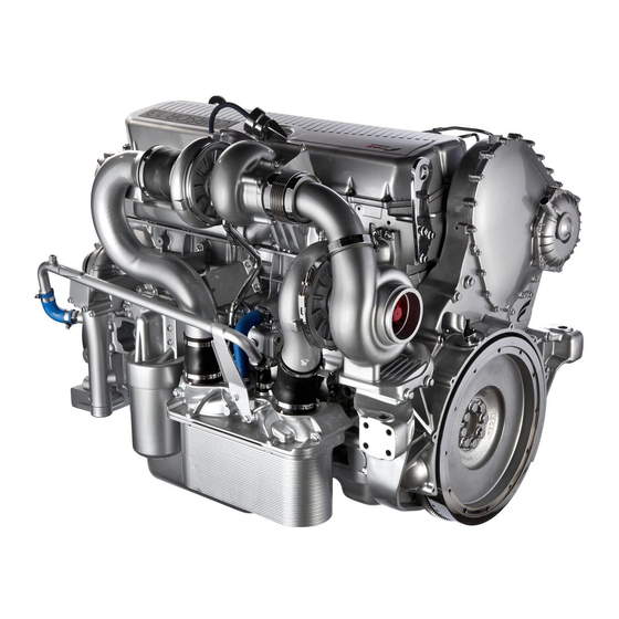
- Page 1 CURSOR 13 NON EMISSIONS CERTIFIED Power generation CR13 TE 7W F3HFA615A*D001 CR13 TE 6W F3HFA615B*D001 Technical repair manual...
- Page 2 Each intervention on the vehicle that is finalised to a modifica- tion, alteration or anything else which has not been authorised by FPT relieves FPT of any liability, and, in particular, where the assembly is covered by a warranty, each intervention will immediately invalidate the warranty.
- Page 3 CURSOR SERIES Introduction Section GENERAL INFORMATION ....SYMBOLS ......
- Page 4 CURSOR SERIES Base - 03/2015 Print P4D32C006 E...
- Page 5 CURSOR SERIES GENERAL INFORMATION Manuals for repairs are split into Parts and Sections, each one of which is marked by a number; the contents of these sections are indicated in the general table of contents. Sections with mechanical contents include technical data, tightening torque collections, tool lists, assembly connections - disconnec- tions, overhauls at the bench, troubleshooting and scheduled maintenance.
- Page 6 CURSOR SERIES Removal Intake Disconnect Refitting Exhaust Connect Disassembly Operation Dismantling Assembly ρ Compression ratio Assemble Tolerance Tighten to the specified torque Weight difference Tighten to the specified torque + angle value Rolling torque α Press or caulk Rotation Registration...
- Page 7 CURSOR SERIES GENERAL WARNINGS The warnings shown may not be representative of all the dangerous situations that may occur. Therefore, supervisors should be contacted whenever a dangerous situation that has not been described occurs. Use both specific and general-purpose toolings according to the prescriptions contained in respective use and mainte- nance handbooks.
- Page 8 Before pressure washing mechanical parts, protect electrical connectors and any control units. The tightening of screws and nuts should always be carried out according to directions. FPT’s sales and assistance net- work is available to provide any clarifications necessary to carry out any repair work not covered by this document.
- Page 9 Make sure that the wirings of electronic devices (length, type of cable, location, strapping, connection of screen braiding, grounding, etc.) conform with the FPT system and that they are carefully restored after repair or maintenance work. Measurements on the ECUs, jack connections and electrical connections of components must be done only on regular test lines, with special jacks and jack bushings.
- Page 10 CURSOR SERIES Grounding and screening The negative conductors connected to circuit ground point must be as short as possible and connected in ”star” form, ensuring that their tightening is done neatly and sufficiently (Figure 1 ref. M). The following precautions must be observed regarding the electronic components: —...
- Page 11 CURSOR SERIES CONVERSIONS BETWEEN MAIN UNITS MEASUREMENT INTERNATIONAL SYSTEM AND THE MOST COMMONLY USED DERIVED SIZES Power 1 kW = 1.36 HP 1 kW = 1.34 hp 1 HP = 0.735 kW 1 HP = 0.986 hp 1 hp = 0.746 kW...
- Page 12 CURSOR SERIES PAGE HEADER AND FOOTER INTERPRETATION Type Section Page of engine title number Basic edition referring to Number of Language When present, a closing phase of drafting printed copies of Publication month-year update month-year (Revi) to the basic edition...
- Page 13 CURSOR SERIES CURSOR SERIES STAGE IV CURSOR SERIES TIER 4B Section General information Operating diagrams Electricl equipment Scheduled Maintenance Removal - Refitting of the main engine components General mechanical overhaul Technical specifications Tools Appendix Standard safety precautions Print P4D32C006 E...
- Page 14 CURSOR SERIES Base - 03/2015 Print P4D32C006 E...
- Page 15 CURSOR SERIES UPDATE DATA Section Section name Description of modification Page Revision date Print P4D32C006 E Base - 03/2015...
- Page 16 CURSOR SERIES Base - 03/2015 Print P4D32C006 E...
- Page 17 CURSOR SERIES SECTION 1 - GENERAL INFORMATION SECTION 1 General information Page IDENTIFICATION DATA ....CORRESPONDENCE BETWEEN TECHNICAL CODES AND COMMERCIAL CODES ..
- Page 18 SECTION 1 - GENERAL INFORMATION CURSOR SERIES Base - 03/2015 Print P4D32C006 E...
- Page 19 Figure 1 225053 A. Serial number - B. Month and year construction date - C. Engine type - D. Engine family name - E. FPT Engine P/N 1. Bar code (The Bar code contains: Serial number, Manufacturing date, FPT Engine P/N)
- Page 20 SECTION 1 - GENERAL INFORMATION CURSOR SERIES CORRESPONDENCE BETWEEN TECHNICAL CODES AND COMMERCIAL CODES Technical codes Commercial Codes F3HFA615A*D001 CR13 TE 7W F3HFA615B*D001 CR13 TE 6W Base - 03/2015 Print P4D32C006 E...
- Page 21 CURSOR SERIES SECTION 1 - GENERAL INFORMATION PRODUCT TECHNICAL CODE The technical code is assigned during production; it is used to identify the main characteristics, characterise the application and the corresponding level of power output. It is stamped on one side of the crankcase near the oil filter.
- Page 22 SECTION 1 - GENERAL INFORMATION CURSOR SERIES PRODUCT COMMERCIAL CODE The commercial name has the aim of making the information on the engine characteristics more easily identifiable, bringing together engines of different families, origin and applications for which they are to be used.
- Page 23 CURSOR SERIES SECTION 1 - GENERAL INFORMATION ENGINE VIEWS Figure 3 227835 LEFT SIDE VIEW 1. Pipe for intake of external air to turbocharger - 2. Turbocharger oil outlet pipe - 3 . Refitting water inlet pipe to crankcase - 5. Radiator support bracket - 6. Radiator grille - 7. Radiator - 8. Hot compressed air pipe from turbocharger to radiator - 9.
- Page 24 SECTION 1 - GENERAL INFORMATION CURSOR SERIES Figure 5 227837 FRONT VIEW 1. Engine cold air inlet pipe - 2. Electric fan - 3. Water outlet pipe from head - 4. Hot compressed air pipe from turbocharger to radiator - 5. Turbocharger - 6. Pipe for intake of external air to turbocharger - 7.
- Page 25 CURSOR SERIES SECTION 1 - GENERAL INFORMATION Figure 7 227833 TOP VIEW 1. Radiator grille - 2. Radiator anchor - 3. Intake manifold - 4. Lubricant oil filling plug - 5. Fuel pump - 6. Blow-By cover - 7. Air filter - 8. Pipe for intake of external air to turbocharger - 9.
- Page 26 SECTION 1 - GENERAL INFORMATION CURSOR SERIES ENGINE CHARACTERISTICS F3HFA615A*D001 F3HFA615B*D001 Type Cycle Diesel 4-stroke Turbocharged Supply Injection Direct Number of cylinders 6 in line Bore Stroke Total capacity 12882 ρ Compression 16.5: 1 ratio Maximum power prime engine...
- Page 27 (2) Only use lubricants which comply with the international specifications 15W-40 ACEA E7 / API CI-4; 5W-30ACEA E4 (with fuel economy advantages). FPT recommends using original lubricant oil Urania LD 7 15W-40 / Urania FE 5W-30. (3) The amount indicated refers to torque without filter in standard conditions.
- Page 28 SECTION 1 - GENERAL INFORMATION CURSOR SERIES Base - 03/2015 Print P4D32C006 E...
-
Page 29: Table Of Contents
CURSOR SERIES SECTION 2 - OPERATING DIAGRAMS SECTION 2 Operating diagrams Page POWER SUPPLY ......- HP pump CPN 5 - 22/2 . - Page 30 SECTION 2 - OPERATING DIAGRAMS CURSOR SERIES Base - 03/2015 Print P4D32C006 E...
- Page 31 CURSOR SERIES SECTION 2 - OPERATING DIAGRAMS POWER SUPPLY The Common Rail fuel system has a special pump that continuously keeps fuel at high pressure, independently from the stroke and the cylinder which is to receive the injection and accumulates fuel in a common duct for all injectors.
- Page 32 SECTION 2 - OPERATING DIAGRAMS CURSOR SERIES Figure 2 210171 A High pressure - B Low pressure 1 High pressure pump - 2 Fuel filter - 3 Tank - 4 Fuel prefilter - 5 Engine control unit - 6 Electric injectors -...
-
Page 33: Hp Pump Cpn 5 - 22/2
CURSOR SERIES SECTION 2 - OPERATING DIAGRAMS HP pump CPN 5 - 22/2 It is a pump, equipped with two plungers, that takes drive from the distribution gear. The gear supply pump is installed on the same control shaft. Figure 3... -
Page 34: Hydraulic Accumulator (Rail)
SECTION 2 - OPERATING DIAGRAMS CURSOR SERIES Figure 4 180253 1 Plunger (2x) - 2 CP5 gear plungers - 3 Flow regulator Hydraulic accumulator (rail) Figure 5 180254 1 Pressure sensor - 2 Rail - 3 Pipes to injectors - 4 Fuel return - 5 Overpressure valve - 6 Fuel inlets from high pressure pump The rail volume is of reduced sizes to allow a quick pressurisation at startup, at idle and in case of high flow-rates. -
Page 35: Electro-Injector Crin
CURSOR SERIES SECTION 2 - OPERATING DIAGRAMS Electro-injector CRIN 3-22 Figure 6 180255 1 Electrical connection - 2 Coil - 3 High pressure fuel intake fitting - 4 Injector closing force - 5 Spray nozzle - 6 Injector nozzle - 7 Fuel return hole - 8 IQA codes - 9 Production code The electro-injectors are mounted on the cylinder head and operated by the engine control unit. - Page 36 SECTION 2 - OPERATING DIAGRAMS CURSOR SERIES Figure 7 190508 1 Coil - 2 High pressure fuel intake fitting - 3 Filter - 4 Pressure rod - 5 Needle - 6 Nozzle - 7 Pressure chamber - 8 Fuel return - 9 Control volume - 10 Pilot valve shutter The electro-injector may be considered as mainly made up of two parts: - actuator/spray nozzle consisting of pressure rod (4), needle (5) and nozzle (6).
-
Page 37: Pressure Limiter Valve
CURSOR SERIES SECTION 2 - OPERATING DIAGRAMS Pressure limiter valve Figure 8 158450 It is a safety valve mounted on the hydraulic accumulator which prevents the pressure of the fuel in the rail from exceeding the threshold 2400 bar. It consists of a shutter and a spring, calibrated so that when the pressure in the rail reaches too high a value, the valve regulates it by releasing part of the fuel to the tank. -
Page 38: Oil Filter Tightening Torques
SECTION 2 - OPERATING DIAGRAMS CURSOR SERIES Oil filter tightening torques TORQUE PART Fitting for bleeding 17.5 ± 2.5 1.75 ± 0.25 Fuel filter 32.5 ± 2.5 3.25 ± 0.25 Fuel filter support 24.5 ± 2.5 2.45 ± 0.25 Drain valve 1.5 ±... -
Page 39: Lubrication
CURSOR SERIES SECTION 2 - OPERATING DIAGRAMS LUBRICATION The engine is lubricated by gear pump driven via gears by the crankshaft. A heat exchanger regulates the temperature of the lubricating oil. It houses the oil filter, indicator sensors and safety valves. -
Page 40: Oil Pump
SECTION 2 - OPERATING DIAGRAMS CURSOR SERIES overpressure valve Oil pump Figure 12 Figure 11 60560 The oil pump (1) shall not be overhauled. If you find any da- mage, replace the entire oil pump. 73540 To change the gearing (2) of the crankshaft, see the relevant MAIN DATA TO CHECK THE SAFETY section. -
Page 41: Oil Pressure Regulator Valve
CURSOR SERIES SECTION 2 - OPERATING DIAGRAMS Oil pressure regulator valve Figure 15 Figure 14 161269 161256 A: Opening Start - B: Opening End The oil pressure relief valve is located on the left-hand side of the crankcase. MAIN DATA TO CHECK THE PRESSURE RELIEF VALVE SPRING Start of opening pressure 5 bar. -
Page 42: Filter By-Pass Valve
SECTION 2 - OPERATING DIAGRAMS CURSOR SERIES Filter by-pass valve Figure 17 73545 The valve quickly opens at a pressure of: 3.4 ± 0.3 bar. Engine oil filter Figure 18 180257 1 Oil filter support - 2 Cap O-Ring - 3 Cartridge O-Ring - 4 Filter element- 5 Closing cap - 6 Drain plug... -
Page 43: Valve Integrated In Piston Cooling Nozzle
CURSOR SERIES SECTION 2 - OPERATING DIAGRAMS tightening torque Oil filter retainer at the support base 60 ±5 Nm Drain plug on the engine oil filter 6.5 ±1.5 Nm Valve integrated in piston cooling nozzle The valve allows oil to enter and thus lubrication of pistons only above the pressure value shown below. -
Page 44: Oil Vapour Recirculation (Blow-By)
SECTION 2 - OPERATING DIAGRAMS CURSOR SERIES Oil vapour recirculation (Blow-by) Part of the gas produced by combustion leaks out of the piston gaskets through the openings of the piston rings, into the sump and mixes with the oil vapour it contains. -
Page 45: Cooling
CURSOR SERIES SECTION 2 - OPERATING DIAGRAMS COOLING Figure 21 227831 COOLING SYSTEM DIAGRAM A. Water coming into pump - B. Water circulating in the engine - C. Water leaving the thermostat 1. Water/oil heat exchanger - 2. Refitting water inlet pipe to pump - 3. Water pump - 4. Clean the heat exchanger with aftercooler (radiator) - 5. -
Page 46: Operation
SECTION 2 - OPERATING DIAGRAMS CURSOR SERIES operation Thermostat The water pump driven by a poly-V belt by the crankshaft Water circulating in the engine sends coolant into the crankcase and with a greater head into the cylinder head. Figure 23... -
Page 47: Description
CURSOR SERIES SECTION 2 - OPERATING DIAGRAMS TURBOCHARGING Figure 25 227830 TURBOCHARGING DIAGRAM A. Cold compressed air - B. Intake air - C. Compressed air (hot) - D. Exhaust gas 1. Clean the heat exchanger with aftercooler (radiator) - 2. Intake manifold - 3. Air filter - 4. turbocharger... -
Page 48: Turbocharger
SECTION 2 - OPERATING DIAGRAMS CURSOR SERIES turbocharger Figure 26 75532 A. CLOSED THROTTLE VALVE B. THROTTLE VALVE OPEN Figure 27 A. Lubricant oil - B. Uncompressed air - C. Compressed air - D. Exhaust gas 1. Exhaust gas intake from manifold - 2. Exhaust gas outlet (to outside) - 3. Oil outlet - 4. Air inlet - 5. Oil inlet - 6. -
Page 49: Air Filter
CURSOR SERIES SECTION 2 - OPERATING DIAGRAMS Air filter Figure 28 227829 1. Filter element seat - 2. Condensation exhaust valve - 3. External air intake By means of the aspiration created by the engine, the outside air flows through the air socket (3) and the centrifugal move- ment is imparted at high speed by the wings aimed at the filter. - Page 50 SECTION 2 - OPERATING DIAGRAMS CURSOR SERIES Base - 03/2015 Print P4D32C006 E...
- Page 51 CURSOR SERIES SECTION 3 - ELECTRIC EQUIPMENT SECTION 3 Electrical equipment Page MAIN COMPONENTS ....ENGINE SIDE WIRING ....
- Page 52 SECTION 3 - ELECTRIC EQUIPMENT CURSOR SERIES Base - 03/2015 Print P4D32C006 E...
- Page 53 CURSOR SERIES SECTION 3 - ELECTRIC EQUIPMENT MAIN COMPONENTS Figure 1 227828 1. Air heater resistor - 2. Alternator - 3. Air temperature and pressure sensor - 4. Engine management control unit - 5. Fuel high pressure and temperature sensor - 6. Fuel filter with pressure and temperature sensor - 7.
-
Page 54: Engine Side Wiring
SECTION 3 - ELECTRIC EQUIPMENT CURSOR SERIES ENGINE SIDE WIRING Engine side wiring diagram Figure 2 224074 Base - 03/2015 Print P4D32C006 E... -
Page 55: Engine Side Wiring Diagram
CURSOR SERIES SECTION 3 - ELECTRIC EQUIPMENT Engine side wiring diagram (Topographic view) Figure 3 225059 1. Oil high pressure and temperature sensor - 2. Rpm sensor - 3. Fuel filter clogged sensor - 4. Fuel temperature sensor - 5. EDC connector (96-way) - 6. Fuel pre-filter clogged sensor - 7. Turbocharging air pressure and temperature sensor - 8. -
Page 56: Pin Out Connector 1A (96 Pin) - Control Unit Edc 17 Hp 41
SECTION 3 - ELECTRIC EQUIPMENT CURSOR SERIES PIN OUT CONNECTOR 1A (96 PIN) - CONTROL UNIT EDC 17 HP 41 Figure 4 190542 Signal Cylinder 1 injector Cylinder 6 injector Cylinder 5 injector Oil pressure and temperature sensor ground Air pressure temperature sensor supply... - Page 57 CURSOR SERIES SECTION 3 - ELECTRIC EQUIPMENT Signal Air pressure temperature sensor signal Coolant temperature sensor signal Crankshaft pressure sensor ground Cylinder 1 injector Cylinder 2 injector Cylinder 3 injector ZME Fuel metering unit power supply Common ground (fuel temperature sensor, coolant temperature sensor)
- Page 58 SECTION 3 - ELECTRIC EQUIPMENT CURSOR SERIES Signal Air pressure temperature sensor signal Air temperature and pressure sensor ground Base - 03/2015 Print P4D32C006 E...
-
Page 59: Crin Injector 3.3
CURSOR SERIES SECTION 3 - ELECTRIC EQUIPMENT CRIN INJECTOR 3.3 Rail pressure sensor (RSD 4) Figure 5 Figure 6 178241 1. Electrical connections - 2. Electromagnet assembly This is an N.O. solenoid valve. They are connected to the EDC ECU on connector 2. -
Page 60: Pressure Sensor Inside Engine Crankcase
SECTION 3 - ELECTRIC EQUIPMENT CURSOR SERIES Pressure sensor inside engine crankcase The crankshaft pressure sensor is used to measure the pres- sure inside the engine. Figure 7 190512 Description ECU pin Power supply EDC17, pin A/32 Ground EDC17, pin A/42... -
Page 61: Crankshaft Sensor
CURSOR SERIES SECTION 3 - ELECTRIC EQUIPMENT Crankshaft sensor Figure 9 This sensor is an inductive one and is located on the flywheel. NOTE If this signal fails the rev counter will not work. WARNING The sensor gap is not adjustable. -
Page 62: Camshaft Sensor
SECTION 3 - ELECTRIC EQUIPMENT CURSOR SERIES Camshaft sensor Figure 12 This inductive sensor is located on the camshaft. The signal generated by this sensor is used by the EDC17 control unit as the injection timing signal. WARNING The sensor gap is not adjustable. -
Page 63: Fuel Temperature Sensor
CURSOR SERIES SECTION 3 - ELECTRIC EQUIPMENT Fuel temperature sensor Coolant temperature sensor It is an N.T.C type sensor and is located on the fuel filter. It is an N.T.C type sensor and is located on the fuel filter. It detects the fuel temperature thus enabling the electronic... -
Page 64: Oil Pressure And Temperature Sensor
SECTION 3 - ELECTRIC EQUIPMENT CURSOR SERIES Oil pressure and temperature sensor Turbocharging air pressure and temperature sensor It is mounted on the crankcase. This is fitted on the intake manifold; the sensor described ser- The signals measured are transmitted to the EDC17 control... -
Page 65: Fuel Filter Clogged Sensor
CURSOR SERIES SECTION 3 - ELECTRIC EQUIPMENT Fuel filter clogged sensor It is a normally closed electric sensor which identifies the clogged fuel filter by calculating the pressure between its two doors. Figure 22 190523 Description ECU pin Ground (-) -
Page 66: Alternator
SECTION 3 - ELECTRIC EQUIPMENT CURSOR SERIES < ALTERNATOR Figure 24 106283 B+: Positive +30V - B-: Negative - S: battery voltage sensor - IG: alternator activation - L: to recharging indicator Specifications Supplier MITSUBISHI Rated voltage 24 V Nominal supply current... - Page 67 CURSOR SERIES SECTION 3 - ELECTRIC EQUIPMENT < ELECTRIC STARTER MOTOR Figure 27 221067 Voltage 24 V Nominal power 7.8 KW (SAE J544B 24V Heavy Duty) Rotation direction control side clockwise Pinion number of teeth Supplier DENSO Weight ~ 10.5 kg Tightening torque on terminal 30 26 ±...
- Page 68 SECTION 3 - ELECTRIC EQUIPMENT CURSOR SERIES Electric starter motor wiring diagrams Figure 28 221066 Electric starter motor characteristics Ref. Description Measurement unit Torque Current strength Power Voltage Speed Base - 03/2015 Print P4D32C006 E...
- Page 69 CURSOR SERIES SECTION 3 - ELECTRIC EQUIPMENT < Figure 29 Electric starter motor characteristics 215787 WIRING DIAGRAM 1. Main current contactor - 2. Control solenoid - 3. Electric engine - 4. Battery/ies Print P4D32C006 E Base - 03/2015...
- Page 70 SECTION 3 - ELECTRIC EQUIPMENT CURSOR SERIES < Base - 03/2015 Print P4D32C006 E...
- Page 71 CURSOR SERIES SECTION 4 - SCHEDULED MAINTENANCE SECTION 4 Scheduled maintenance Page SCHEDULED MAINTENANCE ... . . - Introduction ......
- Page 72 SECTION 4 - SCHEDULED MAINTENANCE CURSOR SERIES Base - 03/2015 Print P4D32C006 E...
-
Page 73: Scheduled Maintenance
CURSOR SERIES SECTION 4 - SCHEDULED MAINTENANCE SCHEDULED MAINTENANCE Introduction To ensure best operating conditions, on the following pages are indicated the checks, tests and adjustments which shall be carried out on the different parts at the established time. The frequencies of the maintenance operations are indicative since the engine use and its characteristics are essential to evaluate replacements and checks. - Page 74 SECTION 4 - SCHEDULED MAINTENANCE CURSOR SERIES NOTE The scheduled maintenance operations are only valid if the fitter observes all installation regulations provided by FPT. Furthermore, the fitted appliances must always be in compliance with the torque, power and engine speed for which the engine was designed.
-
Page 75: How To Proceed
CURSOR SERIES SECTION 4 - SCHEDULED MAINTENANCE CHECKS TO BE MADE DURING PERIODS Engine coolant level check (example) OF USE HOW TO PROCEED Only proceed when the engine is not turning and is at low temperature in order not to run the risk of burns. -
Page 76: Engine Visual Inspection
SECTION 4 - SCHEDULED MAINTENANCE CURSOR SERIES Engine visual inspection Inspection cleaning of the air filter and relative seat Perform a thorough check before start-up in order to obtain maximum engine duration. Figure 2 Check for any leaks (oil, coolant and fuel), broken or weake- ned pipes, loose clips and bolts, worn belt, wiring (loose con- nections, worn or frayed cables) and a build-up of dirt;... -
Page 77: Check Tension And Condition Of Ancillary Belt
CURSOR SERIES SECTION 4 - SCHEDULED MAINTENANCE Check tension and condition of ancillary belt PERIODIC MAINTENANCE - HOW TO PROCEED Figure 3 Draining the water from the fuel prefilter (if any) Figure 4 227778 Only proceed when the engine is not turning and is at low temperature so as not to run the risk of burns. -
Page 78: Change Engine Lubricant Oil
SECTION 4 - SCHEDULED MAINTENANCE CURSOR SERIES Proceed with the refilling operation through the hole (2) si- Change engine lubricant oil tuated on the tappet cover, using lubricant oil that complies with the international standards as indicated in Section 1 - Figure 5 General table ”General Characteristics”. -
Page 79: Change Lubricant Oil Filter
CURSOR SERIES SECTION 4 - SCHEDULED MAINTENANCE Change lubricant oil filter After changing the engine lubricant oil make sure Figure 7 that the level does not exceed the ”Max” limit on the oil level dipstick. Make sure that the dipstick is fully inserted and that the filler plug is tightened fully in the clockwise direction. -
Page 80: Replace Fuel Prefilter (If Fitted) (Example)
SECTION 4 - SCHEDULED MAINTENANCE CURSOR SERIES Replace fuel prefilter Figure 9 (if fitted) (example) Figure 8 221041 - Loosen the following bleed connectors connecting them to the designated pipes to allow the residue to flow into 221044 suitable containers and prevent any soiling: ... -
Page 81: Replacing Fuel Filter
CURSOR SERIES SECTION 4 - SCHEDULED MAINTENANCE Replacing fuel filter Figure 11 Figure 10 221041 - Loosen the following bleed connectors connecting them 227782 to the designated pipes to allow the residue to flow into Only proceed when the engine is not turning and is at low suitable containers and prevent any soiling: temperature so as not to run the risk of burns. -
Page 82: Change Air Filter
SECTION 4 - SCHEDULED MAINTENANCE CURSOR SERIES Change air filter Replacing blow-by filter element See the instructions in the section AIR FILTER INSPECTION Figure 13 AND CLEANING. Replace auxiliary member drive belt Figure 12 227783 - Unscrew the screws (3) and remove the cover (4). -
Page 83: Unscheduled Maintenance
CURSOR SERIES SECTION 4 - SCHEDULED MAINTENANCE UNSCHEDULED MAINTENANCE Check the tappet clearances and adjusting if - HOW TO PROCEED necessary Figure 15 Visual turbocharger inspection Only proceed when the engine is not turning over. Visually check that the turbine, impellers of the compresser and the relative intake/outlet pipes are not obstructed or da- maged. -
Page 84: Replace Engine Coolant
SECTION 4 - SCHEDULED MAINTENANCE CURSOR SERIES Replace engine coolant Failure to observe the procedure described above Figure 16 does not guarantee the presence of the correct quantity of coolant in the engine. When the engine is hot, pressure builds up in the cooling circuits which may eject hot liquid violen- tly, resulting in a risk of burns. - Page 85 CURSOR SERIES SECTION 5 - REMOVAL - REFITTING OF THE MAIN ENGINE COMPONENTS SECTION 5 Removal-refitting of the main engine components Page PROTECTIVE GRILLE REMOVAL - REFITTING - Removal ......
- Page 86 SECTION 5 - REMOVAL - REFITTING OF THE MAIN ENGINE COMPONENTS CURSOR SERIES Page Page BLOW-BY REMOVAL-REFITTING ... - Removal ......
-
Page 87: Protective Grille Removal - Refitting
CURSOR SERIES SECTION 5 - REMOVAL - REFITTING OF THE MAIN ENGINE COMPONENTS PROTECTIVE GRILLE RADIATOR ASSEMBLY REMOVAL - REFITTING REMOVAL - REFITTING Remove the protection grilles as described in the procedure Removal ”PROTECTION GRILL REMOVAL - REFITTING”. Figure 1... -
Page 88: Refitting
SECTION 5 - REMOVAL - REFITTING OF THE MAIN ENGINE COMPONENTS CURSOR SERIES Refitting Figure 4 Figure 5 227754 Slacken the clamp (1) and from the radiator assembly (3) 227754 disconnect the compressed air supply pipe to the aftercooler. Undo the fastening screws of the tie road (2) of the radiator... -
Page 89: Fan Removal - Refitting
CURSOR SERIES SECTION 5 - REMOVAL - REFITTING OF THE MAIN ENGINE COMPONENTS FAN REMOVAL - REFITTING Figure 6 Remove the protection grilles as described in the procedure ”PROTECTION GRILL REMOVAL - REFITTING”. Remove the radiator assembly as described in the procedure ”RADIATOR ASSEMBLY REMOVAL - REFITTING”. -
Page 90: Refitting
SECTION 5 - REMOVAL - REFITTING OF THE MAIN ENGINE COMPONENTS CURSOR SERIES Refitting REMOVAL-REFITTING MAIN ENGINE COMPONENTS Figure 8 ENGINE CABLE REMOVAL-REFITTING Removal Figure 9 227755 Fit the fan (2) together with the spacer (3) onto the pulley and tighten the screws (1) to the torque indicated in the table. -
Page 91: Removal-Refitting Of Ancillary Belt
CURSOR SERIES SECTION 5 - REMOVAL - REFITTING OF THE MAIN ENGINE COMPONENTS Refitting REMOVAL-REFITTING ANCILLARY BELT Figure 11 Removal Remove the protection grilles as described in the procedure ”PROTECTION GRILL REMOVAL - REFITTING”. Remove the radiator assembly as described in the procedure ”RADIATOR ASSEMBLY REMOVAL - REFITTING”. -
Page 92: Removal
SECTION 5 - REMOVAL - REFITTING OF THE MAIN ENGINE COMPONENTS CURSOR SERIES ALTERNATOR REMOVAL-REFITTING Figure 15 Removal Figure 13 221083 Unscrew the screws (1, 2) and remove the alternator (3). 227756 Ref. Description M8 x 1.25 screws Undo the top screws (1), side screws (2) on intake side and bottom screws (3) and remove the grilles (4) and () that M10 x 1.5 screws... - Page 93 CURSOR SERIES SECTION 5 - REMOVAL - REFITTING OF THE MAIN ENGINE COMPONENTS Figure 17 227757 With the help of a 1/2 square-head wrench, act on the belt tensioner (2) and fit the ancillary belt (1) on the alternator pulley.
- Page 94 SECTION 5 - REMOVAL - REFITTING OF THE MAIN ENGINE COMPONENTS CURSOR SERIES WATER PUMP REMOVAL-REFITTING Figure 19 Removal Remove the protection grilles as described in the procedure ”PROTECTION GRILL REMOVAL - REFITTING”. Remove the radiator assembly as described in the procedure ”RADIATOR ASSEMBLY REMOVAL - REFITTING”.
- Page 95 CURSOR SERIES SECTION 5 - REMOVAL - REFITTING OF THE MAIN ENGINE COMPONENTS Refitting Figure 23 Figure 22 225040 Using a 1/2 inch square wrench, operate on the belt tensioner 224087 (1) and position the control belt of the crankshaft /...
- Page 96 SECTION 5 - REMOVAL - REFITTING OF THE MAIN ENGINE COMPONENTS CURSOR SERIES Figure 27 ELECTROMAGNETIC COUPLING PULLEY REMOVAL-REFITTING Removal Remove the protection grilles as described in the procedure ”PROTECTION GRILL REMOVAL - REFITTING”. Remove the radiator assembly as described in the procedure ”RADIATOR ASSEMBLY REMOVAL - REFITTING”.
- Page 97 CURSOR SERIES SECTION 5 - REMOVAL - REFITTING OF THE MAIN ENGINE COMPONENTS Figure 29 Figure 30 225046 225040 Fit the pulley electromagnetic coupling assembly (2) and Using a 1/2 inch square wrench, operate on the belt tensioner tighten the screws (1) to the torque indicated in the table.
- Page 98 SECTION 5 - REMOVAL - REFITTING OF THE MAIN ENGINE COMPONENTS CURSOR SERIES Refitting THERMOSTAT CASE REMOVAL-REFITTING Figure 34 Removal Figure 32 227758 Assemble the thermostat, the thermostat box (3), with relative gaskets and tighten screws (1, 2) to the torque shown 227753 in the table.
-
Page 99: Starter Motor Removal-Refitting
CURSOR SERIES SECTION 5 - REMOVAL - REFITTING OF THE MAIN ENGINE COMPONENTS STARTER MOTOR REMOVAL-REFITTING Figure 36 Removal Figure 37 227753 Laterally install the fan protection grilles (4) and (5). Tighten and lock the top screws (1) the bottom screw (3) and 227759 side screws (2) to the torque in the table. -
Page 100: Removal
SECTION 5 - REMOVAL - REFITTING OF THE MAIN ENGINE COMPONENTS CURSOR SERIES Figure 41 TURBOCHARGER REMOVAL-REFITTING Removal Figure 39 225025 Unscrew the nuts (1) extract the pins and remove the turbocharger (2) from the exhaust manifold along with its gasket. - Page 101 CURSOR SERIES SECTION 5 - REMOVAL - REFITTING OF THE MAIN ENGINE COMPONENTS Figure 43 Figure 45 225062 227760 Tighten the screws securing the turbocharger following the Connect the sleeve (3) of the combustion air intake pipe to sequence indicated in the figure.
-
Page 102: Exhaust Manifold Removal-Refitting
SECTION 5 - REMOVAL - REFITTING OF THE MAIN ENGINE COMPONENTS CURSOR SERIES EXHAUST MANIFOLD Figure 48 REMOVAL-REFITTING Removal Figure 46 227762 Unscrew the fastening screws (1) and remove the exhaust manifold (2) together with the turbocharger (3) and the gaskets. - Page 103 CURSOR SERIES SECTION 5 - REMOVAL - REFITTING OF THE MAIN ENGINE COMPONENTS Figure 50 Figure 52 225030 Tighten the fastening screws following the sequence indicated in the figure. NOTE Lubricate the screws with graphite oil. 227760 Connect the sleeve (3) of the combustion air intake pipe to Figure 51 the turbocharger and tighten the clamps.
-
Page 104: Oil Filter And Mount Removal-Refitting
SECTION 5 - REMOVAL - REFITTING OF THE MAIN ENGINE COMPONENTS CURSOR SERIES Refitting OIL FILTER AND MOUNT REMOVAL-REFITTING Figure 55 Removal Figure 53 227786 Fit the engine oil filter mount (2) together with the new gasket and tighten the screws (1) to the torque indicated in 227763 the table. -
Page 105: Heat Exchanger Removal-Refitting
CURSOR SERIES SECTION 5 - REMOVAL - REFITTING OF THE MAIN ENGINE COMPONENTS Figure 59 HEAT EXCHANGER REMOVAL-REFITTING Removal Figure 57 227764 Undo the screws (1, 5) and remove the oil return pipe from the turbocharger (2) with its gaskets. -
Page 106: Refitting
SECTION 5 - REMOVAL - REFITTING OF THE MAIN ENGINE COMPONENTS CURSOR SERIES Refitting Figure 62 Figure 60 227786 Fit the engine oil filter mount (2) together with the new gasket 227764 and tighten the screws (1) to the torque indicated in the table. -
Page 107: Removal
CURSOR SERIES SECTION 5 - REMOVAL - REFITTING OF THE MAIN ENGINE COMPONENTS Refitting OIL SUMP REMOVAL-REFITTING Removal Figure 65 NOTE Position a suitable container below the sump to collect the oil as it drains out of the drain plug. -
Page 108: Fuel Filter Removal-Refitting
SECTION 5 - REMOVAL - REFITTING OF THE MAIN ENGINE COMPONENTS CURSOR SERIES Refitting FUEL FILTER REMOVAL-REFITTING Figure 68 Removal Figure 67 227766 Replace the filtering element (3) and the O-ring seal (2) inside the bell housing support (5). 227766 Grease the O-ring seal (2) of the filter. -
Page 109: Engine Control Unit Removal-Refitting
CURSOR SERIES SECTION 5 - REMOVAL - REFITTING OF THE MAIN ENGINE COMPONENTS Refitting ENGINE CONTROL UNIT REMOVAL-REFITTING Figure 70 Removal Disconnect the engine cable connector by disconnecting it from the control unit as described in the relevant section. Figure 69... -
Page 110: Air Filter Removal - Refitting
SECTION 5 - REMOVAL - REFITTING OF THE MAIN ENGINE COMPONENTS CURSOR SERIES Refitting AIR FILTER REMOVAL - REFITTING Removal Figure 72 Figure 71 227768 Mount the bracket (7) and tighten the screws (8) to the torque 227768 in the table. -
Page 111: Blow-By Removal-Refitting
CURSOR SERIES SECTION 5 - REMOVAL - REFITTING OF THE MAIN ENGINE COMPONENTS Refitting BLOW-BY REMOVAL-REFITTING Remove the air filter as described in the procedure ”AIR FILTER REMOVAL - REFITTING”. NOTE Carefully clean the seating of the filter and the cover. -
Page 112: Intake Manifold Removal-Refitting
SECTION 5 - REMOVAL - REFITTING OF THE MAIN ENGINE COMPONENTS CURSOR SERIES Refitting INTAKE MANIFOLD REMOVAL-REFITTING Removal Figure 77 Figure 76 227769 Fit the intake manifold (2) together with the engine preheating 227769 resistor (3) and its gasket and tighten screws (1) to the torque shown in the table. -
Page 113: Fuel Pump Removal-Refitting
CURSOR SERIES SECTION 5 - REMOVAL - REFITTING OF THE MAIN ENGINE COMPONENTS Figure 80 FUEL PUMP REMOVAL-REFITTING Remove the air filter as described in the procedure “AIR FILTER REMOVAL - REFITTING”. Removal Figure 79 225032 Lock the engine flywheel in place using tool 99360351 (1) so it does not spin. - Page 114 SECTION 5 - REMOVAL - REFITTING OF THE MAIN ENGINE COMPONENTS CURSOR SERIES Figure 81 Figure 82 227770 Disconnect the electrical connection from the fuel flow regulator. Unscrew the nutes (2), remove the plugs, undo the fittings (1, 3) and remove the HP fuel pipes.
-
Page 115: Refitting
CURSOR SERIES SECTION 5 - REMOVAL - REFITTING OF THE MAIN ENGINE COMPONENTS Refitting Figure 86 Figure 84 221104 Position the bracket (3) and tighten the screws (1, 2). Position the high pressure pump (6) and tighten the screws (4, 5) to torque shown in the table. - Page 116 SECTION 5 - REMOVAL - REFITTING OF THE MAIN ENGINE COMPONENTS CURSOR SERIES Figure 87 Figure 88 225037 Fit the gear (2) and tighten the nut (1) to the torque shown in the table. 227770 Fit the HP fuel pipes, fit the plugs onto the bracket and tighten Tightening Ref.
-
Page 117: Tappet Cover Removal-Refitting
CURSOR SERIES SECTION 5 - REMOVAL - REFITTING OF THE MAIN ENGINE COMPONENTS Figure 89 TAPPET COVER REMOVAL-REFITTING Removal Figure 91 221043 Fit the new blow-by filtering element (1) into its seat and tighten the screws (2) to the torque indicated in the table. -
Page 118: Common Rail Removal-Refitting
SECTION 5 - REMOVAL - REFITTING OF THE MAIN ENGINE COMPONENTS CURSOR SERIES Figure 94 COMMON RAIL REMOVAL-REFITTING Removal Figure 93 225019 Unscrew the fittings (8) on rail and head side, screw on bracket (12) and remove the high pressure fuel supply pipes. -
Page 119: Refitting
CURSOR SERIES SECTION 5 - REMOVAL - REFITTING OF THE MAIN ENGINE COMPONENTS Refitting Tightening Ref. Description torques Figure 95 (12) Screws M6 10 ± 1 Nm Connect the fuel return pipe (7) from the rail and tighten the fittings to the torque indicated in the table. -
Page 120: Electro-Injector Removal-Refitting
SECTION 5 - REMOVAL - REFITTING OF THE MAIN ENGINE COMPONENTS CURSOR SERIES Refitting ELECTRO-INJECTOR REMOVAL-REFITTING Figure 99 Removal Figure 97 225049 Position the wiring and secure it appropriately with clamps. 227771 Connect the elctrical connections (2) to the injectors and tighten the nuts to the torque indicated in the table. -
Page 121: Rocker Arm Shaft Removal-Refitting
CURSOR SERIES SECTION 5 - REMOVAL - REFITTING OF THE MAIN ENGINE COMPONENTS Figure 103 ROCKER ARM SHAFT REMOVAL-REFITTING Removal Figure 101 224083 Use the specified tool 99360553 (1) on the rocker arm shaft (2) and remove the shaft (2) from the cylinder head. Remove the crosspieces (3) from the cylinder head. -
Page 122: Setting Rocker Free Play
SECTION 5 - REMOVAL - REFITTING OF THE MAIN ENGINE COMPONENTS CURSOR SERIES By means of a ratchet spanner, loosen the nut (1) locking the Figure 105 adjustment screw. Insert the feeler gauge blade (3) corresponding to the α operating clearance indicated in the table “Data and assembly clearance”... -
Page 123: Electro - Injectors Removal-Refitting
CURSOR SERIES SECTION 5 - REMOVAL - REFITTING OF THE MAIN ENGINE COMPONENTS Figure 110 ELECTRO - INJECTORS REMOVAL-REFITTING Removal Figure 108 224083 Use the specified tool 99360553 (1) on the rocker arm shaft (2) and remove the shaft (2) from the cylinder head. Remove the crosspieces (3) from the cylinder head. -
Page 124: Refitting
SECTION 5 - REMOVAL - REFITTING OF THE MAIN ENGINE COMPONENTS CURSOR SERIES Refitting Figure 113 Figure 115 169827 Remove the screws (1) from the brackets (2) supporting the injectors. Ref. Description Screws M8 X 1.25 X 45 Figure 114 169828 Fit the sealing gasket (2) on the injectors (1). - Page 125 CURSOR SERIES SECTION 5 - REMOVAL - REFITTING OF THE MAIN ENGINE COMPONENTS Figure 117 Figure 118 225054 Connect the high pressure fuel pipes and tighten the fittings by hand in the sequence (1, 2, 3, 6, 5, 4) to the rail and the 225045 injectors.
-
Page 126: Setting Rocker Free Play
SECTION 5 - REMOVAL - REFITTING OF THE MAIN ENGINE COMPONENTS CURSOR SERIES Setting rocker free play Figure 121 Figure 120 183457 Connect the electrical connections (1) to the injectors and 114287 block the cables using cable clamps. Take the cylinder whose clearance has to be adjusted into the combustion phase;... -
Page 127: Cylinder Head Removal-Refitting
CURSOR SERIES SECTION 5 - REMOVAL - REFITTING OF THE MAIN ENGINE COMPONENTS Figure 125 CYLINDER HEAD REMOVAL-REFITTING Remove the air filter as described in the procedure “AIR FILTER REMOVAL - REFITTING”. Removal Figure 123 227761 Loosen the screw of the bracket (1) and fitting (2) and remove the oil supply pipe to the turbocharger (3). - Page 128 SECTION 5 - REMOVAL - REFITTING OF THE MAIN ENGINE COMPONENTS CURSOR SERIES Remove the protection grilles as described in the procedure Figure 129 ”PROTECTION GRILL REMOVAL - REFITTING”. Figure 127 225017 Remove the timing sensor (1). 227758 Unscrew the screws (2) and remove the distribution cover (3).
- Page 129 CURSOR SERIES SECTION 5 - REMOVAL - REFITTING OF THE MAIN ENGINE COMPONENTS Figure 131 Figure 132 227769 Disconnect the combustion air intake pipe to the engine (4) acting on the clamp. 225050 Unscrew the screws (1) and remove the intake manifold (2) Unscrew the nutes (2), remove the plugs, undo the fittings (1, together with the engine preheating resistor (3) and its gasket.
- Page 130 SECTION 5 - REMOVAL - REFITTING OF THE MAIN ENGINE COMPONENTS CURSOR SERIES Figure 133 Figure 135 221105 221104 Unscrew the screws (2) and remove the gear (1) fitted with Unscrew the screws (1,2,4) and remove the pump support phonic wheel.
- Page 131 CURSOR SERIES SECTION 5 - REMOVAL - REFITTING OF THE MAIN ENGINE COMPONENTS Figure 137 Figure 139 221107 60500 Unscrew the screws (2) and remove the transmission gear (1). Fit puller 99340053 (2) and take off the seal (1). Ref.
- Page 132 SECTION 5 - REMOVAL - REFITTING OF THE MAIN ENGINE COMPONENTS CURSOR SERIES Figure 141 Figure 143 225019 Unscrew the fittings (8), the screw of the bracket (12) and 227745 remove the high pressure fuel supply pipes (8). Release the retainer springs of the engine brake (1).
-
Page 133: Refitting
CURSOR SERIES SECTION 5 - REMOVAL - REFITTING OF THE MAIN ENGINE COMPONENTS Figure 144 Figure 146 225061 227750 Tighten the fastening screws in the sequence shown in the Unscrew the cylinder head screws . figure. Ref. Description Screws M18 X 2 X 196... - Page 134 SECTION 5 - REMOVAL - REFITTING OF THE MAIN ENGINE COMPONENTS CURSOR SERIES Figure 148 Figure 150 α 60566 225008 Use tool 99395216 (1) for angle tightening to the torque Use a torque wrench to tighten the screws to the torque shown in the table.
- Page 135 CURSOR SERIES SECTION 5 - REMOVAL - REFITTING OF THE MAIN ENGINE COMPONENTS Figure 152 Figure 154 α 49036 60568 Tighten to angle with wrench 99395216 (1). Key the sealing gasket (1) onto the crankshaft, fit the keying device 99346260 (2) and while tightening the nut (3) drive in the sealing gasket.
- Page 136 SECTION 5 - REMOVAL - REFITTING OF THE MAIN ENGINE COMPONENTS CURSOR SERIES Figure 156 Figure 157 71774 Check that the tool for positioning the T.D.C 99360612 (1), through the seat (2) of the engine speed sensor , enters the hole (3) in the engine flywheel (4).
- Page 137 CURSOR SERIES SECTION 5 - REMOVAL - REFITTING OF THE MAIN ENGINE COMPONENTS Figure 159 Figure 161 α 221107 Fit the transmission gear (1) and tighten the screws (2) to the 225010 torque indicated in the table. Tightening sequence Tightening...
- Page 138 SECTION 5 - REMOVAL - REFITTING OF THE MAIN ENGINE COMPONENTS CURSOR SERIES Figure 162 Figure 164 α 225019 Fit the rail (10) onto the head and tighten the fastening screws 221116 (9) to the torque shown in the table.
- Page 139 CURSOR SERIES SECTION 5 - REMOVAL - REFITTING OF THE MAIN ENGINE COMPONENTS Figure 165 Figure 167 225045 Apply the tool 99360553 (1) to the rocker arm shaft (2) and 185253 mount the shaft on the cylinder head. Carefully clean the surface of the head on which the rocker Figure 166 arm cover rests.
- Page 140 SECTION 5 - REMOVAL - REFITTING OF THE MAIN ENGINE COMPONENTS CURSOR SERIES Figure 168 Figure 169 177714 185524 Using the specific tool to turn the engine flywheel 99360321, Camshaft rotation angle turn the crankshaft in the opposite direction to that of...
- Page 141 CURSOR SERIES SECTION 5 - REMOVAL - REFITTING OF THE MAIN ENGINE COMPONENTS Figure 170 NOTE While performing this operation recover the clearance between the camshaft gears. Tighten the screws (2) to the torque specified in the table. Tightening Ref.
- Page 142 SECTION 5 - REMOVAL - REFITTING OF THE MAIN ENGINE COMPONENTS CURSOR SERIES Figure 173 Figure 174 α 221120 Fit the gear (2) with the four slotted holes (1) centred in relation to the holes securing the camshaft and tighten the screws to the torque shown in the table.
- Page 143 CURSOR SERIES SECTION 5 - REMOVAL - REFITTING OF THE MAIN ENGINE COMPONENTS If the tool (2) is difficult to fit, loosen the screws (3) and direct Figure 175 the phonic wheel (1) properly so as to position the tool (2) on the tooth correctly.
- Page 144 SECTION 5 - REMOVAL - REFITTING OF THE MAIN ENGINE COMPONENTS CURSOR SERIES Figure 177 Use a suitable wrench to screw or unscrew rocker arm (2) adjusting screw. Check that the thickness gauge blade (3) can slide with a slight friction.
- Page 145 CURSOR SERIES SECTION 5 - REMOVAL - REFITTING OF THE MAIN ENGINE COMPONENTS Figure 180 Figure 181 Fit the intake manifold (2) together with the engine preheating 225050 resistor (3) and its gasket and tighten screws (1) to the torque shown in the table.
- Page 146 SECTION 5 - REMOVAL - REFITTING OF THE MAIN ENGINE COMPONENTS CURSOR SERIES Tightening Figure 183 Ref. Description torques Screws M6 X 1 X 25 7 ± 1 Nm Figure 185 225037 Fit the gear (2) and tighten the nut (1) to the torque shown in the table.
- Page 147 CURSOR SERIES SECTION 5 - REMOVAL - REFITTING OF THE MAIN ENGINE COMPONENTS Fit the engine oil return pipe from the turbocharger (5) with Figure 187 the new gaskets and tighten the screws (4, 6) to the torque indicated in the table.
- Page 148 SECTION 5 - REMOVAL - REFITTING OF THE MAIN ENGINE COMPONENTS CURSOR SERIES Base - 03/2015 Print P4D32C006 E...
- Page 149 CURSOR SERIES SECTION 6 - GENERAL MECHANICAL OVERHAUL SECTION 6 General mechanical overhaul Page ENGINE DISASSEMBLING ....- Disassembly of G-Drive components ..
- Page 150 SECTION 6 - GENERAL MECHANICAL OVERHAUL CURSOR SERIES Page Page DISASSEMBLY OF ENGINE AT BENCH - Crankshaft removal ..... (COMPONENTS AT THE TOP PART 1) .
- Page 151 CURSOR SERIES SECTION 6 - GENERAL MECHANICAL OVERHAUL Page Page - Measuring the piston pin diameter ..- Rocker shaft check ..... .
- Page 152 SECTION 6 - GENERAL MECHANICAL OVERHAUL CURSOR SERIES Page Page - High pressure pump flange assembly ..- Timing gear assembly cover mounting ..- Fitting camshaft .
-
Page 153: Engine Disassembling
CURSOR SERIES SECTION 6 - GENERAL MECHANICAL OVERHAUL Figure 2 ENGINE DISASSEMBLING Disassembly of G-Drive components Remove the protection grilles as described in the procedure ”PROTECTION GRILL REMOVAL - REFITTING” - Section 5. Remove the radiator assembly as described in the procedure ”RADIATOR ASSEMBLY REMOVAL - REFITTING”... -
Page 154: Removal Of Components Hindering Bracket Assembly
SECTION 6 - GENERAL MECHANICAL OVERHAUL CURSOR SERIES Figure 5 Removal of components hindering bracket assembly Engine cable removal Protect the electrical parts before washing wish pressurised water spray. Before securing the engine onto the rotating stand 99322230, remove the engine cable disconnecting it from the control unit and from all sensors/senders to which it is connected. - Page 155 CURSOR SERIES SECTION 6 - GENERAL MECHANICAL OVERHAUL Removal of the oil filter with relative support and Removal of the air compressor input point water inlet pipe to crankcase Figure 8 Figure 7 224057 Undo the screws (1) and remove the air compressor input point support (2).
-
Page 156: Fitting The Engine On The Rotating Stand
SECTION 6 - GENERAL MECHANICAL OVERHAUL CURSOR SERIES Fitting the engine on the rotating stand The engine oil is highly pollutant and noxious. In case of contact with skin, wash thoroughly with NOTE Position a suitable container below the sump to water and detergent. -
Page 157: Disassembly Of Engine At Bench (Components At The Front)
CURSOR SERIES SECTION 6 - GENERAL MECHANICAL OVERHAUL DISASSEMBLY OF ENGINE AT BENCH Coolant pump alternator drive belt (COMPONENTS AT THE FRONT) disassembly Damper flywheel removal Figure 13 Figure 11 166728 71702 Using a 1/2 inch square wrench (1), act in the direction of the arrow, remove the ancillary drive belt (2). -
Page 158: Electromagnetic Coupling Pulley Removal
SECTION 6 - GENERAL MECHANICAL OVERHAUL CURSOR SERIES Alternator support removal Assembly of auxiliary parts Figure 15 Figure 17 224063 225016 Unscrew the screws (1) and remove the alternator support Unscrew the screw (5) and remove the automatic belt ten- (2). -
Page 159: Crankshaft Front Gasket Removal
CURSOR SERIES SECTION 6 - GENERAL MECHANICAL OVERHAUL Crankshaft front gasket removal DISASSEMBLY OF ENGINE AT BENCH (COMPONENTS AT EXHAUST SIDE) Figure 19 Turbocharger and exhaust manifold removal Figure 20 224068 Fit puller 99340053 (2) and take off the crankshaft seal (1). Ex- tract the flange (3). -
Page 160: Heat Exchanger Removal
SECTION 6 - GENERAL MECHANICAL OVERHAUL CURSOR SERIES DISASSEMBLY OF ENGINE AT BENCH Figure 22 (COMPONENTS AT THE INTAKE SIDE PART 1) Disassembly of the starter motor Figure 24 221091 Unscrew the nuts (2, 4) and detach the turbocharger (4) from the exhaust manifold (3). -
Page 161: Engine Control Unit Removal
CURSOR SERIES SECTION 6 - GENERAL MECHANICAL OVERHAUL Engine control unit removal DISASSEMBLY OF ENGINE AT BENCH (COMPONENTS AT THE REAR SIDE PART 1) Figure 26 Blow-by case removal Figure 27 221097 Unscrew the screws (1) and remove the blow-by case (2). -
Page 162: Timing Gear Cover Removal
SECTION 6 - GENERAL MECHANICAL OVERHAUL CURSOR SERIES Timing gear cover removal DISASSEMBLY OF ENGINE AT BENCH (COMPONENTS AT THE INTAKE SIDE PART 2) Figure 29 Fuel filter removal Figure 31 225017 Remove the timing sensor (1) Unscrew the screws (2) and remove the distribution cover (3). - Page 163 CURSOR SERIES SECTION 6 - GENERAL MECHANICAL OVERHAUL Figure 33 Figure 34 221104 227747 Unscrew the screws (1,2,4) and remove the bracket (3). Unscrew the nutes (1), remove the plugs, undo the fittings, and remove the HP fuel pipes (2).
-
Page 164: Disassembly Of Engine At Bench (Components At The Rear Side Part 2)
SECTION 6 - GENERAL MECHANICAL OVERHAUL CURSOR SERIES DISASSEMBLY OF ENGINE AT BENCH Figure 38 (COMPONENTS AT THE REAR SIDE PART 2) Timing gear removal Figure 36 221107 Unscrew the screws (2) and remove the idle gear (1). Ref. Description Screws M12 X 1.75 X 110... -
Page 165: Crankshaft Rear Gasket Removal
CURSOR SERIES SECTION 6 - GENERAL MECHANICAL OVERHAUL Crankshaft rear gasket removal Flywheel case removal Figure 40 Figure 42 60500 Fit puller 99340053 (2) and take off the seal (1). Removing engine mounts Figure 41 225018 Unscrew the screws (1) and remove the flywheel case (2). -
Page 166: Connecting Rod Removal
SECTION 6 - GENERAL MECHANICAL OVERHAUL CURSOR SERIES Connecting rod removal DISASSEMBLY OF ENGINE AT BENCH (COMPONENTS AT THE TOP PART 2) Figure 44 Rocker arm shaft removal Figure 46 221112 Unscrew the screw (1) and remove the connecting rod (2). -
Page 167: Rail Removal
CURSOR SERIES SECTION 6 - GENERAL MECHANICAL OVERHAUL Rail removal Injector removal Figure 48 Figure 49 183457 Unscrew the nuts and disconnect the electrical connections 225019 (1) from the electro-injectors. Unscrew the fittings (8), the screw of the bracket (12) and remove the high pressure fuel supply pipes (8). -
Page 168: Removing The Engine Brake Cylinders
SECTION 6 - GENERAL MECHANICAL OVERHAUL CURSOR SERIES Camshaft removal Figure 51 Figure 53 60514 Mount suitable plugs inside electro-injector seats (1). Remove the camshaft (2). Cylinder head removal 169826 Figure 54 Position the tool 99342157 for extraction the injectors (1) and remove the injectors (2) from the head. -
Page 169: Disassembly Of Engine At Bench (Components At The Bottom)
CURSOR SERIES SECTION 6 - GENERAL MECHANICAL OVERHAUL DISASSEMBLY OF ENGINE AT BENCH DISASSEMBLY OF ENGINE AT BENCH (COMPONENTS AT THE BOTTOM) (CRANKCASE COMPONENTS SIDE) Oil sump removal Connecting rod removal Figure 55 Figure 57 60516 Turn the engine on the rotating stand. -
Page 170: Lower Crankcase Removal
SECTION 6 - GENERAL MECHANICAL OVERHAUL CURSOR SERIES Lower crankcase removal Main bearings and oil nipples removal Figure 59 Figure 61 60519 47571 Using an appropriate wrench and the hex wrench unscrew the Remove the main half-bearings (1). screws (1) and (2) and take off the lower crankcase. -
Page 171: Crankcase Checks
CURSOR SERIES SECTION 6 - GENERAL MECHANICAL OVERHAUL Figure 64 CRANKCASE ASSEMBLY CHECKS Crankcase checks Figure 62 60595 A = Selection class 135.000 - 135.013 70166 = Selection class 135.011 - 135.024 After disassembling the engine, thoroughly clean the cylinder-- = Marking area crankcase assembly. - Page 172 SECTION 6 - GENERAL MECHANICAL OVERHAUL CURSOR SERIES Figure 66 60598 Cylinder liners can be removed and fitted several times into different seats, if needed. Figure 67 221075 During checks, make sure that the main data for the cylinder liners is the same as in the figure.
-
Page 173: Cylinder Liners Removal
CURSOR SERIES SECTION 6 - GENERAL MECHANICAL OVERHAUL Cylinder liners Removal Figure 70 Figure 68 47577 60520A Position the extraction tool 99360706 (2) and the plate 99360728 (4), as shown in the figure, making sure that the pla- Check the protrusion of the cylinder liners using the tool te (4) rests correctly on the cylinder liner. -
Page 174: Crankshaft Measurements
SECTION 6 - GENERAL MECHANICAL OVERHAUL CURSOR SERIES Figure 72 60521 Once assembly is complete, block the cylinder liners (1) at the crankcase (2) with stud bolts 99360703 (3). Crankshaft measurements Figure 73 Main journals upper bearing shells 38.700 39.000 47.785... - Page 175 CURSOR SERIES SECTION 6 - GENERAL MECHANICAL OVERHAUL Main half-bearings thickness Figure 75 Check the condition of the crankshaft main journals; there must no be signs of scoring, ovalisation or excessive wear . The values shown refer to rated pin diameter.
-
Page 176: Measuring Crankpins
SECTION 6 - GENERAL MECHANICAL OVERHAUL CURSOR SERIES Measuring crankpins Figure 78 Figure 77 224077 47536 Y=Crankpin fitting detail Before grinding the pins, using a micrometer (1), measure the During the grinding operation, pay attention to the values of main journals of the shaft (2) and decide, on the basis of the the crankpins shown in Y. -
Page 177: Defining The Diameter Class Of The Seats For Half-Bearings On The Crankcase
CURSOR SERIES SECTION 6 - GENERAL MECHANICAL OVERHAUL Defining the diameter class of the seats for half-bearings on the crankcase Figure 80 190208 To identify the diameter class of the seats for the main half-bearings, look at the front part of the crankcase in the position as indicated in the figure. - Page 178 SECTION 6 - GENERAL MECHANICAL OVERHAUL CURSOR SERIES Defining the diameter class of the main journals and crankpins In order to identify the diameter class of the crankpins and main journals, identify the three sets of figures marked on the front of the crankshaft.
-
Page 179: Defining The Diameter Class Of The Main Journals
CURSOR SERIES SECTION 6 - GENERAL MECHANICAL OVERHAUL Defining the diameter class of the main journals (nominal diameter) In order to identify the diameter class of the main journals, identify the three sets of figures marked on the front of the crankshaft... -
Page 180: (Nominal Diameter)
SECTION 6 - GENERAL MECHANICAL OVERHAUL CURSOR SERIES Defining the diameter class of the crankpins (nominal diameter) In order to identify the diameter class of the crankpins, identify the three sets of figures marked on the front of the crankshaft. -
Page 181: Selection Of Main Half-Bearings
CURSOR SERIES SECTION 6 - GENERAL MECHANICAL OVERHAUL SELECTION OF MAIN HALF-BEARINGS Depending on the thickness of the half-bearings, the tolerance classes are selected, distinguished by a coloured mark. The tables give the specifications of the main bearings available as spare parts in the standard sizes (STD) and in the permissible oversizes (+0.127, +0.254, +0.508). - Page 182 SECTION 6 - GENERAL MECHANICAL OVERHAUL CURSOR SERIES Figure 87 210305 1. Coloured marking area +0.127 +0.254 +0.508 210311 1.960 1.970 2.087 - 2.097 2.214 - 2.224 Red/Black 2.023 - 2.033 Green 1.970 -1.980 2.097 - 2.107 2.224 - 2.234 Green\Black 2.033 - 2.043...
-
Page 183: Main Half-Bearing Selection (Nominal Diameter)
CURSOR SERIES SECTION 6 - GENERAL MECHANICAL OVERHAUL Main half-bearing selection (nominal diameter) After detecting, for each main journal, the necessary data on crankcase and crankshaft, select the type of half-bearings to be used, in compliance with the following table:. -
Page 184: Main Half-Bearings Selection (Rectified Pins)
SECTION 6 - GENERAL MECHANICAL OVERHAUL CURSOR SERIES Main half-bearings selection (rectified pins) If the journals have been rectified, the procedure described cannot be applied. In this case, make sure that the new diameters of the pins is as indicated in the table and fit the only type of half-bearing indicated for the undersizing in question. - Page 185 CURSOR SERIES SECTION 6 - GENERAL MECHANICAL OVERHAUL 210306 106.300 106.308 106.316 106.324 -0.254 CLASS 106.307 106.315 106.323 106.330 99.726 99.746 210307 NOTE If using main half-bearings of a different thickness, fit the thicker bearings at the bottom (plate side).
-
Page 186: Big-End Half-Bearing Selection
SECTION 6 - GENERAL MECHANICAL OVERHAUL CURSOR SERIES Big-end half-bearing selection (nominal diameter pins) Select the big end half-bearings by referring to the markings on the connecting-rod body, in the indicated position. NOTE The number indicating the diameter class of the seat for half-bearings can be: 1, 2 or 3 1) Serial No. -
Page 187: Big End Half-Bearings Selection
CURSOR SERIES SECTION 6 - GENERAL MECHANICAL OVERHAUL Big end half-bearings selection (nominal diameter pins) 210309 210312 100.000 100.011 100.021 CLASS 100.010 100.020 100.030 Green 95.990 Green Green 96.000 Green Green 95.980 Green Green Yellow* 95.989 Green Green Yellow* 95.970... -
Page 188: Big End Half-Bearings Selection
SECTION 6 - GENERAL MECHANICAL OVERHAUL CURSOR SERIES Big end half-bearings selection (pins with rectified diameter) If the crankpin s have been rectified, the procedure described cannot be applied. In this case, it is necessary to check (for each of the undersizings) which field of tolerance includes the new diameter of the crankpins and to mount the bearing shells identified with the relevant table. - Page 189 CURSOR SERIES SECTION 6 - GENERAL MECHANICAL OVERHAUL 210309 210312 100.000 100.011 100.021 -0.254 CLASS 100.010 100.020 100.030 Green 95.736 Green 95.746 Green Green 95.726 Green Green 95.735 210310 NOTE If using big end half-bearings of a different thickness, fit the thicker bearing at the bottom.
-
Page 190: Checking The Timing And Oil Pump Gear Control
SECTION 6 - GENERAL MECHANICAL OVERHAUL CURSOR SERIES Checking the timing and oil pump gear control Figure 89 144834 Check that the toothing of the gear is neither damaged nor worn; if it is, take it out with an appropriate extractor and repla- ce it. -
Page 191: Overhauling The Connecting Rod-Piston Assembly
CURSOR SERIES SECTION 6 - GENERAL MECHANICAL OVERHAUL OVERHAULING THE CONNECTING ROD-PISTON ASSEMBLY Figure 90 155940 1. Connecting rod body - 2. Half-bearings - 3. Connecting rod cap - 4. Cap fastening screw - 5 Circlip - 6. Slotted oil scraper ring with spiral spring - 7. Claw seal ring - 8. Trapezoidal seal ring - 9. -
Page 192: Circlips Removal
SECTION 6 - GENERAL MECHANICAL OVERHAUL CURSOR SERIES Circlips removal Figure 93 Figure 91 155941 Remove the piston circlips (2) using the caliper 99360184 (1). 155943 Remove the piston pin (1). NOTE Pistons are equipped with three circlips: the first If removal is difficult use the appropriate drift. -
Page 193: Conditions For Correct Pin-Piston Coupling
CURSOR SERIES SECTION 6 - GENERAL MECHANICAL OVERHAUL Figure 96 225000 * = The measurement is taken on diameter 130 mm - X = 0.8 ± 0.1 mm Conditions for correct pin-piston coupling Measuring seal rings Figure 97 Figure 98... -
Page 194: Connecting Rod Checks
SECTION 6 - GENERAL MECHANICAL OVERHAUL CURSOR SERIES Connecting rod checks Figure 100 Figure 102 214628 º The sealing ring (2) of the 1 seat is trapezoidal. 155939 The clearance measurement ”X” between the sealing ring and Standard numbers the housing is done by placing the piston (1) with the related... - Page 195 CURSOR SERIES SECTION 6 - GENERAL MECHANICAL OVERHAUL Figure 103 181695 * =Values to be obtained after fitting the bush During checks make sure that the main data of the bushing, connecting rod, pin and half bearings is that shown in the diagram.
-
Page 196: Axis Alignment Check
SECTION 6 - GENERAL MECHANICAL OVERHAUL CURSOR SERIES Axis alignment check Torsion check Figure 104 Figure 105 61694 Check the torsion of the connecting rod (5) by comparing two points (A and B) of the pin (3) on the horizontal plane of the axis of the connecting rod. -
Page 197: Bending Check
CURSOR SERIES SECTION 6 - GENERAL MECHANICAL OVERHAUL Bending check Connecting rod small end bush check Figure 106 Figure 107 073535 Check that the bushing in the small end has not come loose and shows no sign of seizure or scoring. Otherwise replace it. -
Page 198: Fitting Circlips
SECTION 6 - GENERAL MECHANICAL OVERHAUL CURSOR SERIES CYLINDER HEAD OVERHAUL Figure 109 Main operation Before removing cylinder head, check hydraulic tightness using specific tool; in case of leaks not caused by core plugs or threaded plugs, replace cylinder head. - Page 199 CURSOR SERIES SECTION 6 - GENERAL MECHANICAL OVERHAUL Checking the planarity of the head on the Valve descale and check cylinder block Figure 113 Figure 112 198344 Check the supporting surface (1) of the head on the cylinder 204301 assembly with a rule (2) and a feeler gauge (3).
-
Page 200: Regrinding - Replacing The Valve Seats
SECTION 6 - GENERAL MECHANICAL OVERHAUL CURSOR SERIES Regrinding - replacing the valve seats NOTE The valve seats are reground whenever the valves or the valve guides are ground and replaced. Figure 115 181831 1 Intake valve seat 2 Exhaust valve seat When replacing/checking the valve seats, refer to the main data provided in the figure. -
Page 201: Replacing The Valve Guides
CURSOR SERIES SECTION 6 - GENERAL MECHANICAL OVERHAUL Replacing the valve guides Valve spring check Figure 117 Figure 119 70000 163815 Before fitting, the flexibility of the valve springs has to be checked using a suitable device. * = Measurement to be obtained after driving in the valve... -
Page 202: Mounting The Oil Seal Ring
SECTION 6 - GENERAL MECHANICAL OVERHAUL CURSOR SERIES Mounting the oil seal ring TIMING SYSTEM ASSEMBLY Figure 122 Technical data Intake valve control cam lift 9.231 mm Exhaust valve control cam lift 9.5607 mm rated assembling clearance 0.045 to 0.085 mm... -
Page 203: Replacement Of The Dual Idle Gear Bushes
CURSOR SERIES SECTION 6 - GENERAL MECHANICAL OVERHAUL Figure 125 Figure 127 225002 After driving the bushing, bore it to obtain the diameter shown in the figure. 225003 After driving the bushing, bore it to obtain the diameter shown in the figure. - Page 204 SECTION 6 - GENERAL MECHANICAL OVERHAUL CURSOR SERIES Figure 128 47506 Place the camshaft (4) on the tailstocks (1) and check the lift of the cams (3) using a dial gauge (2), comparing the values with those specified below. Technical data Intake valve control cam lift 9.231 mm...
-
Page 205: Tolerance Characteristics
CURSOR SERIES SECTION 6 - GENERAL MECHANICAL OVERHAUL Figure 130 47505 To check the assembly clearance, measure the internal diameter of the bush and the diameter of the camshaft pins (1), the difference represents the existing clearance. If you find any clearances exceeding 0.135 mm replace the bushings and , if necessary, the camshaft. -
Page 206: Camshaft Bushings Check
SECTION 6 - GENERAL MECHANICAL OVERHAUL CURSOR SERIES Camshaft bushings check Figure 132 225005 * = Bush inner diameter after installation The surface of the bushings must show no sign of seizing or scoring; replace them if they do. Measure the bush inner diameters with a bore meter and replace them if the value measured exceeds the tolerance value. -
Page 207: Replacing Camshaft Bushings Using Beater
CURSOR SERIES SECTION 6 - GENERAL MECHANICAL OVERHAUL Replacing camshaft bushings using beater NOTE The bushings are extracted from the front of Disassembly each seat. NOTE Position the drift 99360499 accurately during the removal phase. NOTE Removal does not require the drift extension... -
Page 208: Rocker Shaft Check
SECTION 6 - GENERAL MECHANICAL OVERHAUL CURSOR SERIES Figure 136 Figure 137 71724 71723 To insert the bush (7), proceed as follows. To insert the bushing (6), proceed as follows: Unscrew the grip (l) and the extension (N). Unscrew the grip (l) and the extension (N). -
Page 209: Exhaust Valve Rocker Arm Check
CURSOR SERIES SECTION 6 - GENERAL MECHANICAL OVERHAUL Exhaust valve rocker arm check ENGINE ASSEMBLY Crankcase compoennts Figure 139 Use the specific brackets to secure the engine crankcase to the rotating stand 99322230 with brackets 99361036. Oil sprayer assembly Figure 141... -
Page 210: Crankshaft Assembly
SECTION 6 - GENERAL MECHANICAL OVERHAUL CURSOR SERIES Crankshaft assembly Figure 145 Figure 143 60559 Fit the lower crankcase by means of a suitable hoist and hooks 47570 (1). Lubricate the half-bearings. Figure 146 Using the tool for lifting the crankshaft 99360500 (1), fit the crankshaft (2). -
Page 211: Lower Crankcase Assembly
CURSOR SERIES SECTION 6 - GENERAL MECHANICAL OVERHAUL lower crankcase assembly Figure 147 Figure 149 α 47581 Using a torque wrench 99395216 (2), tighten the outer 47595 hex-socket screws (1) to the prescribed torque, then use the specific tool (3) tighten to a specific angle. - Page 212 SECTION 6 - GENERAL MECHANICAL OVERHAUL CURSOR SERIES Figure 151 Figure 152 α α 47581 47579 Using a torque wrench 99395216 (2), tighten the outer hex-- Using a torque wrench (3), tighten the internal screws (1) to socket screws (1) to the prescribed torque, then use the speci- the prescribed torque, then angle tighten using tool 99395216 fic tool (3) tighten to a specific angle.
-
Page 213: Diagram Of Tightening Sequence Of Lower Crankcase Fixing Screws
CURSOR SERIES SECTION 6 - GENERAL MECHANICAL OVERHAUL DIAGRAM OF TIGHTENING SEQUENCE OF LOWER CRANKCASE FIXING SCREWS First step: inner screws FRONT preliminary SIDE tightening 160 Nm 60593 Second step: FRONT internal bolt SIDE angle tightening 60º 60593 Third step:... -
Page 214: Big End Half-Bearing Fitting
SECTION 6 - GENERAL MECHANICAL OVERHAUL CURSOR SERIES Big end half-bearing fitting NOTE If it is found that the big-end bearings do not need to be replaced, fit them back in exactly the Figure 153 same sequence and position as in removal. -
Page 215: Crankpin Fitting Clearance Check
CURSOR SERIES SECTION 6 - GENERAL MECHANICAL OVERHAUL Crankpin fitting clearance check Figure 155 Figure 156 α 60616 Using the clamp to introduce the piston into the cylinder liner 47594 99360603 (1), fit the piston-connecting rod assembly (2) into the cylinder liners following the diagram in the previous Figure. -
Page 216: Checking Crankshaft Shoulder Clearance
SECTION 6 - GENERAL MECHANICAL OVERHAUL CURSOR SERIES Checking crankshaft shoulder clearance ASSEMBLY OF ENGINE AT BENCH (COMPONENTS AT THE BOTTOM) Figure 157 Suction strainer installation Figure 158 47588 The thrust clearance is checked by placing a specific dial gauge (0 ÷... -
Page 217: Assembly Of Engine At Bench (Components At The Top Part 1)
CURSOR SERIES SECTION 6 - GENERAL MECHANICAL OVERHAUL Tightening sequence ASSEMBLY OF ENGINE AT BENCH (COMPONENTS AT THE TOP PART 1) Figure 160 Cylinder head assembly Figure 161 155922 Fit the drain plug of the oil sump and tighten to the torque indi- cated in the table. -
Page 218: Installing The Oil Pump
SECTION 6 - GENERAL MECHANICAL OVERHAUL CURSOR SERIES ASSEMBLY OF ENGINE AT BENCH Figure 163 (COMPONENTS AT THE REAR PART 1) Installing the oil pump Figure 165 60565 Pre-tighten using the torque wrench (1): Tightening Ref. Description torques M18x2x196 M18x2x175... -
Page 219: Fitting Flywheel Case
CURSOR SERIES SECTION 6 - GENERAL MECHANICAL OVERHAUL Figure 167 Figure 169 α 225008 221111 Use a torque wrench to tighten the screws to the specific Fit the double gear (1) and tighten the screws (2) to the torque tightening torque in the sequence shown in the figure. -
Page 220: Crankshaft Rear Gasket Assembly
SECTION 6 - GENERAL MECHANICAL OVERHAUL CURSOR SERIES Crankshaft rear gasket assembly Engine flywheel assembly Figure 171 Figure 173 α 60568 Key the sealing gasket (1) onto the crankshaft, fit the keying 49037 device 99346260 (2) and while tightening the nut (3) drive in Position the flywheel (1) on the crankshaft, lubricate the thread the sealing gasket. -
Page 221: High Pressure Pump Flange Assembly
CURSOR SERIES SECTION 6 - GENERAL MECHANICAL OVERHAUL Tightening sequence Figure 177 Figure 175 227749 Apply the gauge 99395226 (1) to correctly position the high pressure pump support flange (2). 225022 Figure 178 High pressure pump flange assembly Figure 176 225006 Tighten the screws to torque stated in the table. -
Page 222: Fitting Camshaft
SECTION 6 - GENERAL MECHANICAL OVERHAUL CURSOR SERIES Fitting camshaft Figure 180 Figure 179 71774 Check that the tool for positioning the T.D.C 99360612 (1), through the seat (2) of the engine speed sensor , enters the hole (3) in the engine flywheel (4). in this condition, the fly- wheel is in the reference position (piston no. - Page 223 CURSOR SERIES SECTION 6 - GENERAL MECHANICAL OVERHAUL Figure 182 Figure 183 α 221107 225010 Fit the transmission gear (1) and tighten the screws (2) to the torque indicated in the table. Tightening sequence Step 1 1 - 2 - 3 -4 - 5 Tightening Ref.
-
Page 224: Assembling The Engine Brake Cylinders
SECTION 6 - GENERAL MECHANICAL OVERHAUL CURSOR SERIES Assembling the engine brake cylinders Figure 184 Fit the engine brake cylinders (2) onto the cylinder head and tighten the screws (1) to the torque indicated in the table. Figure 185 221116... -
Page 225: Assembly Of Engine At Bench (Components At The Top Part 2)
CURSOR SERIES SECTION 6 - GENERAL MECHANICAL OVERHAUL ASSEMBLY OF ENGINE AT BENCH Rail installation (COMPONENTS AT THE TOP PART 2) Injector assembly NOTE The high pressure fuel pipes cannot be re-used but must be replaced each time they are remo-... -
Page 226: Fitting Rocker Shaft Assembly
SECTION 6 - GENERAL MECHANICAL OVERHAUL CURSOR SERIES Tightening Figure 190 Ref. Description torques Fittings M16 X 1.5 42.5 ± 2 Nm Fix the fuel supply pipe support brackets, tightening the screws to torque stated in the table. Tightening Ref. -
Page 227: Camshaft Timing
CURSOR SERIES SECTION 6 - GENERAL MECHANICAL OVERHAUL Camshaft timing Figure 193 Figure 192 177714 Using the specific tool to turn the engine flywheel 99360321, turn the crankshaft in the opposite direction to that of opera- 185253 tion until the pointer of the dial gauge reaches the minimum value beyond which it can no longer fall. - Page 228 SECTION 6 - GENERAL MECHANICAL OVERHAUL CURSOR SERIES Figure 194 Figure 195 185524 Camshaft rotation angle Cam lift based on the rotation angle of the camshaft 185523 D Cam lift in correspondence of the 54˚ before the top dead centre , 1st cylinder end of compression Turn the engine flywheel in the engine operating direction until the dial gauge indicates the required camshaft lift value.
- Page 229 CURSOR SERIES SECTION 6 - GENERAL MECHANICAL OVERHAUL Figure 196 Figure 197 α 221105 Perform the following if the conditions stated have not been obtained: 185523 Turn the engine flywheel until the required cam lift value ap- pears on the dial gauge.
-
Page 230: Phonic Wheel Timing
SECTION 6 - GENERAL MECHANICAL OVERHAUL CURSOR SERIES Phonic wheel timing Figure 198 Figure 199 α 221105 Fit the gear (1) with the four slotted holes (2) centred in rela- tion to the holes securing the camshaft and tighten the screws to the torque shown in the table. -
Page 231: Assembly Of Engine At Bench (Components At The Intake Side)
CURSOR SERIES SECTION 6 - GENERAL MECHANICAL OVERHAUL Fit tool 99360612 (5) into the flywheel sensor seat (6). Figure 200 Through the timing sensor, insert the tool for phonic disc ti- ming on the camshaft 99360613 (2) on the tooth (") recove- red from the phonic wheel. - Page 232 SECTION 6 - GENERAL MECHANICAL OVERHAUL CURSOR SERIES Figure 202 Figure 203 221103 Fit the HP fuel pipes (2, 3), fit the plugs onto the bracket and tighten the fittings and nuts (1) to the torque shown in the table.
-
Page 233: Intake And Exhaust Rocker Arm Clearance Adjustment
CURSOR SERIES SECTION 6 - GENERAL MECHANICAL OVERHAUL Intake and exhaust rocker arm clearance Figure 204 adjustment NOTE The adjustment of clearance between the roc- ker arms and crosspieces controlling the intake and exhaust valves must be done very carefully. -
Page 234: Assembly Of Engine At Bench (Components At The Top Part 3)
SECTION 6 - GENERAL MECHANICAL OVERHAUL CURSOR SERIES ASSEMBLY OF ENGINE AT BENCH Figure 206 (COMPONENTS AT THE TOP PART 3) Tappet cover assembly Figure 207 114287 Take the cylinder whose clearance has to be adjusted into the combustion phase; the valves of this cylinder are closed while they balance the symmetric cylinder valves. -
Page 235: Inlet Manifold Assembly
CURSOR SERIES SECTION 6 - GENERAL MECHANICAL OVERHAUL Inlet manifold assembly Figure 209 Figure 210 225038 Fit the intake manifold (2) together with the engine preheating resistor (3) and tighten the screws (1) to the to torque stated 224072 in the table. -
Page 236: Starter Motor Assembly
SECTION 6 - GENERAL MECHANICAL OVERHAUL CURSOR SERIES Tightening sequence Starter motor assembly Figure 214 Figure 212 221125 Blow-by filter fitting 221094 Figure 215 Fit the starter motor (2) and tighten the nuts (1) on the studs to the prescribed torque. -
Page 237: Blow-By Case Fitting
CURSOR SERIES SECTION 6 - GENERAL MECHANICAL OVERHAUL Blow-by case fitting ASSEMBLY OF ENGINE AT BENCH (COMPONENTS AT THE EXHAUST SIDE) Figure 216 Heat exchanger assembly Figure 218 221097 Position the blow-by case (2)and tighten the screws (1). 225015 Tightening Ref. -
Page 238: Turbocharger Assembly
SECTION 6 - GENERAL MECHANICAL OVERHAUL CURSOR SERIES Turbocharger assembly Exhaust manifold assembly Figure 220 Figure 222 221090 Fit the exhaust manifold (3) with new gaskets together with the turbocharger (2). 221091 Tighten the screws (1) securing the exhaust manifold to the Fit the turbocharger (1) with a new gasket on the exhaust prescribed torque. -
Page 239: Thermostat Case Assembly
CURSOR SERIES SECTION 6 - GENERAL MECHANICAL OVERHAUL Figure 224 Figure 226 155929 225021 Tighten the fastening screws following the order indicated in Fit the coolant sensor (1) and tighten to the torque indicated the table. in the table. Tightening Tightening sequence Ref. -
Page 240: Assembly Of Auxiliary Parts
SECTION 6 - GENERAL MECHANICAL OVERHAUL CURSOR SERIES Electromagnetic coupling assembly Figure 228 Figure 230 60564 Position the sealing gasket (1) onto the crankshaft, fit the keying device 99346250 (2) and while tightening the nut of the tool (3) drive in the sealing gasket (1). -
Page 241: Alternator Assembly
CURSOR SERIES SECTION 6 - GENERAL MECHANICAL OVERHAUL Alternator assembly Figure 234 Figure 232 221083 108844 Fit the alternator (3) and tighten the screws (1, 2) to the torque 1 Alternator - 2 Electromagnetic connector - indicated in the table. -
Page 242: Removing The Engine From The Rotating Stand
SECTION 6 - GENERAL MECHANICAL OVERHAUL CURSOR SERIES Removing the engine from the rotating stand Assembly of the oil filter with relative support and water inlet pipe to crankcase Remove the engine from the rotating stand 99361036 and remove the brackets securing the engine 99361036. - Page 243 CURSOR SERIES SECTION 6 - GENERAL MECHANICAL OVERHAUL Assembling the engine front suspensions. Figure 240 Figure 238 α 224054 Screw the fitting (2) of the oil intake pipe to the turbocharger and the screw of the bracket (7) to the torque indicated in the 224056 table.
-
Page 244: Assembly Of G-Drive Components
SECTION 6 - GENERAL MECHANICAL OVERHAUL CURSOR SERIES Assembly of G-Drive components Assembly of the dipstick for checking the oil Fitting of radiator assembly brackets Figure 241 Figure 242 227775 Fit the brackets (2) that support the radiator assemblies into their seats and tighten screws (1) totorque in table. -
Page 245: Checks
CURSOR SERIES SECTION 6 - GENERAL MECHANICAL OVERHAUL CHECKS Figure 244 NOTE The following checks must be performed after mounting the engine onto the vehicle. Start the engine, leave running at an rpm slightly greater than the idle speed and wait for the coolant to heat sufficiently to open thermostat. - Page 246 SECTION 6 - GENERAL MECHANICAL OVERHAUL CURSOR SERIES Base - 03/2015 Print P4D32C006 E...
- Page 247 CURSOR SERIES SECTION 7 - TECHNICAL SPECIFICATIONS SECTION 7 Technical specifications Page MAIN FEATURES ......DATA - INSTALLATION CLEARANCES .
- Page 248 SECTION 7 - TECHNICAL SPECIFICATIONS CURSOR SERIES Base - 03/2015 Print P4D32C006 E...
- Page 249 CURSOR SERIES SECTION 7 - TECHNICAL SPECIFICATIONS GENERAL CHARACTERISTICS Type F3HFA615A*D001 F3HFA615B*D001 Cycle Diesel 4-stroke Supply Turbocharged with aftercooler Injection Direct Number of cylinders 6 in line Bore Stroke +.. = Total displacement 12882 ρ Compression ratio 16.5 : 1...
- Page 250 SECTION 7 - TECHNICAL SPECIFICATIONS CURSOR SERIES Type F3HFA615A*D001 F3HFA615B*D001 Of operation 0.40 ± 0.05 0.60 ± 0.05 The high pressure fuel supply system is managed by the BOSCH EDC 17. It consists of the CPN 5 22/2 high-pressure pump, electro-...
- Page 251 CURSOR SERIES SECTION 7 - TECHNICAL SPECIFICATIONS DATA - INSTALLATION CLEARANCES F3HFA615A*D001 F3HFA615B*D001 Type CRANK GEAR AND CYLINDER ASSEMBLY DATA 1 Cylinder liner housings upper 153.500 - 153.525 1 lower 152.000 - 152.025 Cylinder liners: outer diameter upper 153.461 - 153.486 2...
- Page 252 SECTION 7 - TECHNICAL SPECIFICATIONS CURSOR SERIES F3HFA615A*D001 F3HFA615B*D001 Type 2.480 - 2.510 Piston ring slots 2.508 - 2.511 4.050 - 4.080 Piston rings: trapezoidal sealing 2.296 - 2.340 bevelled 2.470 - 2.500 milled scraper ring with slots and 3.970 - 3.990 internal spring 0.10 - 0.12...
- Page 253 CURSOR SERIES SECTION 7 - TECHNICAL SPECIFICATIONS F3HFA615A*D001 F3HFA615B*D001 Type Measuring point Maximum error in parallelism of con- necting rod axes Main journals Ø1 nominal value 99.970 - 100.000 99.970 - 99.977 99.978 - 99.985 Selection class 99.986 - 99.993 99.994 - 100.000...
- Page 254 SECTION 7 - TECHNICAL SPECIFICATIONS CURSOR SERIES F3HFA615A*D001 F3HFA615B*D001 Type Half thrust washers (thickness) 3.115 - 3.139 Crankshaft end play 0.15 - 0.215 Alignment 1 - 2 Centring 1 - 2 CYLINDER HEAD - TIMING SYSTEM Valve guide housing on cylinder head Ø1...
- Page 255 CURSOR SERIES SECTION 7 - TECHNICAL SPECIFICATIONS F3HFA615A*D001 F3HFA615B*D001 Type 0.54- 0.86 X Recessing 1.47 - 1.79 Between valve seat and cylinder head 0.040 - 0.090 Valve spring height: free spring under a load of: 504 N/mm 887 N/mm Camshaft bush housing fitted in the Ø...
- Page 256 SECTION 7 - TECHNICAL SPECIFICATIONS CURSOR SERIES F3HFA615A*D001 F3HFA615B*D001 Type Rocker arm bush outer diameter: 59.070 - 59.110 Rocker arm bush inner diameter: 56.045 - 56.064 Bushes and housing: 0.051 - 0.110 Rocker arm bushes and shaft: 0.045 - 0.077...
- Page 257 CURSOR SERIES SECTION 7 - TECHNICAL SPECIFICATIONS TIGHTENING TORQUES TORQUE DETAIL Screws securing the crankcase to the lower crankcaseL Phase pre-tightening Inner screws M18x2 Phase Tightening to angle 60˚ Phase Tightening to angle 60˚ Phase Outer screws M12x1.75 Phase 60˚...
- Page 258 SECTION 7 - TECHNICAL SPECIFICATIONS CURSOR SERIES TORQUE DETAIL Phase pre-tightening 60 ± 3 6 ± 0,3 Camshaft gear fastening screws (*) M14x4x60 PhaseTightening to angle 60˚ Screw fixing pulser ring to timing gear M8x1.25 24.5 ± 2.5 2.5 ± 0.2 Phase pre-tightening 30 ±...
- Page 259 CURSOR SERIES SECTION 7 - TECHNICAL SPECIFICATIONS TORQUE DETAIL Screws securing water pump M8x1.25x20 25 ± 2.5 2.5 ± 0.25 Screws fixing water inlet pipe to crankcase M8x1.25 34.5 ± 3.5 3.4 ± 0.3 Bolt fastening electromagnetic joint pulley to 67.5 ±...
- Page 260 SECTION 7 - TECHNICAL SPECIFICATIONS CURSOR SERIES TORQUE DETAIL Phase pre-tightening Screws securing Blow-by filterkL M6x1x40 Phase tightening 15 ± 1.5 1.5 ± 0.15 Fastening screws for blow-by cover M6x1x25 7 ± 1 0.7 ± 0.1 Screws fastening alternator support M10x1.5...
- Page 261 CURSOR SERIES SECTION 8 - TOOLS SECTION 8 Tools Page TOOLS ....... .
- Page 262 SECTION 8 - TOOLS CURSOR SERIES Base - 03/2015 Print P2D32C006 E...
- Page 263 CURSOR SERIES SECTION 8 - TOOLS TOOLS TOOL No. NAME 99322230 Rotary telescopic stand (range 2000 daN, torque 375 daNm) 99340053 Extraction tool for crankshaft front ring seal 99342157 Extraction tool for injectors 99346250 Key to fit crankshaft front gasket...
- Page 264 SECTION 8 - TOOLS CURSOR SERIES TOOLS TOOL No. NAME 99360143 Punch for valve guide removal 99360184 Pliers for removing/refitting piston rings (105 -160 mm) 99360259 Tool to remove and refit engine valves (to be used with special plates) 99360263...
- Page 265 CURSOR SERIES SECTION 8 - TOOLS TOOLS TOOL No. NAME 99360325 Spacer (to be used with 99360321) 99360329 Adjuster for gasket assembly on valve guide 99360334 Cylinder liner protrusion gauge (to be used with 99370415-99395603 and special plates) 99360336 Spacer (to be used with 99360334)
- Page 266 SECTION 8 - TOOLS CURSOR SERIES TOOLS TOOL No. NAME 99360499 Drift to take down and fit back camshaft bushes 99360500 Tool for lifting the crankshaft 99360553 Tool for assembling and installing rocker arm shaft 99360585 Arm for removing and installing engine...
- Page 267 CURSOR SERIES SECTION 8 - TOOLS TOOLS TOOL No. NAME 99360613 Tool for timing of phonic wheel on camshaft 99360703 Check tool for cylinder liners 99360706 Tool to extract cylinder liners (use with specific rings) 99360728 Ring (135 mm - 141mm) (to be used with 99360706)
- Page 268 SECTION 8 - TOOLS CURSOR SERIES TOOLS TOOL No. NAME 99370400 Tool for checking engine timing (use with 99395606) 99370415 Stand for dial gauge for checking cylinder liner protrusion (to be used with 99395603) 99389813 Torque wrench (20-120 Nm) with 1/2” square head...
- Page 269 CURSOR SERIES SECTION 8 - TOOLS TOOLS TOOL No. NAME 99390330 Sleeker for valve guide 99395216 Pair of gauges for angular tightening with 1/2” and 3/4” square heads 99395225 Gauge for defining the distance between the centres of cam- shaft and transfer case gear...
- Page 270 SECTION 8 - TOOLS CURSOR SERIES TOOLS TOOL No. NAME 99396035 Centering ring of crankshaft front gasket cover Base - 03/2015 Print P2D32C006 E...
- Page 271 CURSOR SERIES APPENDIX Appendix Page SAFETY REGULATIONS ....- Standard safety precautions ....
- Page 272 APPENDIX CURSOR SERIES Base - 03/2015 Print P2D32C006 E...
- Page 273 CURSOR SERIES APPENDIX - Do not perform operations without the necessary in- SAFETY REGULATIONS structions. Standard safety precautions - Do not use equipment to perform works other than tho- We direct your attention on some precautions that must be se for which they have been designed, you may sustain ac- necessarily followed in a regular work environment and, in cidents, even of serious type.
- Page 274 - Do not modify the fuel or hydraulic systems without aut- seals also providing storage in areas which are adequately horisation from FPT. Any unforeseen change will void the marked,ventilated, away from sources of heat and present warranty and may prejudice the engine’s duration and life no fire hazard.
Need help?
Do you have a question about the CURSOR Series and is the answer not in the manual?
Questions and answers