Table of Contents
Advertisement
Quick Links
Nuvoton Nu-Link Debug Adapter User Manual
Nuvoton Nu-Link
Debug Adapter User Manual
The information described in this document is the exclusive intellectual property of
Nuvoton Technology Corporation and shall not be reproduced without permission from Nuvoton.
Nuvoton is providing this document only for reference purposes of NuMicro microcontroller based system
design. Nuvoton assumes no responsibility for errors or omissions.
All data and specifications are subject to change without notice.
For additional information or questions, please contact: Nuvoton Technology Corporation.
www.nuvoton.com
Oct 24, 2019
- 1 -
Revision V1.01
Advertisement
Table of Contents

Related Manuals for Nuvoton Nu-Link Series

Summary of Contents for Nuvoton Nu-Link Series
- Page 1 The information described in this document is the exclusive intellectual property of Nuvoton Technology Corporation and shall not be reproduced without permission from Nuvoton. Nuvoton is providing this document only for reference purposes of NuMicro microcontroller based system design. Nuvoton assumes no responsibility for errors or omissions.
-
Page 2: Table Of Contents
Nuvoton Nu-Link Debug Adapter User Manual Table of Contents INTRODUCTION ..........................3 HARDWARE SPECIFICATIONS ..................... 4 Nu-Link-Pro ........................... 4 Nu-Link ..........................5 Nu-Link-Me ..........................5 Nu-Link2-Me .......................... 6 Nu-Link Adapter Hardware Specifications ................7 MAIN FUNCTIONS ........................10 Debugging ........................... 11 3.1.1... -
Page 3: Introduction
Nuvoton Nu-Link Debug Adapter User Manual Introduction Nuvoton’s Nu-Link Debug Adapter is an USB debugger and programmer based on the SWD (Serial ® Wire Debug) signal interface and can be applied to the development of Nuvoton NuMicro Family chips. As shown in... -
Page 4: Hardware Specifications
Nuvoton Nu-Link Debug Adapter User Manual Hardware Specifications The Nu-Link Adapter provides an USB connector and a SWD signal interface for connecting to the target chip. The user can connect the Nu-Link Adapter to an USB port of a PC to debug and program target chips through the development software tools. -
Page 5: Nu-Link
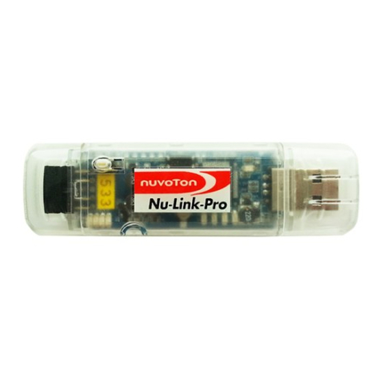
Nuvoton Nu-Link Debug Adapter User Manual Figure 2-1 Nu-Link-Pro Configuration Nu-Link The Nu-Link is a basic debugger and programmer with debugging and online/offline programming functions. As shown in Figure 2-2, the Nu-Link includes an USB port that can be connected to a... -
Page 6: Nu-Link2-Me
Nuvoton Nu-Link Debug Adapter User Manual Figure 2-3 Nu-Link-Me Configuration Nu-Link2-Me The Nu-Link2-Me is a simple debugger and programmer with debugging and online programming functions, which is only shipped with the Nu-Maker kits and can be used stand-alone for developing ®... -
Page 7: Nu-Link Adapter Hardware Specifications
Nuvoton Nu-Link Debug Adapter User Manual Figure 2-5 Rear View of Nu-Link2-Me Configuration Nu-Link Adapter Hardware Specifications The Nu-Link Adapter hardware comparison is shown in Table 2-2. Table 2-2 Nu-Link Adapter Hardware Comparison Device Description Connected to an USB port of a PC to use ✔... - Page 8 Nuvoton Nu-Link Debug Adapter User Manual Nu-Link2-Me. MCUVCC Power Switch (ICEJPR1) ICEVCC Power Switch (ICEJPR2) Table 2-3 SWD I/O Voltage LEDs and SWD Power Output LEDs Status List SWD I/O Voltage LED Power Status 1.8V 2.5V 3.3V 5.0V SWD port I/O and VCC voltage as 1.8V...
- Page 9 Nuvoton Nu-Link Debug Adapter User Manual Offline Programming Completed (Auto mode) Offline Programming Failed Flash Oct 24, 2019 - 9 - Revision V1.01...
-
Page 10: Main Functions
Nuvoton Nu-Link Debug Adapter User Manual Main Functions ® The Nu-Link Adapter provides complete debugging and programming functions for NuMicro Family and supports a number of third-party development tools. The detailed function support is listed in Table 3-1. Table 3-1Nu-Link Adapter Functions... -
Page 11: Debugging
Nuvoton Nu-Link Debug Adapter User Manual Debugging This section briefly describes the debugging function supported by the Nu-Link Adapter. For more details, please refer to the related user manuals. 3.1.1 Debug Mode ® The Nu-Link Adapter supports debugging for the NuMicro Family chips based on the SWD signal interface. - Page 12 Nuvoton Nu-Link Debug Adapter User Manual Figure 3-2 Direct Register Interface Control Related Options in Keil MDK Debug Mode The Direct Register Control Interface for CLK is shown in the left part of Figure 3-3, where the left column shows the register address, the middle column shows the register name, and the right column shows the register value.
-
Page 13: Semihost
Nuvoton Nu-Link Debug Adapter User Manual 3.1.4 Semihost When using the Semihost function, the message of the NuMicro ® Family microcontroller can be output through UART to the debug window by the Nu-Link Adapter. That is, the message is output without shows the debug messages in the “UART #1”... -
Page 14: Programming
Nuvoton Nu-Link Debug Adapter User Manual Programming This section will briefly describe the programming function supported by the Nu-Link Adapter. For more details, please refer to the related user manuals. 3.2.1 Online Programming ® Online Programming means that the Nu-Link Adapter can download the firmware of the NuMicro... -
Page 15: Software Serial Number (Sn)
Nuvoton Nu-Link Debug Adapter User Manual Create APROM, LDROM and DataFlash firmware of Binary or HEX format files. ® NuMicro Family ICP Tool Load Firmware Offline Program NuMicro™ Family Target Board Nu-Link Adapter Computer Figure 3-6 Offline Programming Flow Diagram 3.2.3... -
Page 16: Wide Voltage Programming
Nuvoton Nu-Link Debug Adapter User Manual Wide Voltage Programming The Nu-Link-Pro supports the wide voltage programming function, by which the development software tool can adjust the SWD port voltage as 1.8V, 2.5V, 3.3V, or 5.0V. As shown in Figure 4-2, the pins that can be controlled include VCC, ICE_DAT, ICE_CLK, and /RESET. -
Page 17: Installation And Setup
Nuvoton Nu-Link Debug Adapter User Manual Installation and Setup This chapter introduces how to connect the Nu-Link Adapter to a computer, and how to set the third- party tool to use the Nu-Link Adapter as a debugger and a programmer. -
Page 18: Software Setup
Nuvoton Nu-Link Debug Adapter User Manual Software Setup This section briefly describes required software settings for connecting to the Nu-Link Adapter. For detailed software operation, refer to the related user manuals. 4.2.1 ICP Tool Step 1: Download and install Nuvoton NuMicro ®... - Page 19 Nuvoton Nu-Link Debug Adapter User Manual Step 4: Click Option in the Program section of the ICP Tool Window to open the Program Option form, as shown in Figure 4-5. Step 5: In the Nu-Link Pro IO Voltage section, specify the power voltage of the SWD port for the target chip, and then click OK.
- Page 20 Nuvoton Nu-Link Debug Adapter User Manual Step 6a: After the Connect button is clicked, the ICP Tool will be connected with the Nu-Link Adapter, and a SWD port will be detected. Figure 4-7 shows that the ICP Tool has been connected with the Nu-Link Adapter and a target chip is detected.
-
Page 21: Keil Mdk
Figure 4-9. Figure 4-9 Enable Debug Information for Keil MDK Step 4: Invoke Project → Options for Target → Debug, and make sure the Use:「Nuvoton Nu- Link M0 Debugger option is checked, as shown in Figure 4-10. - Page 22 Specify the SWD port I/O voltage for the target chip; options include 1.8V, 2.5V, 3.3V, and 5V Programmer Settings: Invoke Project → Options for Target → Utilities, select “Nuvoton Nu-Link M0 Step 6: Debugger” when the Use Target Driver for Flash Programming option is enabled, and...
- Page 23 Nuvoton Nu-Link Debug Adapter User Manual Figure 4-12 Keil MDK Programmer Selection Step 7: Click the Settings button to open the Flash Download form, as shown in Figure 4-13 where the user can specify the options before or after programming with the Nu-Link Adapter.
-
Page 24: Iar Ewarm
In the Target tab of the General Options page (through invoking Project → Options), click Step 3: the button in the right of the Device option (make sure the Device option is enabled), and select “Nuvoton → Nuvoton M031AE series” as the target chip (M031AE series is this case), as shown in Figure 4-14 Figure 4-15. - Page 25 Nuvoton Nu-Link Debug Adapter User Manual Debugger and Programmer Settings: Step 4: In the Setup tab of the Debugger page, select Third-Party Driver as the driver, as shown in Figure 4-16. Figure 4-16 Set IAR EWARM as Third-Party Driver for Debugger & Programmer...
- Page 26 Nuvoton Nu-Link Debug Adapter User Manual Figure 4-18 Select.board File for IAR EWARM Driver Plugin File Settings: Step 7: In the Third-Party Driver page, specify the path of the IAR debugger driver plugin “C:\Program Files\Nuvoton Tools\Nu-Link_IAR\Nu-Link_IAR.dll”, as shown in Figure 4-19.
- Page 27 Nuvoton Nu-Link Debug Adapter User Manual Figure 4-20 Specify the Port and Target I/O Voltage Oct 24, 2019 - 27 - Revision V1.01...
-
Page 28: Nueclipse Gcc
Double click on the GDB Nuvoton NuLink Debugging group. The Nuvoton Nu-Link debug configuration appears on the right-hand side. In the Main tab, the name of Project should coincide with the project name. The C/C++ Application should point to the .elf application generated by the build process. - Page 29 Nuvoton Nu-Link Debug Adapter User Manual which uses the interface configuration file named nulink.cfg. In addition, Nuvoton has three different ARM families, such as M0, M4, and M23. The corresponding target configuration files are numicroM0.cfg, numicroM4.cfg, and numicroM23.cfg. For M0 2nd development, the target configuration file would be numicroM0_NS.cfg, as shown in...
- Page 30 Nuvoton Nu-Link Debug Adapter User Manual Figure 4-23 Configuring the Startup Tab Oct 24, 2019 - 30 - Revision V1.01...
-
Page 31: Appendix
Nuvoton Nu-Link Debug Adapter User Manual +Appendix Nu-Link Adapter Operating Current When power is supplied via an USB during online programming, the operating current of Nu-Link Adapter is shown in the table below. Table 5-1 Nu-Link Adapter Operating Current (Online Programming) -
Page 32: Waveform
Nuvoton Nu-Link Debug Adapter User Manual BUSY ICE_DAT START ICE_CLK /RESET ICE_RX/PASS VSS(GND) ICE_TX/FAIL Figure 5-1 SWD Connector Pin Diagrams 5.2.1 Operation sequence and Waveform 1. The Nu-Link2-ME power on. START, BUSY, PASS, and FAIL are set to logic. 2. To start programming, START needs to be set to logic 0 for TSTART, 3. -
Page 33: Revision History
Nuvoton Nu-Link Debug Adapter User Manual Revision History Revision Description Date V1.00 Preliminary version 2012/07/16 V1.01 Delete Nu-Link-Me (On-board Version), Add Nu-Link2-Me. 2019/10/24 Oct 24, 2019 - 33 - Revision V1.01...
Need help?
Do you have a question about the Nu-Link Series and is the answer not in the manual?
Questions and answers