Table of Contents
Advertisement
Quick Links
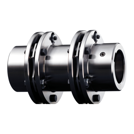
RADEX
Steel lamina couplings types
NN, NANA 1 to 4,
NENA 1 and 2, NENE 1,
NNZ, NNW
according to directive 2014/34/EU
Please observe protection
note ISO 16016.
RADEX
Operating/Assembly instructions
®
-N
Drawn:
2019-07-23 Pz/Wb
Verified:
2019-07-26 Pz
®
-N
®
RADEX
-N type NN
®
RADEX
-N type NANA 1
®
RADEX
-N type NNZ
®
RADEX
-N type NANA 4
®
RADEX
-N type NNW
Replacing:
Replaced by:
KTR-N
47110 EN
Sheet:
1 of 31
Edition:
24
KTR-N dated 2018-07-17
Advertisement
Table of Contents

Related Manuals for KTR-Group RADEX-N


Summary of Contents for KTR-Group RADEX-N
- Page 1 KTR-N 47110 EN ® RADEX Sheet: 1 of 31 Operating/Assembly instructions Edition: ® RADEX Steel lamina couplings types NN, NANA 1 to 4, NENA 1 and 2, NENE 1, ® RADEX -N type NN NNZ, NNW according to directive 2014/34/EU ®...
-
Page 2: Table Of Contents
KTR-N 47110 EN ® RADEX Sheet: 2 of 31 Operating/Assembly instructions Edition: ® is a torsionally stiff flexible steel lamina coupling. It is able to compensate for shaft RADEX misalignment, for example caused by thermal expansion, etc. Table of contents Technical data Advice General advice... -
Page 3: Technical Data
KTR-N 47110 EN ® RADEX Sheet: 3 of 31 Operating/Assembly instructions Edition: Technical data ® ® Illustration 1: RADEX -N type NN Illustration 2: RADEX -N type NANA 1 ® ® Illustration 3: RADEX -N type NANA 2 Illustration 4: RADEX -N type NENA 1 ®... - Page 4 KTR-N 47110 EN ® RADEX Sheet: 4 of 31 Operating/Assembly instructions Edition: Technical data Table 1: Types NN - NANA 1 - NANA 2 - NENA 1 - NENE 1 - NENA 2 Dimensions [mm] Max. finish bore [mm] Size General According to customer specification For dimensions for the setscrews (dimension G and t) see table 4.
- Page 5 KTR-N 47110 EN ® RADEX Sheet: 5 of 31 Operating/Assembly instructions Edition: Technical data ® ® Illustration 7: RADEX -N type NNZ Illustration 8: RADEX -N type NANA 3 ® Illustration 9: RADEX -N type NANA 4 ® Illustration 10: RADEX -N type NNW Dimensions of couplings see table 2, sheet 6.
- Page 6 KTR-N 47110 EN ® RADEX Sheet: 6 of 31 Operating/Assembly instructions Edition: Technical data Table 2: Types NNZ - NANA 3 - NANA 4 - NNW Dimensions [mm] Max. finish bore Size [mm] General Further dimensions of type NANA 3 (L and E ) see table 3.
-
Page 7: Advice
KTR-N 47110 EN ® RADEX Sheet: 7 of 31 Operating/Assembly instructions Edition: Technical data Table 4: Dimensions setscrews Size Number z Size As specified by the customer Number z Table 5: Torque and speed Size 1300 1800 2600 Torque [Nm] 1800 2600 3600... -
Page 8: Safety And Advice Symbols
KTR-N 47110 EN ® RADEX Sheet: 8 of 31 Operating/Assembly instructions Edition: Advice 2.2 Safety and advice symbols This symbol indicates notes which may contribute to Warning of potentially explosive preventing bodily injuries or serious bodily injuries that atmospheres may result in death caused by explosion. This symbol indicates notes which may contribute to Warning of personal injury preventing bodily injuries or serious bodily injuries that... -
Page 9: Coupling Selection
KTR-N 47110 EN ® RADEX Sheet: 9 of 31 Operating/Assembly instructions Edition: Advice 2.5 Coupling selection For a permanent and failure-free operation of the coupling it must be selected according to the selection instructions (according to DIN 740 part 2) for the particular application (see ®... -
Page 10: Assembly
KTR-N 47110 EN ® RADEX Sheet: 10 of 31 Operating/Assembly instructions Edition: Assembly The coupling is generally supplied in individual parts. Before assembly the coupling has to be inspected for completeness. 4.1 Components of the coupling ® Components of RADEX -N type NN Component Number... - Page 11 KTR-N 47110 EN ® RADEX Sheet: 11 of 31 Operating/Assembly instructions Edition: Assembly 4.1 Components of the coupling ® Components of RADEX -N type NNZ Component Number Description Component Number Description Flange hub see table 6 Spacer sleeve Lamina set see table 6 Washer Spacer...
- Page 12 KTR-N 47110 EN ® RADEX Sheet: 12 of 31 Operating/Assembly instructions Edition: Assembly 4.1 Components of the coupling ® Components of RADEX -N type NNW Component Number Description Component Number Description Flange hub see table 6 Spacer sleeve Lamina set see table 6 Washer Intermediate shaft with 2...
-
Page 13: Advice For Finish Bore
KTR-N 47110 EN ® RADEX Sheet: 13 of 31 Operating/Assembly instructions Edition: Assembly 4.2 Advice for finish bore The maximum permissible bore diameters d (see STOP chapter 1 - technical data) must not be exceeded. If these figures are disregarded, the coupling may tear. -
Page 14: Assembly/Disassembly Of Flange Hubs
KTR-N 47110 EN ® RADEX Sheet: 14 of 31 Operating/Assembly instructions Edition: Assembly 4.3 Assembly/disassembly of flange hubs We recommend to inspect bores, shaft, keyway and feather key for dimensional accuracy before assembly. Heating the flange hubs lightly (approx. 80 °C) allows for an easier mounting onto the shafts. -
Page 15: Assembly/Disassembly Of Clamping Ring Hubs
KTR-N 47110 EN ® RADEX Sheet: 15 of 31 Operating/Assembly instructions Edition: Assembly 4.4 Assembly/disassembly of clamping ring hubs The stiffness and dimensions of the shafts (here specifically hollow shafts) have to be selected in a way that sufficient safety against plastic deformation is provided for (if necessary, consult with company KTR). - Page 16 KTR-N 47110 EN ® RADEX Sheet: 16 of 31 Operating/Assembly instructions Edition: Assembly 4.4 Assembly/disassembly of clamping ring hubs Table 8: Tightening torques of clamping screws Size Clamping screws Tightening torque T [Nm] Having started up the coupling the tightening torques of the screws have to be inspected during the usual inspection intervals.
-
Page 17: General Advice For Assembly Of Spacer
KTR-N 47110 EN ® RADEX Sheet: 17 of 31 Operating/Assembly instructions Edition: Assembly 4.5 General advice for assembly of spacer If the coupling is supplied with a transportation lock (optionally), the following has to be observed: The spacer sleeves (steel) have to be removed for further assembly and operation (see illustration 21). -
Page 18: Vertical Assembly/Disassembly
KTR-N 47110 EN ® RADEX Sheet: 18 of 31 Operating/Assembly instructions Edition: Assembly 4.6 Vertical assembly/disassembly If used in potentially explosive atmospheres the setscrews to fasten the hubs as well as all screw connections must be secured against working loose additionally, e. g. conglutinating with Loctite (average strength). -
Page 19: Assembly/Disassembly Of The Lamina Sets, Radex
KTR-N 47110 EN ® RADEX Sheet: 19 of 31 Operating/Assembly instructions Edition: Assembly ® 4.7 Assembly/disassembly of the lamina sets, RADEX -N size 20 - 135 With the assembly please make sure that the lamina sets are installed free from distortion in axial direction. -
Page 20: Assembly/Disassembly Of The Lamina Sets, Radex
KTR-N 47110 EN ® RADEX Sheet: 20 of 31 Operating/Assembly instructions Edition: Assembly ® 4.8 Assembly/disassembly of the lamina sets, RADEX -N size 136 - 336 and 138 - 338 With the assembly please make sure that the lamina sets are installed free from distortion in axial direction. - Page 21 KTR-N 47110 EN ® RADEX Sheet: 21 of 31 Operating/Assembly instructions Edition: Assembly ® 4.8 Assembly/disassembly of the lamina sets, RADEX -N size 136 - 336 and 138 - 338 pitch 8 pitch 9 pitch 10 pitch 11 Illustration 31: Tightening of pressure screws pitch 8 pitch 9 pitch 10...
-
Page 22: Tightening Torques Of Screw Connections On The Lamina Set
KTR-N 47110 EN ® RADEX Sheet: 22 of 31 Operating/Assembly instructions Edition: Assembly 4.9 Tightening torques of screw connections on the lamina set Table 11: Tightening torque of screw connections on the lamina set Size Dimension G [mm] Tightening torque T [Nm] Size Dimension G... - Page 23 KTR-N 47110 EN ® RADEX Sheet: 23 of 31 Operating/Assembly instructions Edition: Assembly 4.10 Displacements - alignment of the couplings Examples of the displacement Illustration 34: combinations specified in illustration 34: Combinations of displacement Example 1: K = 10% K = 80% K = 10%...
-
Page 24: Start-Up
KTR-N 47110 EN ® RADEX Sheet: 24 of 31 Operating/Assembly instructions Edition: Start-up Before start-up make absolutely sure that the transport lock (see illustration 21) have been removed. Before start-up of the coupling, inspect the tightening of the setscrews in the flange hubs, the alignment and the distance dimension E and adjust, if necessary, and also inspect all screw connections for the tightening torques specified. -
Page 25: Breakdowns, Causes And Elimination
KTR-N 47110 EN ® RADEX Sheet: 25 of 31 Operating/Assembly instructions Edition: Breakdowns, causes and elimination ® The below-mentioned failures can result in a use of the RADEX -N coupling other than intended. In addition to the specifications given in these operating/assembly instructions make sure to avoid such failures. The errors listed can only be clues to search for the failures. -
Page 26: Environment And Disposal
KTR-N 47110 EN ® RADEX Sheet: 26 of 31 Operating/Assembly instructions Edition: Breakdowns, causes and elimination Hazard notes for Breakdowns Causes potentially explosive Elimination atmospheres 1) Set the unit out of operation 2) Disassemble the coupling and remove remainders of the steel lamina sets 3) Inspect coupling components and replace Breaking of steel Operating error of the... -
Page 27: Maintenance And Service
KTR-N 47110 EN ® RADEX Sheet: 27 of 31 Operating/Assembly instructions Edition: Maintenance and service The general condition of the coupling can both be monitored at standstill and during operation. If the coupling is tested during operation, the operator must ensure an appropriate and proven test procedure (e. g. stroboscopic lamp, high-speed camera, etc.) which is definitely comparable to testing at standstill. -
Page 28: Enclosure A
KTR-N 47110 EN ® RADEX Sheet: 28 of 31 Operating/Assembly instructions Edition: Enclosure A Advice and instructions regarding the use in potentially explosive atmospheres Types available: NN, NANA 1 to 4, NENA 1 and 2, NENE 1, NNZ, NNW and MK each with flange hubs and each with lamina sets type with 8 pins and closed circular lamina as well as assembly with KTR clamping nuts. -
Page 29: Inspection Intervals For Couplings In Potentially Explosive Atmospheres
KTR-N 47110 EN ® RADEX Sheet: 29 of 31 Operating/Assembly instructions Edition: Enclosure A Advice and instructions regarding the use in potentially explosive atmospheres 10.2 Inspection intervals for couplings in potentially explosive atmospheres Equipment category Inspection intervals For couplings operated in zone 2 or zone 22 the inspection and maintenance intervals of the usual operating/assembly instructions for standard operation apply. -
Page 30: Marking Of Coupling For Potentially Explosive Atmospheres
KTR-N 47110 EN ® RADEX Sheet: 30 of 31 Operating/Assembly instructions Edition: Enclosure A Advice and instructions regarding the use in potentially explosive atmospheres 10.3 marking of coupling for potentially explosive atmospheres ® The ATEX marking of the RADEX -N coupling is applied on the outer sheath or on the front side. The lamina sets are not marked. -
Page 31: Eu Certificate Of Conformity
KTR-N 47110 EN ® RADEX Sheet: 31 of 31 Operating/Assembly instructions Edition: Enclosure A Advice and instructions regarding the use in potentially explosive atmospheres 10.4 EU Certificate of conformity EU Certificate of conformity corresponding to EU directive 2014/34/EU dated 26 February 2014 and to the legal regulations The manufacturer - KTR Systems GmbH, D-48432 Rheine - states that the ®...
Need help?
Do you have a question about the RADEX-N and is the answer not in the manual?
Questions and answers