Advertisement
Table of Contents
- 1 Table of Contents
- 2 Introduction
- 3 Tubing Data
- 4 Tubing Installation
- 5 Product Information
- 6 Vise Clamp Block
- 7 Bend Layout
- 8 Using the Bender
- 9 Making Bends
- 10 Reverse Bends
- 11 Springback
- 12 Determining Changes in Plane and Direction
- 13 Adjustment (Gain) Calculations
- 14 Troubleshooting
- 15 Replacement Parts
- Download this manual
Advertisement
Table of Contents

Related Manuals for Swagelok MS‑HTB‑2

Summary of Contents for Swagelok MS‑HTB‑2
- Page 1 Hand Tube Be nde r Manual...
-
Page 3: Table Of Contents
Contents Introduction . . . . . . . . . . . . . . . . . . . . . . . . . . . 4 Tubing Data . -
Page 4: Introduction
Swagelok tube fittings . Read this manual before using the hand tube bender . Tubing Data The Swagelok hand tube bender bends 1/8, ■ 1/4, 5/16, 3/8, and 1/2 in ., and 3, 6, 8, 10, and 12 mm outside diameter tubing in a variety of wall thicknesses . - Page 5 Metric Tubing High‑quality, soft‑annealed, carbon steel hydraulic tubing DIN2391 or equivalent . Hardness 130 HV (72 HRB) or less . Fully annealed, high‑quality (Type 304, 316 etc .) stainless steel tubing EN ISO 1127 or equivalent . Hardness 200 HV (90 HRB) or less . Approx Carbon Steel Stainless Steel...
-
Page 6: Tubing Installation
Swagelok tube fittings, can provide leak‑tight systems . When installing fittings near tube bends, there must be a sufficient length of straight tubing to allow the tube to be bottomed in the Swagelok tube fitting: Tube OD Required straight tube length (see table) -
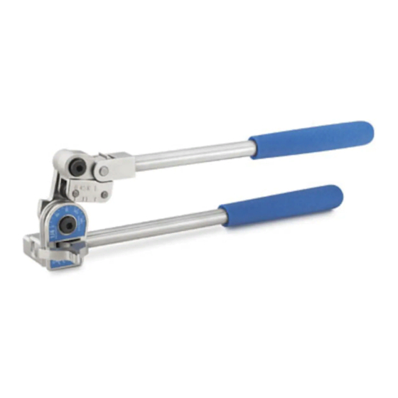
Page 7: Product Information
Product Information Vise clamp block Bender die Clevis Roll dies Short handle Link Roll support Long handle Name plate Tube latch Name plate Straight tube length mark... -
Page 8: Vise Clamp Block
Vise Clamp Block The Swagelok hand tube bender features a vise clamp block which allows the bender to be clamped in a vise . This feature is helpful when bending tube of a hard material or heavy wall thickness, or long pieces... -
Page 9: Bend Layout
Bend Layout This bender can be used to form single, offset, and other bends . This section contains information for measuring and marking the tube prior to bending . Note: Make all marks 360° around the tube . The Measure-Bend Method 1 . - Page 10 Example of the measure‑bend method: A 90° bend 4 inches from the reference mark followed by a 45° bend with 4 inches between bends . 4 in . Vertex Reference mark 4 in . Vertex 45° 1 . Place a reference mark at the end of the tube from which you are beginning the measurements .
- Page 11 Offset Bend Formula The purpose of an offset bend is to change the center line of the run, typically to avoid an obstruction . To determine the length of offset, select the offset angle (E) . Then, multiply the offset dimension (O) by the offset bend allowance (A) .
-
Page 12: Using The Bender
Using the Bender 1 . Swing the short handle up so it is above the bender die . 2 . Open the tube latch . Short handle Tube latch Bender die 3 . Place the tube in the groove of the bender die with the reference mark to the left of the tube latch . - Page 13 5 . Carefully lower the short handle until the roll dies rest gently on the tube while keeping the link straight and parallel to the long handle . Note: Premature bending may occur if the link is not straight and parallel to the long handle .
- Page 14 7 . Align the bend mark with the mark on the roll support that corresponds to the bend angle . 15 30 45 60 75 90 Note: View the marks on the hand tube bender as a 0 to 90 scale when bending other angles .
-
Page 15: Making Bends
Making Bends Bends 90° or Less 1 . Slowly push the short handle down until the 0 on the roll support reaches the desired degree mark on the name plate . Note: Be aware of springback, described on page 19 . Name plate Roll support Short handle... - Page 16 Bends Greater than 90° The right‑angle design of the Swagelok hand tube bender offers maximum leverage when making bends . The bender’s unique design lets you continue using right angle leverage for bends greater than 90° . 1 . Slowly push the short handle down until the 0 on the roll support reaches approximately 90...
- Page 17 3 . Swing the short handle up until it is slightly above perpendicular to the long handle . 4 . Retighten the short handle . This will provide continuous right‑angle leverage for the rest of the bend . Long handle Short handle 5 .
-
Page 18: Reverse Bends
Reverse Bends The Measure-Bend Method Sometimes a multiple bend layout will require that a bend be made in reverse . A reverse bend is made with the reference mark to the right of the tube latch . 1 . Align the bend mark with the marks on the roll support as follows: 90... -
Page 19: Springback
Springback All tubing will exhibit springback after a bend has been completed . The amount of springback depends on the bend angle, bend radius, tubing material, and wall thickness . Experience will help you predict the amount of springback . Expect to allow 1 to 3° of compensation . Note : Verify the bend angle using a template, protractor or against a known angle to ensure the desired bend angle has been achieved . -
Page 20: Determining Changes In Plane And Direction
Determining Changes in Plane and Direction When making multiple bends on a single piece of tube, make sure the bend is made in the correct direction . For bends in the opposite direction of the previous bend, align the tube with the raised short handle (plane A) . -
Page 21: Adjustment (Gain) Calculations
Adjustment (Gain) Calculations When determining tube bend location, adjustment (gain) factors can be considered as an alternate way to achieve the desired layout . Adjustment is the difference in the length of tubing used in a radiused bend compared to the length of tubing required in a sharp bend, when measured from the beginning to the end of the bend . - Page 22 Crawford Hand Tube Bender MS-13-43 C-ELD-334 Example 1/4 in . tubing using a 1/4 in . bender with a 9/16 in . bend radius . Reference mark 3 in . 3 in . (76 .2 mm) (76 .2 mm) 9/16 in . R 2 .5 in .
- Page 23 Fractional Adjustment Calculations Tube OD, in . 5/16 Bend Radius, in . Bend Angle 9/16 9/16 15/16 15/16 1 1/2 30° 1/16 45° 1/16 1/16 1/16 1/16 1/16 1/16 50° 1/16 1/16 1/16 1/16 1/16 55° 1/16 1/16 1/16 60° 1/16 1/16 3/16...
-
Page 24: Troubleshooting
Troubleshooting Tube Bending Defect Cause Solution Wrinkled Undersized bend Increase bend radius radius bend Tube wall thickness Increase wall too thin thickness Flattened Bender is intended Use the correct for use with a larger size bender for the bend tubing diameter tubing being bent Tubing is collapsing Increase wall... - Page 25 Tube Bending Defect Cause Solution Excessive Improper alignment Make sure that the bender die and tubing bend shoe are deformation aligned Excessive pressure Reduce latch on the tube latch pressure (generally visible on softer tubing only)
-
Page 26: Replacement Parts
Replacement Parts Hand Tube Bender Components... - Page 27 Hand Tube Bender Component Descriptions Component Description Bender die Roll support Link Clevis Latch Latch screw Roll die Lead roll die Short handle subassembly Long handle subassembly Handle grip Name plate Lock dowel Clevis pin Spring washer ‑ link Spring washer ‑ latch Shoulder screw Roller subassembly...
- Page 28 Repair Kits Repair kits contain a link, shoulder screws, spring washers, thread locking adhesive, a material safety data sheet, and instructions . Bender Repair Kit Ordering Number Ordering Number MS‑HTB‑2 MS‑HTB‑3M MS‑HTBR‑6ML MS‑HTB‑6M MS‑HTB‑4 MS‑HTBR‑4L MS‑HTB‑4T MS‑HTBR‑4TL MS‑HTB‑5 MS‑HTB‑8M MS‑HTBR‑6TL MS‑HTB‑6T MS‑HTB‑10M MS‑HTB‑8...
- Page 29 Roller Subassemblies A roller subassembly contains a roll support, clevis, roll dies, clevis pin, and lock dowels assembled together at the factory . Bender Roller Subassembly Ordering Number Ordering Number MS‑HTB‑2 MS‑HTB‑2‑100 MS‑HTB‑3M MS‑HTB‑3M‑100 MS‑HTB‑6M MS‑HTB‑6M‑100 MS‑HTB‑4 MS‑HTB‑4‑100 MS‑HTB‑4T MS‑HTB‑4T‑100 MS‑HTB‑5 MS‑HTB‑5‑100 MS‑HTB‑8M...
- Page 30 Hand Tube Bender Components These components may be ordered individually . Bender Ordering Component Ordering Component Number Number MS‑HTB‑2 MS‑HTB‑3M MS‑HTB‑6M MS‑HTB‑4‑008SA MS‑HTB‑4 MS‑HTB‑4T Short handle sub‑ MS‑HTB‑5 assembly MS‑HTB‑8M MS‑HTB‑6‑008SA MS‑HTB‑6T MS‑HTB‑10M MS‑HTB‑8 MS‑HTB‑8‑008SA MS‑HTB‑12M MS‑HTB‑2 MS‑HTB‑3M MS‑HTB‑6M MS‑HTB‑4‑009SA MS‑HTB‑4 MS‑HTB‑4T Long handle...
- Page 31 Bender Ordering Component Component Number Ordering Number MS‑HTB‑2 MS‑HTB‑3M MS‑HTB‑6M 927‑002 MS‑HTB‑4 MS‑HTB‑4T Spring MS‑HTB‑5 washer ‑ link MS‑HTB‑8M 927‑004 MS‑HTB‑6T MS‑HTB‑10M MS‑HTB‑8 927‑006 MS‑HTB‑12M MS‑HTB‑2 MS‑HTB‑3M MS‑HTB‑6M 763‑006 MS‑HTB‑4 MS‑HTB‑4T Shoulder MS‑HTB‑5 screw MS‑HTB‑8M 763‑007 ➀ 763‑007L ➁ MS‑HTB‑6T MS‑HTB‑10M MS‑HTB‑8 763‑008...
- Page 32 Swagelok—TM Swagelok Company © 2009–2014 Swagelok Company Printed in U .S .A ., AGS April 2014, R5 MS‑13‑43...
Need help?
Do you have a question about the MS‑HTB‑2 and is the answer not in the manual?
Questions and answers