Advertisement
Available languages
Available languages
Quick Links
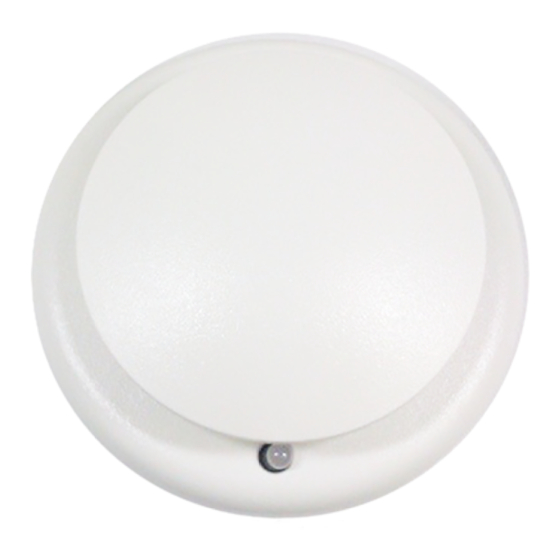
V-PHS Photoelectric and Fixed-Temperature
Heat Detector Installation Sheet
EN FR
EN: Installation Sheet
Operation
The V-PHS Photoelectric and Fixed-Temperature Heat
Detector uses an optical sensing chamber to detect smoke and
a fixed-temperature heat sensor to monitor the temperature of
the air in its surroundings to detect heat from fire. The detector
analyzes the sensor data to determine whether to initiate an
alarm.
The detector is capable of performing comprehensive self-
diagnostics and storing the results. It continuously monitors
changes in sensitivity due to the environment (e.g. dirt, smoke,
temperature, humidity), notifies the control panel of its
condition and issues a dirty sensor warning when it reaches its
preset limit. This notifies the operator of the need for service
while the detector is still operating.
LED operation
The detector provides a bicolor LED that shows its status.
•
Normal: Green LED flashes
•
Alarm/active: Red LED flashes
Electronic addressing
The control panel automatically assigns addresses to the
detectors. Use a laptop computer to address custom
addresses to the detectors. No addressing switches are used.
Installation
Refer to Vigilant Smoke and Heat Detector Application Bulletin
(P/N 3101109) for additional information on detector placement
and spacing.
WARNINGS
•
This detector does not operate without electrical power. As
fires frequently cause power interruption, discuss further
safeguards with the local fire protection specialist.
•
This detector does not sense fires that start in areas
where heat cannot reach the detector. Heat from fires in
walls, roofs, or on the opposite side of closed doors may
not reach the detector.
© 2013 UTC Fire & Security. All rights reserved.
•
Photoelectric detectors have a wide range of sensing
capabilities, but are best suited for detecting slow,
smoldering fires.
•
To ensure proper operation, schedule maintenance
(regular or selected) in accordance with the requirements
of the authority having jurisdiction. Refer to NFPA 72 and
CAN/ULC−S536.
•
To ensure proper operation, store the detector within the
recommended ranges. Allow the detector to stabilize to
room temperature before applying power.
•
Keep the dust cover (supplied) on the detector during
installation and remove it prior to commissioning and
service. The dust cover is not a substitute for removing the
detector during new construction or heavy remodeling.
To install the detector:
1.
Install and wire the detector base using the installation
sheet supplied with the detector base.
2.
Connect the detector to the base by rotating the detector
clockwise until it snaps into the locked position.
To remove the head turn it counterclockwise.
3.
If the head must lock to the base, break away the locking
tab using a pair of pliers. See Figure 1 below.
To remove the detector head after breaking away the
locking tab, insert a small screwdriver into the slot on the
side of the base and press in while simultaneously turning
the detector head counterclockwise.
4.
Log the serial number on the appropriate worksheet.
Figure 1: Breakaway tab
1.
Breakaway tab
1 / 4
Breakaway tab
1
P/N 3101071 • REV 04 • REB 24JAN13
Advertisement

Related Manuals for Vigilant V-PHS

Summary of Contents for Vigilant V-PHS
- Page 1 No addressing switches are used. the detector head counterclockwise. Log the serial number on the appropriate worksheet. Installation Refer to Vigilant Smoke and Heat Detector Application Bulletin Figure 1: Breakaway tab (P/N 3101109) for additional information on detector placement and spacing.
- Page 2 Figure 2: Detector disassembly Maintenance When cleaning is necessary, the sensing chamber of the detector unsnaps for easy field cleaning and service. Note: Only the smoke element of the detector requires cleaning. To clean the detector: Remove the detector from the base. Insert a screwdriver in the small slot where the detector cap connects to the detector body.
- Page 3 Fonctionnement Installation du détecteur : Le détecteur V-PHS utilise une chambre à détection optique Installez et câblez la base du détecteur en suivant les pour localiser la fumée et un capteur de chaleur fixe pour directives sur la fiche d’installation fournie.
- Page 4 Le capteur de fumée ainsi que le capteur de chaleur du détecteur doivent être testés. Pour obtenir nos coordonnées, consultez le site Web www.vigilant-fire.com. Pour tester le détecteur : Avant de procéder au premier test, retirez le pare- poussière et avisez les autorités concernées qu’un service d’entretien est effectué...
Need help?
Do you have a question about the V-PHS and is the answer not in the manual?
Questions and answers