Table of Contents
Advertisement
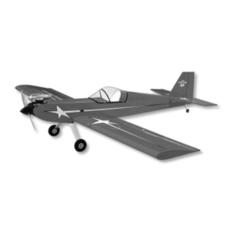
FOUR-STAR 60 ARF ASSEMBLY MANUAL
INTRODUCTION:
SIG's FOUR-STAR 60 ARF combines the classic looks and
performance of Sig's Four-Star series in an almost ready to fly
package. The FOUR-STAR 60 ARF is easy to fly and makes an
ideal choice for your first low wing airplane. Intermediate and
advanced flyers will love the maneuverability and smooth handling
of the Four-Star 60 ARF, making it the sport model you'll want to
take to the flying field every time.
Set the control throws at the suggested low rates for your first
flights, throttle back and enjoy a truly honest, gentle airplane. As
your skill level advances, dial-up the control throws a little to enjoy
a very aerobatic airplane. Inside and outside loops, rolls, inverted
flight, and snap maneuvers are all in the FOUR-STAR 60 flight
envelope.
The FOUR-STAR 60 ARF kit has been engineered to get you into
the air quickly as possible with an R/C model that will truly last.
The airframe has been expertly built and covered with AeroKote
This material is both rugged and easy to repair. The covering trim
scheme is provided on three large peel & stick mylar decal sheets.
This assembly manual has been specifically sequenced to get
your FOUR-STAR 60 ARF assembled and into the air very quickly.
We strongly suggest that you read through the manual first to get
familiar with the various parts and their assembly sequences. The
proper assembly and flying of this aircraft is your responsibility. If
you are new to the sport/hobby of radio control, we urge you to
seek the assistance of a qualified person to help you assemble this
model airplane. If you do not understand a particular assembly
step or sequence, do not guess - find qualified help and use it.
RADIO EQUIPMENT:
The FOUR-STAR 60 ARF requires a standard 4-channel radio
system and five standard servos. We have used and can highly
recommend both the Hitec
these very affordable and reliable radio systems offer all the
features you'll need for this and the many other R/C aircraft in your
future. For reference, this assembly manual shows the installation
of a Hitec
™
radio system with standard servos. In addition, you will
need two aileron 12" servo lead extensions and a 6" aileron servo
Y-harness for connection to the receiver.
R
™
and Airtronics
®
systems. Both of
ENGINE SELECTION:
Engine choices for the FOUR-STAR 60 ARF are many. The
FOUR-STAR 60 ARF has been designed to produce excellent
performance when using the recommended engine sizes. Do not
use an engine larger than recommended.
2-stroke engines are a perfect choice to power your FOUR-STAR
60 ARF. Any plain-bearing or bearing equipped .60 to .75 sport
engine would be a good choice. For example, a great choice
would be the Irvine .61 engine. Like all Irvine engines, the .61 is
powerful, reliable, and quiet. Whatever engine you choose, take
the time to carefully break it in according to the manufacturer's
instructions.
A good running, reliable engine is a minimum
requirement for the enjoyment of this or any R/C model aircraft.
The FOUR-STAR 60 ARF can also use a variety of 4-stroke
engines. Any 4-stroke engine in the .65 - .90 displacement range
should provide plenty of power. An important thing to remember is
that typical 4-stroke engines have their throttle arms usually
located differently than throttle arms on 2-stroke engines. If you
want to power this model with a 4-stroke engine, you will likely
have to install a new, relocated throttle cable tube. While this is not
difficult, it is something to consider when choosing an engine.
™
.
COVERING MATERIAL:
Your FOUR-STAR 60 ARF has been professionally covered using
AeroKote
™
. This material is well known for its ease of application,
light weight, and consistency of color. If you live in a dry climate,
you may notice that some wrinkles might develop after removing
the covered parts from their plastic bags. This is perfectly normal
in low humidity climates. Your model was built and covered in a
part of the world with relatively high humidity and therefore the
wood was likely carrying a fair amount of moisture. When exposed
to drier air, the wood typically loses this moisture, dimensionally
"shrinking" in the process. In turn, this may cause some wrinkles.
However, wrinkles are easy to remove by just using a hobby type
heat iron.
1
Advertisement
Table of Contents

Related Manuals for SIG FOUR-STAR 60


Summary of Contents for SIG FOUR-STAR 60
- Page 1 Whatever engine you choose, take of the Four-Star 60 ARF, making it the sport model you'll want to the time to carefully break it in according to the manufacturer’s take to the flying field every time.
- Page 2 1 each 2-56 x 3/4” Threaded Brass Coupler; for carb end of throttle pushrod 3 each 2-56 Nylon R/C Links; for elevator (1), rudder (1), A selection of glues - SIG Thin and Thick CA and throttle (1) SIG Kwik-Set 5-Minute Epoxy 3 each 2-56 Solder R/C Links;...
-
Page 3: Assembling The Wing
- leave it in place for now. ASSEMBLING THE WING: The wing on the FOUR-STAR 60 ARF is designed as a strong, easy to assemble one piece unit. For precise control there is one servo mounted in each wing panel to control the ailerons. - Page 4 length required is 21”. A 12” extension cable will usually provide control surfaces on this model. Press the six CA hinges into the sufficient length. Plug the extension cable into the servo and slots in the aileron. Use pins in the center of each hinge to keep secure well with tape.
- Page 5 10 minutes before flexing the aileron. Any spilled glue can be removed with Sig Debonder. 3) Attach the 4-40 link and pushrod to the second to last hole in the aileron servo output arm.
- Page 6 3/16” 7) Remove the pushrod from the servo and remove the solder 2) Use Sig Slow Cure epoxy to join the two wing panels link from the control horn. Cut the pushrod at the mark. Slip the solder link onto the end of the pushrod so that the end of the rod together.
-
Page 7: Assembling The Fuselage
Pushrod exit Antenna exit 2) Carefully remove the covering from the bottom of the wing 3 - Three screw holes for mounting landing gear...Located on the bottom of the fuselage just ahead of the wing at the location of the plywood plates by using a sharp knife to cut opening. -
Page 8: Engine And Fuel Tank Installation
aluminum landing gear. Use a phillips screw driver and a small to 90 , to reach the top of the tank. Adjust the length of the wrench to firmly tighten the nuts to the screws on the landing gear. internal silicon fuel tubing to allow free movement of the fuel pick-up inside the tank. - Page 9 Press the neck into the firewall hole. Allow the silicon sealant to and drill the four required holes in the mounts for your engine. If cure before applying any pressure to the fuel lines. you are using 6-32 x 1 1/2” screws and lock nuts (not supplied) to mount your engine, use a 5/32"...
-
Page 10: Tail Surface Installation
pushrod housing should be glued into position in the holes in the 2) Prepare to install the elevator joiner wire into the inboard firewall and former. leading edges of both elevator halves. Start by first removing a strip of covering material over the channel and hole that are 9) Now install the motor as described in step #4 of this section. - Page 11 8) The horizontal stabilizer is now glued in place into the rear of the fuselage. We suggest using 5-minute epoxy for this job to allow time to position the stab accurately and make any final adjustments that might be needed. Allow the glue to set completely.
-
Page 12: Radio Installation
gluing. The covering should be trimmed away 1/16” inside the drawn lines. It is extremely important that you cut the covering only and not the balsa underneath. Do not cut into the balsa. Also remove the covering from the sides of the fin in the location of the tail fairings. - Page 13 system. We have found it handy to label these leads for easy 2) Insert the unthreaded end of the 3 1/2" control rod into one identification when plugging them into the receiver. of the 36" nylon control tubes, up to the threads on the rods. Thread the rod into the tube about 3/16"...
-
Page 14: Spinner Assembly
1) Locate the black SIG spinner assembly from the kit contents. This spinner is easy to install, lends a great look to your finished FOUR-STAR 60 ARF and is ready for use with APC propellers! Choose the correct adapter ring for your engine. - Page 15 Balancing this or any R/C model airplane is critical to its ultimate success in the air. The recommended starting balance point for the FOUR-STAR 60 ARF, is located 3-5/8” behind the leading edge CONTROL SURFACE TRAVEL CHART: of the wing. This measurement corresponds to the center of the main spar.
- Page 16 - do not slam the if the model hangs tail down from level, it is tail heavy. If either of throttle full open all at once. As the FOUR-STAR 60 ARF begins these conditions exist, they should be corrected.
-
Page 17: Academy Of Model Aeronautics
SIG MANUFACTURING COMPANY, INC. is totally committed to your success in both assembling and flying the FOUR-STAR 60 ARF kit. Should you encounter any problem building this kit or discover any missing or damaged parts, please feel free to contact us by mail or telephone.
Need help?
Do you have a question about the FOUR-STAR 60 and is the answer not in the manual?
Questions and answers