Axis 2N Indoor View User Manual
Hide thumbs
Also See for 2N Indoor View:
- Configuration manual (128 pages) ,
- User manual (117 pages) ,
- Installation manual (78 pages)
Table of Contents
Advertisement
Advertisement
Table of Contents

Related Manuals for Axis 2N Indoor View


Summary of Contents for Axis 2N Indoor View
- Page 1 ® 2N Indoor View User guide Firmware: 2.29 Version: 2.29 www.2n.cz...
- Page 2 The 2N TELEKOMUNIKACE a.s. is a Czech manufacturer and supplier of telecommunications equipment. The product family developed by 2N TELEKOMUNIKACE a.s. includes GSM gateways, private branch exchanges (PBX), and door and lift communicators. 2N TELEKOMUNIKACE a.s. has been ranked among the Czech top companies for years and represented a symbol of stability and prosperity on the telecommunications market for almost two decades.
-
Page 3: Table Of Contents
Content: 1. Product Description 1.1 Product Description 1.2 Differences between Models and Associated Products 1.3 Terms and Symbols Used 1.4 Safety Precautions 2. Description and Installation 2.1 Before You Start 2.2 Quick installation guide 2.3 Installation Conditions 2.4 2N® Indoor View LAN Location via 2N® Network Scanner 2.5 IP Address Lookup 3. -
Page 4: Product Description
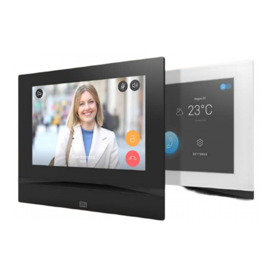
1. Product Description ® In this section, we introduce the Indoor View product, outline its application options and highlight the advantages following from its use. The section also includes safety precautions. 1.1 Product Description 1.2 Differences between Models and Associated Products 1.3 Terms and Symbols Used 1.4 Safety Precautions 2N TELEKOMUNIKACE a.s., www.2n.cz... - Page 5 1.1 Product Description ® Indoor View is a stylish, compact-design indoor IP/SIP unit providing audio and video communication with the 2N IP intercoms . The device includes a 4 mm enhanced glass touchscreen panel, Speakerphone, high-quality microphone with excellent audibility and intelligibility properties, Ethernet LAN interface and induction loop and ®...
-
Page 6: Differences Between Models And Associated Products
Associated Products 2N ® Indoor View indoor units 2N Part No. 91378601 ® Indoor View – black Axis Part No. 02087-001 Indoor answering audio/video unit with touchscreen designed for all 2N IP intercoms 2N Part No. 91378601WH ® Indoor View –... - Page 7 Part Numbers: ® Indoor Touch 2.0 – black 2N Part No. 91378375 WiFi version (third and fourth Part Nos.) Axis Part No. 01668-001 2N Part No. 91378376 ® Indoor Touch 2.0 , an elegant indoor touch Axis Part No. 01670-001...
- Page 8 Part Numbers: ® Indoor Touch 2.0 – white 2N Part No. 91378375WH WiFi version (third and fourth Part Nos.) Axis Part No. 01669-001 2N Part No. 91378376WH ® Indoor Touch 2.0 , an elegant indoor touch Axis Part No. 01671-001...
- Page 9 2N Part No. 91378501WH ® Indoor Compact – white Axis Part No. 01936-001 Indoor answering audio/video unit with touchscreen designed for all 2N IP intercoms 2N Part No. 91378401 ® Indoor Talk – black Axis Part No. 01698-001 Indoor answering audio unit with touchscreen designed for all 2N IP intercoms 2N Part No.
- Page 10 Mounting Accessories 2N Part No. 91378800 Installation box for 2N indoor answering units for installation in a wall or plasterboard. Axis Part No. 01700-001 ® Not included in the Indoor View package. 2N Part No. 91378802 Stand for the 2N indoor answering unit.
- Page 11 VoIP Phones 2N Part No. 91378358 Grandstream GXV3240 VoIP video telephone Axis Part No. 01421-001 GXV3240 is the successor to the popular GXV3140 model, which provides comfortable video calls in the IP network. Touchscreen and keypad control. 2N Part No.
-
Page 12: Terms And Symbols Used
1.3 Terms and Symbols Used The following symbols and pictograms are used in the manual: Safety Always abide by this information to prevent persons from injury. Warning Always abide by this information to prevent damage to the device. Caution Important information for system functionality. Useful information for quick and efficient functionality. -
Page 13: Safety Precautions
1.4 Safety Precautions The manufacturer reserves the right to modify the product in order to improve its qualities. The manufacturer continuously responds to the clients' requirements by ® improving the software. Refer to the www.2n.cz company websites for the latest Indoor View firmware and User Manual. -
Page 14: Description And Installation
2. Description and Installation ® This section describes how to install and connect Indoor View properly. Here is what you can find in this section: 2.1 Before You Start 2.2 Quick installation guide 2.3 Installation Conditions 2.4 2N® Indoor View LAN Location via 2N® Network Scanner 2.5 IP Address Lookup 2N TELEKOMUNIKACE a.s., www.2n.cz 14/112... -
Page 15: Before You Start
2.1 Before You Start Package Completeness Check Please check the product delivery before starting installation: Contents: ® Indoor View External power and doorbell button terminals Certificate of ownership 2.5 mm hexagon key wrench Quick Start manual display cleaning cloth 2N TELEKOMUNIKACE a.s., www.2n.cz 15/112... - Page 16 Front Layout Display Microphone Speaker Anchoring holes 2N TELEKOMUNIKACE a.s., www.2n.cz 16/112...
- Page 17 Backside Connectors Output for connection of an external induction loop Reset button Doorbell button input 12 V / 1 A DC power supply input Ethernet ® Indoor View is designed for flush mounting (brick, plasterboard, wood). Use the flush mounting box (Part No. 91378800), which is not included in the package. Alternatively, the product can be mounted into a desk stand (Part No.
- Page 18 2N TELEKOMUNIKACE a.s., www.2n.cz 18/112...
- Page 19 Cut a circular hole in the wall of the diameter of 103 mm and depth of 50 mm before installation. It is assumed that all necessary cables of the maximum length of 25 cm will lead to the hole. Put the flush mounting box in the hole to make sure that the hole is deep enough.
-
Page 20: Quick Installation Guide
2.2 Quick installation guide ® Remove the cover from the walled-in Indoor View flush mounting box. Remove the pre-prepared cabling, UTP cable, doorbell twin cable and power supply cable. Shorten the cables to 150 mm or less as required. Connect the doorbell twin cable or power supply cable to the connector provided. - Page 21 it clicks onto the levelling pins, The pins allow for a 5–6 ° inclination on either side for accurate horizontal levelling. Apply the box screw nuts with the hexagon key wrench ® provided. Level Indoor View with a water level and tighten the screws gently. ®...
-
Page 22: Installation Conditions
2.3 Installation Conditions ® Make sure that the following Indoor View installation conditions are met: There must be enough space for the device installation. The device is designed for vertical wall mounting (perpendicular to the floor) in the height of up to 120 cm above the floor. If necessary, operate the device in a position other than as aforementioned for a short time only, for quick testing purposes in a servicing center, for example. - Page 23 PoE Supply Connection ® Use a standard straight RJ-45 terminated cable to connect Indoor View to the Ethernet. The device supports the 10BaseT and 100BaseT protocols. Caution Factory reset results in a change of the Ethernet interface configuration! A defective Ethernet cable may lead to a high packet loss in the Ethernet and subsequent instability and poor call quality! Warning Do not connect any external power supply if PoE is used and vice versa.
-
Page 24: Indoor View Lan Location Via 2N® Network Scanner
2.4 2N® Indoor View LAN Location via 2N® Network Scanner ® Indoor View is configured via the administration web server. Connect the device to the LAN IP and make sure it is properly powered. 2N ® Network Scanner Description ® The application helps find the IP addresses of all the Indoor View devices in the... - Page 25 Once started, the application begins to automatically search for all the 2N IP intercoms ® ® in the LAN including their smart extensions ( Indoor View, Indoor Compact ® ® Indoor Talk 2N Indoor Touch ), which are DHCP/statically assigned IP addresses. All the devices are displayed in a table ®...
- Page 26 ® IP Network Scanner IP Address Change 2N TELEKOMUNIKACE a.s., www.2n.cz 26/112...
-
Page 27: Ip Address Lookup
2.5 IP Address Lookup ® To look up the device IP address, take the following steps: Use the free 2N Network Scanner application or view the information on the device display. ® ® To find the Indoor View IP address via the Network Scanner , follow the ®... - Page 28 Dynamic/Static IP Address Switching ® Indoor View is connected to the LAN and has to be assigned a valid IP address or obtain the IP address from the LAN DCHP server. Configure the IP address and DHCP in the System / Network menu. Use DHCP server –...
- Page 29 Default gateway – address of the default gateway, which provides communication with off-LAN equipment. Primary DNS – primary DNS address for domain name-to-IP address translation. Secondary DNS – secondary DNS address where the primary DNS is unavailable. 2N TELEKOMUNIKACE a.s., www.2n.cz 29/112...
-
Page 30: Configuration
3. Configuration Login ® Fill in the Indoor View address or domain name into the internet browser. to display the login screen. The default login user name and password are as follows: Username: Admin Password: 2n Should the login screen fail to appear, you must have typed a wrong IP address/port ®... -
Page 31: Factory Reset
3.1 Factory Reset Reset Button Located among the main unit connectors, the Reset button helps you reset the factory default values, restart the device, find the device IP address and switch the static /dynamic mode. IP Address Finding Follow the instructions below to identify the current IP address Press and hold the RESET button. - Page 32 Wait until the red and green LEDs go on simultaneously on the device and the acoustic signal can be heard (approx. 15–35 s). Wait until the red LED goes off and the acoustic signal can be heard (approx. for another 3 s). Release the RESET button.
- Page 33 Factory Reset Follow the instructions below to reset the factory default values Press and hold the RESET button. Wait until the red and green LEDs go on simultaneously and the acoustic signal can be heard (approx. 15–35 s). Wait until the red LED goes off and the acoustic signal can be heard (approx.
- Page 34 Note ® For the Indoor View , the time interval between a quick press of the RESET button and reconnection of the device to the network is 20 s. 2N TELEKOMUNIKACE a.s., www.2n.cz 34/112...
-
Page 35: Software Configuration
3.2 Software Configuration Start Screen ® The start screen is displayed when you log in to the Indoor View web interface. Use the button in the left-hand upper corner on each of the following web interface pages to return to this screen anytime. The screen header includes the device name (refer to the Display Name parameter in the Services / Phone / SIP menu). - Page 36 3.2.2 Directory 3.2.3 Services 3.2.4 Hardware 3.2.5 System 2N TELEKOMUNIKACE a.s., www.2n.cz 36/112...
- Page 37 3.2.1 Status Status menu provides clear status and other current information on the device. The menu consists of three tabs: Device Services Events 3.2.1.1 Device 3.2.1.2 Services 3.2.1.3 Events 3.2.1.1 Device Device The tab displays information on the model, its features, firmware and bootloader versions, etc.
- Page 38 Factory Certificate Installed – specify the user certificate and private key to validate the intercom right to communicate with the ACS. Locate device – optical and acoustic signalling of a device. Optical signalling is ® ® possible only if the device is equipped with control backlight ( IP Verso ®...
- Page 39 Services The Services tab displays the status of the network interface and selected services. 2N TELEKOMUNIKACE a.s., www.2n.cz 39/112...
- Page 40 3.2.1.3 Events Events The tab displays the last 500 events captured by the device. Every event includes the capturing time and date, event type and detailed description. The events can be filtered by type in a dropdown menu above the event log. 2N TELEKOMUNIKACE a.s., www.2n.cz 40/112...
- Page 41 3.2.2 Directory Directory is one of the crucial parts of the device configuration. It helps add new devices (2N IP intercoms and other answering units) and provides essential information on them. Up to 200 devices can be added to the directory. The Search function works as a fulltext search in names and phone numbers.
- Page 42 Device Name – enter the device name for the selected Phone Book position. This parameter is optional and helps you find items in the Phone Book more easily. Displayed Icon – display the reception desk symbol or a standard symbol. Device Type –...
- Page 43 Start call with a doorbell button press – a phone call to this device will be set up after the alarm call button is pressed. Set the doorbell alarm call function in HW / Digital inputs / Doorbell button. Code 1, 2, 3, 4 – enter the code assigned to unlock button #1, #2, #3, #4. It is used for remote unlocking of the entrance door, for example.
- Page 44 Here is what you can find in this section: 3.2.3.1. Phone 3.2.3.2 Unlocking 3.2.3.3 User Sounds 3.2.3.4 Web Server 3.2.3.5 Weather 3.2.3.1. Phone ® Phone is an essential function of Indoor View allowing you to establish ® connections to other IP network terminals. Indoor View supports the extended SIP.
- Page 45 Video – video codec and SDP codec settings. 2N Indoor Units – general parameters and count of identified LAN devices. SIP 1 and SIP 2 ® Indoor View helps you configure one SIP account. Display Name – set the name to be displayed as CLIP on the called party's phone.
- Page 46 Proxy Address – set the SIP Proxy IP address or domain name. Proxy Port – set the SIP Proxy port (typically 5060). Backup Proxy Address – set the backup SIP Proxy IP address or domain name. The address is used where the main proxy fails to respond to requests. Backup Proxy Port –...
- Page 47 SIP Transport Protocol – set the SIP communication protocol: UDP (default), TCP or TLS. Local SIP Port – set the local port for the device for SIP signaling. A change of this parameter will not be applied until the device is restarted. The default value is 5060.
- Page 48 Do Not Play Incoming Early Media – disable playing of the incoming audio stream before the call sent by some PBXs or other devices is picked up (early media). A standard local ringtone is played instead. QoS DSCP Value – set the SIP packet priority in the network. The set value is sent in the TOS (Type of Service) field in the IP packet header.
- Page 49 Call Receiving Mode (SIP 1, SIP 2) – set the way of receiving incoming calls. The following three options are available: Always busy – the device rejects incoming calls. Manual answering – the device rings to signal incoming calls and the user can press a keypad button to pick up.
- Page 50 Audio Enable/disable the use of audio codecs for call setups and set their priorities. The tab below helps you define how DTMF characters shall be sent from the intercom. Check the opponent’s DTMF receiving options and settings to make the function work properly.
- Page 51 In-Band (Audio) – enable classic DTMF dual tone receiving in the audio band. RTP (RFC-2833) – enable DTMF receiving via RTP according to RFC-2833. SIP INFO (RFC-2976) – enable DTMF receiving via SIP INFO messages according to RFC-2976. QoS DSCP Value – set the audio RTP packet priority in the network. The set value is sent in the TOS (Type of Service) field in the IP packet header.
- Page 52 Local Calls Enable Local Calls – enable calls between 2N devices in the LAN. With this function off, the other LAN devices cannot locate this device, i.e. cannot call the device in the device:device_ID format. Device ID – set the device ID to be displayed in the LAN device list in all the 2N devices in one and the same LAN.
- Page 53 LAN Device count – display the number of local devices in the network. Show LAN devices list – display a detailed list of local devices in the network. 3.2.3.2 Unlocking ® Unlocking is another function of Indoor View , which sets the remote door unlocking parameters.
- Page 54 3.2.3.3 User Sounds ® Indoor View signals variable operational statuses with a sequence of tones. If the standard signaling tones do not meet your requirements, you can modify them. The device allows you to modify sound signaling for the following states: Ringtone before call pickup Ringing tone Busy tone...
- Page 55 Ringback Tone – set the sound to be played when the called user is ringing. The PBX ringtone is preferred to the user ringtone in the device. Call Busy Tone – set the tone to be played when the called user is busy. Call Hang-Up Signaling –...
- Page 56 3.2.3.4 Web Server ® Indoor View can be configured using a common browser that approaches the web server integrated in the device. The HTTPS protocol is used for the browser - device communication. Enter the login user name and password first. The default values are admin respectively.
- Page 57 HTTP Port – set the web server port for HTTP communication. The port change will not be applied until the device is restarted. HTTPS Port – set the web server port for HTTPS communication. The port change will not be applied until the device is restarted. Minimum Allowed TLS Version –...
- Page 58 3.2.3.5 Weather Weather service offers display of information about the current weather for the ® selected location on the home screen of the Indoor View Display weather – information about the current weather will be shown on the device display. Location –...
- Page 59 Update status – displays the update status of data from the Open Weather server. Last update – specifies the precise date of last update of data from the OpenWeather server. Location found – weather forecast location found by the OpenWeather server. Data source –...
- Page 60 3.2.4 Hardware Here is what you can find in this section: 3.2.4.1 Audio 3.2.4.2 Display 3.2.4.3 Digital Inputs 2N TELEKOMUNIKACE a.s., www.2n.cz 60/112...
- Page 61 3.2.4.1 Audio ® Indoor View is equipped with a speaker. Set the phone call and state signaling volume control in this configuration section. Master Volume controls the general device volume including call volume, signaling tone volume, and so on. Consider the noise level of the ambient environment while setting this parameter.
- Page 62 Warning Tone Volume – set the volume of warning and signaling tones. The volume values are relative against the set master volume. Suppress Warning Tones – suppress signaling of the following operational states: Internal application started, IP address received and IP address lost. User Sound Volume –...
- Page 63 Language – set the language for the texts to be displayed. Choose one of the seven pre-defined languages (CZ, EN, DE, FR, ES, IT, RU). Date Format – set the date format to be displayed. Time Format – set the time format to be displayed. Screen Lock Enabled –...
- Page 64 Original language – download a preset XML file with all the texts to be displayed. It is an XML file with all the texts to be displayed. Note If none of the pre-defined languages is convenient for you, proceed as follows: Download the original language file (English).
- Page 65 3.2.4.3 Digital Inputs This subsection describes the digital input options of the device. Doorbell Button Function – select doorbell function (doorbell, alarm call). The button is used either as a classical doorbell or for alarm call activation. 2N TELEKOMUNIKACE a.s., www.2n.cz 65/112...
- Page 66 3.2.5 System Here is what you can find in this section: 3.2.5.1 Network 3.2.5.2 Date and Time 3.2.5.3 Certificates 3.2.5.4 Auto Provisioning 3.2.5.5 Syslog 3.2.5.6 Maintenance 2N TELEKOMUNIKACE a.s., www.2n.cz 66/112...
- Page 67 3.2.5.1 Network ® Indoor View is connected to the LAN and has to be assigned a valid IP address or obtain the IP address from the LAN DCHP server. The Network section helps you configure the IP address and DHCP. ®...
- Page 68 List of Parameters Network Basic Use DHCP server – enable automatic obtaining of the IP address from the LAN DHCP server. If the DHCP server is unavailable or otherwise inaccessible in your LAN, use the manual network settings. Static IP Address – static IP address of the device. The address is used together with the parameters below unless Use DHCP server is enabled.
- Page 69 VLAN Enabled – enable the virtual network support (VLAN according to 802.1q). Remember to set the VLAN ID too. VLAN ID – choose a VLAN ID from the range of 1–4094. The device shall only receive packets with the set ID. An incorrect setting may result in a connection loss and subsequent factory reset.
- Page 70 Trace The Trace tab helps you trigger capturing of incoming and outgoing packets via the 2N ® Indoor View LAN interface. The captured packets are stored in a 4 MB buffer. When the buffer storage capacity is full, the oldest packets are rewritten automatically. You are recommended to keep the video stream bit rate below 512 kbps while capturing packets.
- Page 71 3.2.5.2 Date and Time ® Indoor View is equipped with a real time clock to back up the device for even a ® few days in case of power outage. Click Synchronise to synchronise your Indoor View time with your PC time value any time. ®...
- Page 72 List of Parameters Synchronize with browser – click the button to synchronize the device time with your current PC time value. Time Zone – set the time zone for your installation site. to define time shifts and summer/winter time transitions. Time Zone Rule –...
- Page 73 3.2.5.3 Certificates ® Some Indoor View LAN services use the secure TLS protocol for communication with the other LAN devices. This protocol prevents third parties from eavesdropping on or modifying call contents. TLS is based on one/two-sided authentication, which requires certificates and private keys. ®...
- Page 74 – browser communication is secure, but the browser notifies ® you that it cannot authenticate the 2N Indoor View certificate. Refer to the tables below for the current list of trusted and user certificates: 2N TELEKOMUNIKACE a.s., www.2n.cz...
- Page 75 Click to upload a certificate saved on your PC. Select the certificate (or private key) file in a dialogue window and click Upload . Press to remove a certificate from ® Indoor VIew Caution Note that a certificate with a private RSA key longer than 2048 bits may r e j e c t e d The private key file or password has not been accepted by the device! For certificates based on elliptic curves use the secp256r1 (aka...
- Page 76 3.2.5.4 Auto Provisioning ® Indoor View help you update firmware and configuration manually, or automatically from a storage on a TFTP/HTTP server selected by you according to predefined rules. ® The TFTP and HTTP server addresses can be configured manually. The 2N Indoor View support automatic identification of the local DHCP server address (Option 66).
- Page 77 Active Profile – select one of the pre-defined profiles (ACS), or choose a setting of your own and configure the ACS connection manually. Next Synchronization in – display the time period in which the device shall contact a remote ACS. Connection Status –...
- Page 78 3.2.5.5 Syslog ® Indoor View allows you to sends syslog messages including relevant device state and process information to a syslog server for recording and further analysis or auditing of the device observed. It is unnecessary to configure this service for common operations.
- Page 79 General overview of local syslog messages. 2N TELEKOMUNIKACE a.s., www.2n.cz 79/112...
- Page 80 3.2.5.6 Maintenance This menu helps you maintain the device configuration and firmware. You can back up and restore all the parameters, upgrade firmware and/or factory reset the device. Restore Configuration – restore configuration from a previous backup. Press the button to display a dialogue window to select a configuration file and upload it to the device.
- Page 81 Reset Configuration – reset all the device parameters except for the LAN parameters. To reset the device completely, use the jumper or press Reset. Upgrade firmware – upload a new firmware version to the device. Press the button to display a dialogue window to select the proper firmware file. Once the firmware is uploaded, the device is restarted automatically and becomes fully operational with a new firmware version.
- Page 82 Send anonymous statistics data – enable sending of anonymous statistic data on device usage to the manufacturer. No such delicate information as passwords, access codes or phone numbers are included. This information helps 2N TELEKOMUNIKACE a.s. improve software quality, reliability performance.
-
Page 83: Device Control Via Display
4. Device Control via Display Sleep Mode The device will automatically go into sleep mode if there is no activity (after selection of the timeout from 15 s to 10 min). 2N TELEKOMUNIKACE a.s., www.2n.cz 83/112... - Page 84 Home Page The Home page is set as the introductory screen, which is displayed when the device is switched from the Idle mode by the touch of a finger. It shows the current date, time and temperature, gives you access to the Access Logs, Directory and Settings menus and allows you to activate the Do Not Disturb mode directly.
- Page 85 Icon Description Incoming call ringtone volume up Incoming call ringtone volume down Incoming call ringtone volume mute Value up Value down Microphone mute in call Locked, screen lock Unlocked, screen lock activated/deactivated Camera Preview Camera 1 Camera 2 Back Move up Move down 2N TELEKOMUNIKACE a.s., www.2n.cz 85/112...
- Page 86 The device will automatically go into sleep mode if there is no activity (after selection of the timeout from 15 s to 10 min). In this mode, the device only shows the date, time and current weather. 2N TELEKOMUNIKACE a.s., www.2n.cz 86/112...
-
Page 87: Access Logs
4.1 Access Logs Press the button to display the Call list. The menu provides a list of all accomplished calls including date, time, status (ougoing/incoming/missed) and information on from/to which destination the call was made. ® You can choose any of the following actions from the Indoor View call list: Return to Home page... -
Page 88: Directory
4.2 Directory Find the Directory menu under the phone earpiece icon The menu provides a list of destinations that can be called. The destinations include their names and the device type they are equipped with. The Directory provides either a list view where you can scroll up/down, or a tile view where you can browse from right to left to choose a destination. - Page 89 The camera switching function is only displayed if it has been activated and properly configured in the intercom. Set the Directory via the web interface in the Directory / Device section. You can add a device manually, by clicking on the device adding icon or automatically by clicking the registered device searching icon .
-
Page 90: Settings
4.3 Settings Press the button on the home screen to display the Device Settings section. The settings menu can be used for local device settings. It contains 8 sections: Display Brightness – sets the value of display backlighting. Screen timeout – timeout after which the device automatically goes into Sleep Mode if there is no activity. - Page 91 Ringtone Volume – set the incoming call ringtone volume. Call Volume – set the phone call volume. Ringtone – sets the ringtone for incoming calls on the device. Doorbell tone – set the tone to be played when the doorbell is used. Set date and time automatically –...
- Page 92 Set Time Zone – set the time zone for your installation site to define time shifts and summer/winter time transitions. Time Format – set the time format to be displayed. Date Format – set the date format to be displayed. Language –...
- Page 93 Do Not Disturb mode – switches Do Not Disturb mode on/off. This allows you to switch off the ringtone for the incoming call for the period of time when this mode is active. By default, the DND mode does not apply to doorbell notification, i.e.
- Page 94 This section provides basic information on the device (serial number, MAC address, FW version, IP address, My2N ID). 2N TELEKOMUNIKACE a.s., www.2n.cz 94/112...
-
Page 95: Operational Statuses
5. Operational Statuses This section describes the user scenarios and states that may occur during operation, including the user options and expected results of actions. Status and Description User Actions Navigation Actions and Result Sleep Mode Only the current date, time and weather are shown on the display. - Page 96 Status and Description User Actions Navigation Actions and Result Home Page Device is in relax mode. Display Press the blue The list of all available Directory backlit phone devices is displayed. earpiece button Display Call list Button pressed The list of all accomplished calls is displayed.
- Page 97 Status and Description User Actions Navigation Actions and Result Move up and Press display The list scrolls up or down in list with finger and down in the list. Once slide up or down the end of the list has been reached, scrolling stops.
- Page 98 Status and Description User Actions Navigation Actions and Result Directory The device displays a list of destinations that can be called. The destinations include their names and the device type they are equipped with. Return to Home Press back Home page is displayed. page button Scroll up and...
- Page 99 Status and Description User Actions Navigation Actions and Result Incoming Call The device is playing the selected ringtone. The display shows the camera view if available, CLIP and Incoming call message. Pick up call Touch of the The connection is display established and the In call mode is switched...
- Page 100 Status and Description User Actions Navigation Actions and Result Outgoing Call The device is playing the ringtone. The display shows the camera view if available, called device ID and Outgoing call message. End call Press the call The outgoing call is discontinued and Home end button page is returned to.
- Page 101 Status and Description User Actions Navigation Actions and Result In Call The display shows the camera view if available, or the called device ID if no camera is available. A timer is running at the view. Mute call Press the Mute The device is in the In call mode but sound is button...
- Page 102 Status and Description User Actions Navigation Actions and Result Increase and Button pressed The volume of the call is decrease call increased or decreased volume by one level at each required volume individual press of + or - selected by .
- Page 103 Status and Description User Actions Navigation Actions and Result Incoming call in Do Not The device does not play the selected ringtone. The display Disturb mode shows the camera view if available, CLIP and Incoming call message. Pick up call Press the call The call is connected.
-
Page 104: Technical Parameters
6. Technical Parameters Power Supply Type: 12 V DC +/-10 % adapter or PoE 802.3af Recommended power supply: 12 V / 1 A Polarity reversal protection:yes User Interface Controls: capacitive touch panel Display: 7 ´´ with 1024 x 600 pixel resolution Service:RESET button with long press option for factory reset Signalling protocol SIP (UDP, TCP, TLS) - Page 105 Input type: switching contact (button/relay) Contact type: normally open (NO) Contact parameters: up to 50 V / 5 mA, DC Mechanical Parameters Dimensions (w x h x d): 193 x 157 x 50 mm Weight: 555 g Operating temperature: 0 to 50 °C Relative humidity: 10 to 90 % non-condensing Storing temperature: -20 to 70 °C Recommended altitude: 0 –...
-
Page 106: Supplementary Information
7. Supplementary Information ® This section provides supplementary information on the Indoor View product. Here is what you can find in this section: 7.1 Troubleshooting 7.2 Directives, Laws and Regulations - General Instructions and Cautions 2N TELEKOMUNIKACE a.s., www.2n.cz 106/112... -
Page 107: Troubleshooting
7.1 Troubleshooting For the most frequently asked questions refer to faq.2n.cz 2N TELEKOMUNIKACE a.s., www.2n.cz 107/112... -
Page 108: Directives, Laws And Regulations - General Instructions And Cautions
7.2 Directives, Laws and Regulations - General Instructions and Cautions ® Indoor View conforms to the following directives and regulations: 2014/35/EU for electrical equipment designed for use within certain voltage limits 2014/30/EU for electromagnetic compatibility 2011/65/EU on the restriction of the use of certain hazardous substances in electrical and electronic equipment 2012/19/EU on waste electrical and electronic equipment Industry Canada... - Page 109 Caution Za účelem dosažení plné funkčnosti a zaručených výkonů důrazně doporučujeme vždy již při instalaci ověřit aktuálnost používané verze produktu či zařízení. Zákazník tímto bere na vědomí, že produkt či zařízení může dosahovat zaručených výkonů a být plně funkční dle propozic výrobce pouze v případě, je-li používána nejnovější...
- Page 110 Please read this User Manual carefully before using the product. Follow all instructions and recommendations included herein. Any use of the product that is in contradiction with the instructions provided herein may result in malfunction, damage or destruction of the product. The manufacturer shall not be liable and responsible for any damage incurred as a result of a use of the product other than that included herein, namely undue application and disobedience of the recommendations and warnings in contradiction...
- Page 111 Electric Waste and Used Battery Pack Handling Do not place used electric devices and battery packs into municipal waste containers. An undue disposal thereof might impair the environment! Deliver your expired electric appliances and battery packs removed from them to dedicated dumpsites or containers or give them back to the dealer or manufacturer for environmental-friendly disposal.
- Page 112 2N TELEKOMUNIKACE a.s. Modřanská 621, 143 01 Prague 4, Czech Republic Phone: +420 261 301 500, Fax: +420 261 301 599 E-mail: sales@2n.cz Web: www.2n.cz v2.29 2N TELEKOMUNIKACE a.s., www.2n.cz 112/112...
Need help?
Do you have a question about the 2N Indoor View and is the answer not in the manual?
Questions and answers