Table of Contents
Advertisement
Quick Links
Advertisement
Table of Contents

Related Manuals for Mitsubishi Electric Super-S ME96SS Series


Summary of Contents for Mitsubishi Electric Super-S ME96SS Series
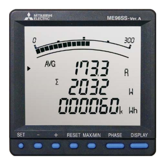
- Page 1 FACTORY AUTOMATION ELECTRONIC MULTI-MEASURING INSTRUMENT ME96SS...
- Page 2 ME96 Super-S Series ME96 Super-S Series Electronic Indicating Instruments Electronic Indicating Instruments functions and optional units functions and optional units Highly appreciated ME96SS Series Electronic Multi-Measuring Instruments measuring functions and network capability has been released. This new series has improved measuring accuracy; even the economy model MODBUS TCP communication unit for Ethernet communication and logging ®...
- Page 3 with enhanced measuring with enhanced measuring have been remodeled, and ME96 Super-S Series with enhanced has an active energy measuring accuracy corresponding to Class 0.5S. The unit for enhanced data backup can be added to the models. The new series and energy-saving measurement monitoring.
- Page 4 Outline and Features Improved Measurement Functions »Improved accuracy of active energy, reactive energy and power factor and expanded measurement ranges of harmonics and demand values have been realized. Model name Transmission/Option specifications Main measurement items MODBUS ® RTU communication A, DA, V, Hz = ±0.1% W, var, VA, PF = ±0.2% Plug-in module (options) ME96SSHA-MB...
- Page 5 Data in more than one logging unit can be managed with one SD memory card. Note: Use the SD memory card (EMU4-SD2GB) made by Mitsubishi Electric. Use of any memory card other than our product (EMU4-SD2GB) is not covered by the warranty.
- Page 6 ME96 Super-S Series Ver.A Features Succeeded Display Functions Large Bar Graph Display Special »Bar Graph Display Each measuring items can be displayed by a bar graph. With bar graph display, one can grasps the rated value and percentage against the alarm value instantly. (1) Bar Graph Fixed Display Alarm indicator Note: Alarm indicator blinks when it is set on alarm mode.
- Page 7 Impressive Monitoring Functions Advanced Alarm Display (1) A function to blink the backlight upon occurrence of an alarm is provided. On the conventional models, the display was lit up upon occurrence of an alarm. The new product has a setting function to blink the backlight upon occurrence of an alarm.
- Page 8 ME96 Super-S Series Ver.A Features Variety of Complementary Features Password Function With the password function, the following items can be protected from an accidental execution. Password-protected item Password-protected item Shift to the setting mode Adjust the time limit of rolling demand Reset the max./min.
- Page 9 Test Function »A test function is provided to check the wiring for communication, alarm output/contact output, analog output and pulse output without input of voltage or current. »At the time of wiring test before shipment of the board and counter test for system validation on site, test signals can be output only by applying the auxiliary power.
- Page 10 Specifications ‡ME96SSHA-MB Model name ME96SSHA-MB Three phase 4-wire, Three phase 3-wire (3CT, 2CT), Single phase 3-wire, Single phase 2-wire Phase wire (common use) Current 5AAC, 1AAC (common use) Three phase 4-wire: 277/480VAC (max) Three phase 3-wire: Delta connections: 220VAC (max), Star connections: 440VAC (max) Rating Voltage Single phase 3-wire: 220/440VAC (max)
- Page 11 ‡ME96SSRA-MB Model name ME96SSRA-MB Three phase 4-wire, Three phase 3-wire (3CT, 2CT), Single phase 3-wire, Single phase 2-wire Phase wire (common use) Current 5AAC, 1AAC (common use) Three phase 4-wire: 277/480VAC (max) Three phase 3-wire: Delta connections: 220VAC (max), Star connections: 440VAC (max) Rating Voltage Single phase 3-wire: 220/440VAC (max)
- Page 12 Specifications ‡ME96SSEA-MB Model name ME96SSEA-MB Three phase 4-wire, Three phase 3-wire (3CT, 2CT), Single phase 3-wire, Single phase 2-wire Phase wire (common use) Current 5AAC, 1AAC (common use) Three phase 4-wire: 277/480VAC (max) Three phase 3-wire: Delta connections: 220VAC (max), Star connections: 440VAC (max) Rating Voltage Single phase 3-wire: 220/440VAC (max)
- Page 13 ‡Standards Compliance Electromagnetic Compatibility Emissions EN61326-1/CISPR 11, Radiated Emission FCC Part15 Subpart B Class A EN61326-1/CISPR 11, Conducted Emission FCC Part15 Subpart B Class A Harmonics Measurement EN61000-3-2 Flicker Meter Measurement EN61000-3-3 Immunity Electrostatic discharge Immunity EN61326-1/EN61000-4-2 Radio Frequency Electromagnetic field Immunity EN61326-1/EN61000-4-3 Electrical Fast Transient/Burst Immunity EN61326-1/EN61000-4-4...
- Page 14 Optional accessory SD memory card (EMU4-SD2GB) *1: Use the SD memory card (EMU4-SD2GB) made by Mitsubishi Electric. Use of any memory card other than our product (EMU4-SD2GB) is not covered by the warranty. For more information on data, please refer to the following document.
- Page 15 Operating Instructions Functions ‡ Segment name Description »LCD Functions Lead Status Power factor status is lead Lag status Power factor status is lag Scale of the bar graph The scale of the bar graph Excessively low input On when the measurement value is lower than the minimum scale value Excessively high input On when the measurement value is higher than the maximum scale value Upper/lower limit alarm indicator...
- Page 16 Operating Instructions Basic Set-up Operations » To access setting mode, press and hold the buttons down at the same time RESET The underlined setting parameters are for 2s. Press the button to display the items to be set, and the buttons to set the initial value.
- Page 17 e(2) (2) In the case of using with VT eVT/Direct voltage <Secondary voltage settings> (a) Three phase 4-wire setting (phase voltage) 63.5V 100V 110V 115V 120V (b) Three phase 3-wire (2CT, 3CT) or Single phase 2-wire setting (line voltage) 100V 110V 220V DISPLAY...
- Page 18 Operating Instructions <Continued from previous page> eMODBUS ® eSet the MODBUS ® RTU communication parity. communication parity DISPLAY even (EVEn) rMODBUS ® rSet the MODBUS ® RTU communication stop bit. communication stop bit Stop bit 1 Stop bit 2 DISPLAY Set-up menu Select another set-up menu or end set-up.
- Page 19 Set-up menu 2: MODBUS TCP Communication settings (when ME-0000MT-SS96 is installed) ® * Only in the case of ME96SSHA-MB or ME96SSRA-MB, it is applicable. Set-up menu Adjust the set-up menu No. to “2”. DISPLAY qSelect MODBUS ® TCP communication or MODBUS ®...
- Page 20 Operating Instructions Set-up menu 3: Display settings (max. scale, active energy, harmonics, etc.) Set-up menu Adjust the set-up menu No. to “3”. q(1) qSet the maximum current scale value on the bar graph. (1)Maximum current scale value DISPLAY CT primary current value (special primary current value) Set-up menu 1.4.1 primary current setting...
- Page 21 uSelect with or without harmonic display. uHarmonic display (without) (with) When the display is set to “on,” the harmonic value measured will be displayed on an additional screen. Select another set-up menu or end set-up Set-up menu ‡To continue to set-up ‡To finish set-up Select the menu Press the...
- Page 22 Operating Instructions <Continued from previous page> eAnalog output CH2~4 eSet the output items for “analog output CH2~4.” output items The setting procedure is the same as that of qAnalog output CH1 output items . DISPLAY rSet the details for “analog output CH2~4.” The setting procedure is the same as that of wAnalog output CH1 detailed settings .
- Page 23 ‡Operation (for ME96SSHA-MB) »Display Change »Changing Phases Press , the measurement display switches over. Press , the current phase and the voltage phase switches over. PHASE DISPLAY When the buttons are held down for DISPLAY Example of changing phases (Three phase 4-wire system) 2 seconds or more, the display will change in reverse order.
- Page 24 Operating Instructions »Changing Upper/Lower Limits for Alarm Activation and Cancellation When measurement values exceed the upper/lower limit values that have been set, an alarm activates and the screen begins to blink. The blinking mark on the bar graph indicates the current upper/lower limit value settings. During Alarm Generation »...
- Page 25 ■Display Pattern Contents The items set in display patterns and additional settings will be displayed as explained in the following table. »ME96SSHA-MB Screen Display (Three phase 4-wire) Screen set based on display pattern Additional screens (set in set-up menu Nos. 3, 7 and 8) Display No.10 No.11 No.12 No.13 No.14 No.15 No.16 No.17 No.18 No.19...
- Page 26 Operating Instructions ■Display Pattern Contents The items set in display patterns and additional settings will be displayed as explained in the following table. »ME96SSRA-MB Screen Display (Three phase 4-wire) Screen set based on display pattern Additional screens (set in set-up menu Nos. 3, 7 and 8) Display No.10 No.11...
- Page 27 »ME96SSEA-MB Screen Display (Three phase 4-wire) Additional screens Screen set based on display pattern (set in set-up menu Nos.3 and 8) Display pattern No.8 No.9 No.10 No.11 No.12 No.13 (digital display) Harmonic No.1 No.2 No.3 No.4 No.5 No.6 No.7 Harmonic Harmonic Operating Operating...
- Page 28 External Dimensions/Installation/Connections Dimensions ME96SSHA-MB, ME96SSRA-MB Optional Plug-in Module : ME-4210-SS96, ME-0040C-SS96, ME-0052-SS96 91.6 88.8 81.2 25.2 17.1 46.8 Optional Plug-in Module : ME-0000BU-SS96 88.8 Terminal screw M3 81.2 95.8 25.2 91.6 ME96SSEA-MB 17.1 Optional Plug-in Module : ME-0000MT-SS96 88.8 81.2 25.2 Terminal screw M3 95.8...
- Page 29 Wiring 1 Applicable Cable Size Part Screw type Wire specifications Tightening torque The table on the right describes Product main body • Use of crimp-style terminals: the applicable wire size. (auxiliary power supply, AWG26 to 14 (2 wires can be connected.) voltage input, current input 0.6 to 0.8 N·m Applicable crimp-style terminal:...
- Page 30 External Dimensions/Installation/Connections Wiring Diagrams (Continued) Single phase 3-wire system Single phase 2-wire system: With VT T/R+ T/R+ MODBUS ® MODBUS ® T/R− T/R− Communication Communication qAuxiliary power supply: 100-240VAC or VDC MODBUS ® wFuse: 0.5A Communication eWhen the MODBUS ® RTU unit at the destination does not have an SG terminal, it is unnecessary to connect...
- Page 31 Wiring Diagrams (Continued) 1. Pulse output, alarm output, and contact input/output cables must not be in close proximity or bundled with power cables or high-voltage cables. When laid parallel, separate by the distance shown in the following table. Condition Distance Power lines under 600V/600A More than 30cm Other power lines...
- Page 32 Related Products ‡EcoWebServerIII Collection, storage, visualization, Mitsubishi Electric Energy-saving Data Collection Server publication on the web, analysis and monitoring From visualization to publication of energy data All can be realized by one server. Simple Set-up When using the set-up software supplied, power management meters connected to CC-Link and measurement data can be set by mouse and keyboard operations.
- Page 33 PC, etc. Forms and graphs can be easily prepared by using the spreadsheet software (logging unit utility*). * The logging unit utility can be downloaded for free from Mitsubishi Electric FA site. ‡EcoMonitorLight Energy measuring unit with integrated display for easily realizing the visualization of energy A two-model line-up: a Three phase 3-wire system designed for users wanting simple power measurements at low cost;...
- Page 34 Safety Precautions To ensure safety, read the following items carefully before use and always comply with procedures during use. Special attention should be given to items enclosed in a box and marked “Caution.” Additionally, please carefully read the operations manual supplied with the product before use, and ensure that the manual read by the end user as well.
- Page 35 Mitsubishi Electric shall not be liable for: Damage that cannot be attributed to Mitsubishi Electric; lost opportunity or earnings resulting from failure of a Mitsubishi Electric product; damage, secondary damage or compensation for an accident resulting from special circumstances regardless of whether or not the circumstances were foreseeable;...
- Page 36 Precautions Before Use • Please consult with a Mitsubishi Electric representative when considering the application of products presented in this catalogue with machinery or systems designed for specialized use such as nuclear power, electrical power, aerospace/outer space, medical, or passenger transportation vehicles.