
Related Manuals for Clarke CRT1


Summary of Contents for Clarke CRT1
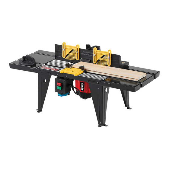
- Page 1 ROUTER TABLE MODEL NO: CRT1 PART NO: 6462115 OPERATION & MAINTENANCE INSTRUCTIONS ORIIGINAL INSTRUCTIONS GC1116...
-
Page 2: Specification
INTRODUCTION Thank you for purchasing this CLARKE Router Table designed for DIY use only and is ideal for use with a CLARKE CR1C router or other routers up to155mm dia base plate Before attempting to use this product, please read this manual thoroughly and follow the instructions carefully. -
Page 3: General Safety Rules
GENERAL SAFETY RULES WARNING: WHEN USING ELECTRIC POWER TOOLS, BASIC SAFETY PRECAUTIONS SHOULD ALWAYS BE FOLLOWED TO REDUCE THE RISK OF FIRE, ELECTRIC SHOCK AND PERSONAL INJURY INCLUDING THE FOLLOWING. READ ALL THESE INSTRUCTIONS BEFORE ATTEMPTING TO OPERATE THIS PRODUCT AND SAVE THESE INSTRUCTIONS FOR FUTURE REFERENCE. - Page 4 5. Before further use of the machine, it should be carefully checked to determine that it will operate properly and perform its intended function. Check for alignment of moving parts, binding of moving parts, breakage of parts, mounting or other condition that may affect its operation. 6.
-
Page 5: Electrical Connections
ELECTRICAL CONNECTIONS WARNING: READ THESE ELECTRICAL SAFETY INSTRUCTIONS THOROUGHLY BEFORE CONNECTING THE PRODUCT TO THE MAINS SUPPLY. Before switching the product on, make sure that the voltage of your electricity supply is the same as that indicated on the rating plate. This product is designed to operate on 230VAC 50Hz. -
Page 6: Product Inventory
Table pressure pad inc fittings Before assembling the table, ensure all components are present, any shortages etc should be reported to the Clarke dealer where the table was purchased. Parts & Service: 020 8988 7400 / E-mail: Parts@clarkeinternational.com or Service@clarkeinternational.com... - Page 7 ASSEMBLY 1. Lay the main table top (item 1) upside down on a flat surface as in Fig. 1. 2. Position one table top extension (item 02) as in Fig. 2. lace a table leg (Item 03) as shown in Fig. 3, loosely fix in position, using four screws and lock nuts;...
- Page 8 5. Once both table legs are loosely fitted, ensure the table and table extension are lying perfectly flat, and gently tighten all screws, working from the centre to the outside. Take care when tightening not to move the extension table. DO NOT overtighten. 6.
-
Page 9: Mounting The Router
11. Fit the fence feather boards as shown in Fig. 7 using the fixings supplied (hex head bolt x 4, washer x 4 and knob x 4. Pay attention to the feed direction. 12. Fit the table feather board as shown in Fig. - Page 10 3. Set the router in position on the underside of the table as central as possible, see Fig. 11. Insert two coach bolts into holes’C’ fig. 4 from the table top, which is now underneath. 4. Loosely secure the router in position with four clamps (Item 9).
-
Page 11: Operation
OPERATION When making adjustments etc, always ensure the router is isolated from the electrical supply by switching off and removing the plug from the socket. NOTE: Always refer to the specific router operating instruction manual when making height and speed adjustments etc. INSTALLING THE ROUTER CUTTER (BIT) To install bits whilst the router is in situ will require the router to be lowered fully. -
Page 12: Mitre Gauge
slide the jointing fence out towards the wood until it touches. Tighten the clamping Knob. Back the workpiece away from the cutter before switching on again and continuing machining. MITRE GAUGE To use the mitre gauge, the table feather board must be removed first. It may be necessary to loosen the front clamps holding the router in order to remove the bolts, not forgetting to retighten them before using the router again. -
Page 13: Dust Collection
and fingers safely away from cutting blades by using push sticks etc when working on small workpieces. DUST COLLECTION The router table is provided with a dust extraction facility, where a vacuum extractor may be connected to the outlet at the rear of the table, using the adapter supplied. -
Page 14: Height Adjustment
HEIGHT ADJUSTMENT In the case of routers too long to fit underneath the router table it is possible to overcome this problem by carrying out the following. NOTE: The following dimensions are the minimum sizes recommended, which can be increased if desired. Materials required: 1 x plywood baseboard 13mm (½”) x 400mm x 600mm. - Page 15 Centralise the router table feet on the baseboard as indicated in Fig C Once the table is carefully, centralised on the baseboard, ensuring the table doesn’t move, mark the four holes (X) to be drilled, using the table feet as a template Fig D.
- Page 16 Place one of the bearers onto the baseboard as centrally as possible over two of the holes Fig. E. Using ‘G’ clamps or similar, secure the bearer to the base board, taking care to ensure it doesn’t move. Turn the assembly over and drill the bearer through the holes in the baseboard using a 6mm drill.
-
Page 17: Parts Diagram
PARTS DIAGRAM Parts & Service: 020 8988 7400 / E-mail: Parts@clarkeinternational.com or Service@clarkeinternational.com... -
Page 18: Parts List
14 Coach Bolt 29 Fence Feather board(not shown) 15 Knob 30 Table feather board(not shown) When requesting spare parts, please quote the reference HT-CRT1 followed by the number listed. Parts & Service: 020 8988 7400 / E-mail: Parts@clarkeinternational.com or Service@clarkeinternational.com... -
Page 19: Declaration Of Conformity
DECLARATION OF CONFORMITY Parts & Service: 020 8988 7400 / E-mail: Parts@clarkeinternational.com or Service@clarkeinternational.com...
Need help?
Do you have a question about the CRT1 and is the answer not in the manual?
Questions and answers