Table of Contents
Advertisement
Advertisement
Table of Contents

Related Manuals for DRAKE TR-4C


Summary of Contents for DRAKE TR-4C
-
Page 2: Table Of Contents
TABLE OF CONTENTS Page CHAPTER I INTRODUCTION ..... . . l - l l - l . GENERAL DESCRIPTION ..... l - l l - 2 . - Page 3 TABLE OF CONTENTS (continued) Page 3-9. CW OPERATION......3-10. AM OPERATION ......3-11.
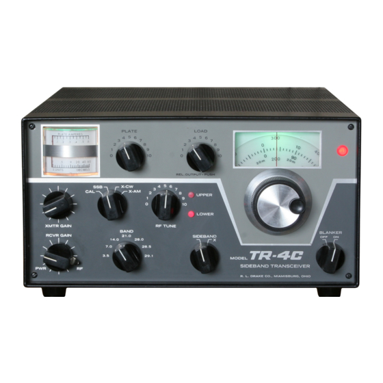
- Page 4 LIST OF ILLUSTRATlONS Figure Page l - l . TR-4C SIDEBAND TRANSCEIVER l - 2 2 - l . MICROPHONE CONNECTIONS 2 - l 2 - 2 . REAR CHASSIS CONNECTORS 2 - 2 2 - 3 . ELECTRICAL CONNECTIONS REQUIRED FOR MOBILE INSTALLATION 2 - 3 2 - 4 .
-
Page 5: Chapter I
GENERAL DESCRIPTION. Modification Kit. The TR-4C is a 300 Watt HF single sideband trans- 1 - 2 . M A N U A L C O V E R A G E . ceiver which covers the 80 through 10 meter amateur bands. -
Page 7: Specifications
SPECIFICATIONS GENERAL: Frequency Coverage 3.5 to 4.1 MHz, 7.0 to 7.6 MHz, 13.9 to 14.5 MHz, 21 .O to 21.6 MHz and 28.5 to 29.1 MHz; accessory crystals are available for the 28.0 to 28.6 MHz and 29.1 to 29.7 MHz segments of the 10 meter band. Mode of Operation: Lower Sideband, Upper Sideband, AM and CW. -
Page 8: Installation
Install a separate 2-2. LOCATION. speaker for use with the TR-4C. The R. L. Drake Model MC-4 Mobile Console is recommended for The location of the TR-4C is not critical. However, this type of installation. It includes a speaker and a... -
Page 9: Power Requirements
2-l 2. ACCESSORIES. Refer to figures 2-6 through 50/60 Hz, is required for stationary installations. 2-9 for the electrical connections required to The AC-4 is designed to fit inside the MS-4 operate the TR-4C with the various recommended accessories. speaker cabinet. NOTE... -
Page 15: Operation
100 kHz dial switch. In the X-CW position, the receiver portion 1 kHz dial .072 functions until the key is closed. The TR-4C then Operating frequency 7.272 MHz goes into the transmit mode, a CW sidetone is This dial may be calibrated over a short range by... -
Page 17: Front Panel Controls
FRONT PANEL CONTROLS S meter: Indicates relative level of received sig- VFO indicator lamp: Glows only when TR-4C nals. Indicates transmitter AGC when trans- VFO is operating. mitting. BLANKER switch: Provides on/off control for Plate meter: Indicates plate current in the final R. -
Page 18: Other Controls
DC Left Side (not illustrated). path to ground for receiving and an open cir- cuit for muting. All R. L. Drake receivers have RCVR/TCVR switch: Selects either the TR-4C this feature. Receiver or external receiver. -
Page 19: Tune Up
3-8. SSB OPERATION. matching network may be required. In the following discussion, it is assumed that the TR-4C has already been tuned up on the desired Preset the controls as follows: band as described in paragraph 3-7. Preset the Select the desired band with the BAND switch. -
Page 20: Cw Operation
3-10. AM OPERATION. clockwise. For AM operation, the Mode switch should be in On SSB, the TR-4C transmits on exactly the same the X-AM position and the SIDEBAND switch frequency on which it receives. Therefore, be sure should be in the X position. If a key is used, it that you have the signals tuned in so that the voices sound normal before you answer another station’s... -
Page 21: Novice Operation
If your linear amplifier has AGC output, connect plate reading of 0.115 Ampere. Turn MODE switch it to the TR-4C as shown in figure 2-7. If the to X-CW and set GAIN control for a plate current TR-4C is properly tuned, this should prevent flat of 0.1 15 Ampere. -
Page 22: Theory Of Operation
R. L. Drake AC-4, the cathode follower, V3A. On 15 meters, a 35.5 120 V AC power supply, or an R. L. Drake DC-4, MHz crystal is used with a 30.0-30.6 MHz coupler, V DC power supply. The TR-4C features a T2, and on the three meter ranges, 42.5, 43.0... -
Page 23: Transmitter Circuitry
T13 to the upper or lower crystal filter where the undesired sideband is The S meter in the TR-4C operates in a bridge filtered out. The resulting SSB signal is coupled circuit with the plates of a receiver IF amplifier,... - Page 24 product detector tube V16, through the SIDE- tor. Relay K2 shifts the 9 MHz oscillator to 9.001 TONE control, to provide audio output from the on transmit just as it does on X-CW. V and PTT functions are the same on AM as on SSB. speaker for CW monitoring.
-
Page 26: Maintenance
Disconnect the substitution. If this occurs, it is suggested that the Power Supply from the TR-4C before TR-4C be returned to the dealer or you may write removing covers. to the Customer Service Department at the address given in paragraph 5-l. Be sure to describe the 5-2. -
Page 27: Test Equipment
Connect the load from pin 9 of V3A and ground the tube a turn or two. and adjust T3 (bottom) for maximum S meter A d j u s t C45, located on top of the TR-4C reading. chassis. until the calibrator signal is zero beat Tune in a crystal calibrator signal at 2 1.300 MHz... - Page 28 All measurements were made with respect to ground with the power supply disconnected from the TR-4C. The BAND switch was on 7.0 MHz, the Mode switch was on CAL and the RCVR GAIN and XMTR GAIN controls were fully clockwise. The VOX, ANTI VOX and SIDETONE controls were fully clockwise and the ZERO control was set at the balance point.
-
Page 30: Receiver If
Table 5-2. Voltage Chart (continued) Transistor MEASURED AT: Emitter Base Collector Type Located in PTO 2N5950 2N3563 Located in PTO AT5059 2N3394 11.2 2N3877 NOTE: All measurements were made with an 11 Megohm VTVM and were taken from ground. RF TUNE, PLATE and LOAD controls were set as described in paragraph 3-7. -
Page 31: Filter Matching Transformer
With the SIDEBAND switch in USB, tune in the RF output indicator may be used. calibrator signal at 3.8 MHz for maximum S b. Tune up the TR-4C on 29.0 MHz for maximum meter reading. power output into a dummy load. - Page 32 Table 5-3. (Con tinued) FUNCTION Component Transmitter Receiver Type Power Amps. 6JB6 Matched V8, V9, IF Amplifier 6BZ6 v 1 2 12BA6 IF Amplifier 12AX7 v 1 4 AM Screen Modulator 13DE7 IF Amplifier 12BA6 6GX6 9 MHz Xtal Oscillator BFO/Product Detector v 1 7 6AQ5A...
Need help?
Do you have a question about the TR-4C and is the answer not in the manual?
Questions and answers