
Summary of Contents for HMF Scanreco G2
- Page 1 Scanreco G2 radio remote control system Scanreco G2, Radio remote control system 20-13 Rev.: HMF Technical Service Department...
-
Page 2: Table Of Contents
Contents Chapter Page INTRODUCTION .......................... 4 COMPONENT OVERVIEW, THE SCANRECO G2 RADIO REMOTE CONTROL SYSTEM ..4 GENERAL SYSTEM DESCRIPTION ................... 8 SET-UP GUIDES ......................... 9 PLUG AND SOCKET OUTLETS IN THE RADIO CONTROLLER ..........11 SURVEY OF TERMINALS IN THE RADIO CONTROLLER............12 THE SCANRECO G2 RADIO REMOTE CONTROL SYSTEM AND CGW 5355 ......13... - Page 3 Scanreco G2 radio remote control system PROGRAMMING OF ID-CODE ....................38 INDICATIONS, RADIO CONTROLLER ..................41 INDICATIONS, REMOTE CONTROL BOX .................42 THE QUALITY OF THE RADIO SIGNAL ..................43 FREQUENCY HOPPING ......................44 ONLINE PROGRAMMING ......................45 SELF-TEST MODE ........................46 FAULT MONITORING, ERROR INDICATIONS AND ERROR CODES ........47 TROUBLESHOOTING BY MEANS OF THE CGW 5355 ............49...
-
Page 4: Introduction
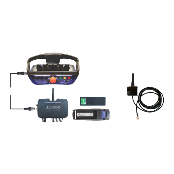
Scanreco G2 Instruction Manual. Component overview, the Scanreco G2 radio remote control system The Scanreco G2 radio remote control system is connected to the RCL 5300 controller and they communicate with each other in an integrated CAN bus system. - Page 5 Remote control box, MAXI or MINI The Scanreco G2 radio remote control system includes two versions of remote control boxes - MAXI or MINI. Their functionality is the same apart from the fact that the MINI version only has up to 6 linear control levers because of its size.
- Page 6 - The + and ÷ press buttons for adjusting the sound level of the buzzer. - The ↑/↓ press buttons for scrolling between the different screens. - The 1-4 press buttons for selecting specific screens. The screens are configured as described in the Scanreco G2 Instruction Manual. 20-13 Rev.:...
- Page 7 Scanreco G2 radio remote control system Radio controller The design of the radio controller: 1. Standard antenna (possibility for connecting external antenna) 2. Tumbler switch, Manual-OFF-Remote 3. M12 plug for remote control cable 4. LED status indication of the functional condition 5.
-
Page 8: General System Description
Scanreco G2 radio remote control system General system description The radio controller is connected to the RCL 5300 controller, which is the master controller in a CAN bus network where the radio remote control system and the safety system of the crane are communicating in an integrated system. -
Page 9: Set-Up Guides
Scanreco G2 radio remote control system Set-up guides Installation of the radio controller • To ensure optimal radio communication the radio controller must be fitted in as high a place as possible and with as much space around it as possible. If the antenna is surrounded by fixed objects, this will weaken the radio reception. - Page 10 Scanreco G2 radio remote control system • Penetrate the membranes of the cable lead-ins with for instance a small screwdriver. The fitting must be tight when pulling through the cable to ensure a tight system. • Fit a cable relief on the inside.
-
Page 11: Plug And Socket Outlets In The Radio Controller
Scanreco G2 radio remote control system Plug and socket outlets in the radio controller Each of the 6 plug and socket-outlets are dedicated to different crane and extra functions, CAN bus and power supply. In certain applications the outputs may be configured for alternative functions. -
Page 12: Survey Of Terminals In The Radio Controller
In the below table we have stated the number of the output terminals and output cables as well as the signal. Connection of output cables and the corresponding function can be found in the electric diagrams for the Scanreco G2 radio remote control system. Please note: In certain applications the output terminals may be configured for alternative functions. -
Page 13: The Scanreco G2 Radio Remote Control System And Cgw 5355
Scanreco G2 radio remote control system The Scanreco G2 radio remote control system and CGW 5355 In the service terminal CGW5355 a number of functions, used for setting-up, downloading, monitoring and reading of error log in relation to the G2 radio remote control system, have been implemented. -
Page 14: Description Of Scanreco G2 Parameters In The Cgw 5355
Menu item in CGW Description of functions and parameters 5355 1.1.1.1.1.25 The main function which is to be used when the PWM outputs in the Scanreco G2 PWM Mixer radio remote control system are to be set up. 1.1.1.1.1.25.1 It is possible to set up 14 digital signals from the K4 and K6 sockets. The K4... - Page 15 Scanreco G2 radio remote control system Menu item in CGW Description of functions and parameters 5355 1.1.1.1.1.25.2.5 Each PWM output can be controlled by an optional output signal - operated from the remote Source control box - in the Source menu. The output signal may be for a crane function, stabilizer function or extra function.
- Page 16 Scanreco G2 radio remote control system Menu item in CGW Description of functions and parameters 5355 1.1.1.1.1.25.2.7 Indicates the minimum current in % of PWM Max Current for a solenoid valve. The Min. Current value is individually adjustable for each single PWM output so that the manual control valve lever starts activation (flow from the port) when the remote control lever in case of activation has just passed the dead band.
-
Page 17: Setting Up Of Output Signals By Means Of The Cgw 5355
By means of the CGW 5355 it is possible to select signal sources which activate different output signals from the Scanreco G2 radio controller or controllers in the RCL 5300 Safety System. In the table below is indicated each single selectable signal name, the corresponding signal source and a description of the functionality controlled by the signal. - Page 18 Scanreco G2 radio remote control system Signal name Signal source Description of signal Activation of the ON push button on the High signal for the regeneration valve on the "jib REGEN JIB remote control box. - up" function (regeneration), when the load moment of the crane is less than 50 %.
- Page 19 Scanreco G2 radio remote control system Signal name Signal source Description of signal WINCH PARK Activation of the yellow push button High signal for changeover of a solenoid on the remote control box. valve in the hydraulic system for winch, so that the winch can be moved up into and down from stowing position.
- Page 20 Scanreco G2 radio remote control system Signal name Signal source Description of signal RC But 1 (RED) Activation of the red push button The signal gives the corresponding (pos. 8). functions as when pushing the red press button on the RCL 5300.
- Page 21 Scanreco G2 radio remote control system Signal name Signal source Description of signal RC But 16 (OPT 5) Activation of the ON push button. In the default settings the signal is used for starting up the remote control box. RC But 17 (OPT 6) Reserved No signal has been defined.
-
Page 22: Setting Up Control Valve Functions
Scanreco G2 radio remote control system Setting up control valve functions By means of the CGW 5355 it is possible to set up the control valve functions that are relevant to the crane configuration in question. In menu 1.1.1.1.2.7 - Valve function - ENT, 1.1.1.1.2.7.1 - Primary function - ENT you can select up to 15 crane functions - Valve 1-15. -
Page 23: Configuration Of Remote Control Levers
Scanreco G2 radio remote control system Configuration of remote control levers By means of the CGW 5355 it is possible to configure which remote control lever that has to activate the control valve functions. It is possible to set up 12 different configurations in menu 1.1.1.1.2.8.1 - Lever function - ENT: Lever setup 1-12. -
Page 24: Configuration Of Remote Control Levers, Operation Direction
Scanreco G2 radio remote control system Configuration of remote control levers, operation direction In the previous chapter, configuration of remote control levers by means of the CGW 5355 is described. In Lever setup (e.g. Lever setup 1 ENT Lever 1-8, menu 1.1.1.1.2.8.1.1.6-13) the... -
Page 25: Set-Up, Can Control Of The Crane Functions
Depending on the equipment there may be used other in- and output terminals in the RCL 5300. Please also see the chapter "Description of Scanreco G2 parameters in the CGW 5355" and "Setting up of output signals by means of the CGW 5355" as well as the electric diagram IRC,... - Page 26 Scanreco G2 radio remote control system Menu item in CGW 5355 Configuration Description of the function 1.1.1.1.3.11 - Display - Activate the feature - Display - if the remote control box has a display fitted. - Activate the feature PVED.
- Page 27 Scanreco G2 radio remote control system Menu item in CGW 5355 Configuration Description of the function 1.1.1.1.2.8 - Valve sensing - Configuration of remote control levers. 1.1.1.1.2.8.1 - Lever function - Configuration of the position of the control levers on the remote control box.
-
Page 28: Set-Up, Pwm Control Of The Crane Functions
Depending on the equipment, there may be used other output terminals in the radio controller. Please also see the chapter "Description of Scanreco G2 parameters in the CGW 5355" and "Setting up of output signals by means of the CGW 5355" as well as the electric diagram: NEMRC, G2. - Page 29 Scanreco G2 radio remote control system 1.1.1.1.1.25.2.6 - Source Setup ENT - Setting up the signal type for the individual output terminals for crane functions. SET, arrow down - Signal type for output terminal K1.1: A Prop 1.1.1.1.1.25.2.6.1 - K1.1 1.1.1.1.1.25.2.6.2 - K1.3...
-
Page 30: Set-Up And Connection Of Engine Control Functions
Scanreco G2 radio remote control system Set-up and connection of engine control functions In the table below is indicated an example of the standard set-up of the engine control functions. The engine control functions are activated by the tumbler switches 1, 2 and 3 on the remote control box. -
Page 31: Set-Up, Radio Remote Control Of Stabilizer Functions
Depending on the equipment there may be used other in- and output terminals in the radio controller. Please also see the chapter "Description of Scanreco G2 parameters in the CGW 5355" and "Setting up of output signals by means of the CGW 5355" as well as the electric diagram: Stabilizers by remote G2, 4+2 ways. - Page 32 Scanreco G2 radio remote control system 1.1.1.1.1.25.2.5.5 - 3A, K1.9 SET, arrow down - Left rear stabilizer leg "up/down" on output terminal K1.9: STB 6 1.1.1.1.1.25.2.5.6 - 3B, K1.11 SET, arrow down - Right rear stabilizer leg "up/down" on output terminal K1.11: STB 8...
- Page 33 Scanreco G2 radio remote control system 1.1.1.1.2.8.1.1.3 - Mode SET, arrow down - The configuration is activated in stabilizer mode: select Stb. 1.1.1.1.2.8.1.1.4 - Activation 1 SET, arrow down - The configuration lies directly on the remote control levers. select std.
-
Page 34: Set-Up And Connection Of Extra Digital Outputs
Scanreco G2 radio remote control system Set-up and connection of extra digital outputs In the table below is indicated an example of the standard set-up of extra digital functions (option) via the output terminals in the radio controller. The extra functions are operated by means of the tumbler switches nos. 4, 5 and 9 on the remote control box. -
Page 35: Set-Up And Connection Of Spotlight
Scanreco G2 radio remote control system Set-up and connection of spotlight In the table below is indicated an example of the standard set-up of a spotlight operated from the remote control box. The work light is operated by means of the green push button - hold for approx. 2 seconds - on the remote control box. -
Page 36: Download Of Icons And Texts
Scanreco G2 radio remote control system Download of icons and texts It is possible to download icons and text messages for the HMF InfoCentre by means of the CGW 5355 service terminal. During the procedure, the icons and texts are first downloaded to the radio controller and then to the remote control box. - Page 37 Scanreco G2 radio remote control system Monitoring of the radio remote control system by means of the CGW 5355 It is possible to monitor the output signals from the radio controller as well as feedback on spool travel etc. by means of the CGW 5355 service terminal.
-
Page 38: Retro-Fitting Of Hmf Infocentre
Scanreco G2 radio remote control system Retro-fitting of HMF InfoCentre It is possible to retro-fit an InfoCentre on a Scanreco G2 radio remote control system. EU radio remote control systems The MAXI and MINI remote control boxes are as standard fitted with a simplex radio transmitter meant for one-way communication. -
Page 39: Programming Of Id-Code
Scanreco G2 radio remote control system Programming of ID-code In order to establish a radio communication between the remote control box and the radio controller, the two units must be programmed with a unique ID-code. The ID-code is saved in the remote control box which ensures that it is not possible to transmit radio signals from another remote control box. - Page 40 Scanreco G2 radio remote control system Control of ID coding While the remote control cable is fitted, it is possible by means of the LED display of the radio controller to check whether the ID coding has been accepted. - If the LED display indicates "2 - ", the radio controller and the remote control box are not ID coded together.
-
Page 41: Indications, Radio Controller
Scanreco G2 radio remote control system Indications, radio controller Functional status is indicated two places on the radio controller: - Two external diodes Status and DV give a general indication (pos. 4). - The internal LED display gives more detailed information (pos. 5). -
Page 42: Indications, Remote Control Box
Scanreco G2 radio remote control system Indications, remote control box The remote control box has two diodes and a buzzer which indicate the functional status. Power LED Explanation Turned off The remote control box is deactivated Red lit The remote control box is activated and data are transmitted. -
Page 43: The Quality Of The Radio Signal
Scanreco G2 radio remote control system The quality of the radio signal The quality of the radio signal can be examined by means of indications from the external diodes of the radio controller and the internal LED display. Status LED display... -
Page 44: Frequency Hopping
Scanreco G2 radio remote control system Frequency hopping Contrary to radio remote control systems where it is possible to change manually between radio channels in case of externally induced radio interferences, the G2 radio remote control system has a built-in automatic frequency hopping technology. -
Page 45: Online Programming
RCL 5300 controller. On cranes with a Scanreco G2 radio remote control system fitted, which controls PWM electric modules but where no RCL 5300 controller is included, it is possible to carry out online programming directly from the remote control box. -
Page 46: Self-Test Mode
Scanreco G2 radio remote control system The LED display shows the value for the adjustment and the output terminal in question. Example: ”2A” - ”20” - 2A is the output terminal - 20 is the current intensity in percent. To get out of the online programming mode, push the red stop button. -
Page 47: Fault Monitoring, Error Indications And Error Codes
Fault monitoring, error indications and error codes The Scanreco G2 radio remote control system is working in an integrated network with the RCL 5300 controller. If failures occur in the radio remote control system, an error code will appear on the RCL 5300 display. - Page 48 Scanreco G2 radio remote control system Error indication, LED display All the outputs of the radio controller are monitored with regards to short circuit or overload. If the radio controller registers an error, it is indicated by the external red Status diode, which is flashing.
-
Page 49: Troubleshooting By Means Of The Cgw 5355
Scanreco G2 radio remote control system Troubleshooting by means of the CGW 5355 When the fault monitoring of the radio controller registers an error, and error codes are indicated as stated above, data with the error code are transmitted to the RCL 5300 controller, saving the error code in an error log in the black box. - Page 50 Scanreco G2 radio remote control system Error codes Comment LED display Error code in Error Cause Remedy display in G2 the RCL 5300 description black box 02.01 0201 Incorrect voltage Error in the DV Check the DV output, on the DV output.
- Page 51 Scanreco G2 radio remote control system Error codes Comment LED display Error code in Error Cause Remedy display in G2 RCL 5300 description black box 08.04 0804 CAN PDO - error The length of the The system carries out in message CAN data packet is automatic reset.
- Page 52 Scanreco G2 radio remote control system Error codes Comment LED display Error code in Error Cause Remedy display in G2 the RCL description 5300 black 17.01 1701 The power The power supply is The system carries out supply is too low.
-
Page 53: Error Indication, Remote Control Box
Lever no. 8* is not in neutral position. *Please see the chapter: "Configuration of remote control levers, operation direction". As regards radio remote control systems with HMF InfoCentre that have a two-way transmission system (Duplex), the Micro LED is used for indicating the radio quality on the signal from the radio controller and back to the remote control box. -
Page 54: Outlets
Scanreco G2 radio remote control system Remote control cable, cable connections and plug and socket-outlets It is possible to remote control the crane by fitting a 10 m remote control cable between the radio controller and the remote control box. -
Page 55: Marking And Identification
All radio controllers and remote control boxes are marked by a label, stating the part number and the serial number of the components in question. When contacting HMF concerning support or in case of warranty claims, please always state the part number of the component.
Need help?
Do you have a question about the Scanreco G2 and is the answer not in the manual?
Questions and answers