
Related Manuals for ABB UCC Series


Summary of Contents for ABB UCC Series
- Page 1 On-load tap-changers, types UCC and UCD with motor-drive mechanism, type BUE Installation and Commissioning Guide...
- Page 2 This document must not be copied without our written permission, and the contents thereof must not be imparted to a third party nor be used for any unauthorized purpose. Contravention will be prosecuted.
- Page 3 Recommended Practices WARNING, CAUTION and NOTE WARNING A WARNING provides information which, if disregarded, could cause injury or death. CAUTION NOTE: Safety Precautions WARNING Unused transformer oil is slightly harmful. Fumes from unused warm oil may irritate the respiratory organs and the eyes. After long and repeated contact with transformer oil skin becomes very dry.
- Page 4 Waste and cleaning up: Should be absorbed by an absorber. Treat it as hazardous to the environment. Upon fire: The fire should be extinguished by using powder, foam or carbon acid. WARNING Be aware of the risk for slipperiness caused by oil spillage for instance when working on the transformer cover.
- Page 5 CAUTION CAUTION CAUTION Mounting of Gaskets CAUTION During Oil Filling WARNING When oil that has been used in a diverter switch housing is pumped out, conducting tubes and hoses that are earthed should be used to avoid the risk of explosion due to the gases produced by the arcs during service.
- Page 6 After Oil Filling CAUTION NOTE: During Service WARNING Small amounts of explosive gases will always come out from the breathing devices (dehydrating breather or one-way breather). Make sure that no open fire, hot surfaces or sparks occur in the immediate surroundings of the breathing devices. WARNING If a failure in power supply occurs during operation, the operation will be completed when the power returns.
-
Page 7: Table Of Contents
Contents Introduction ____________________________________________ Type Designation ________________________________________ Required Tools __________________________________________ Required Material _______________________________________ Oil ___________________________________________________ Oil Conservator _________________________________________ Oil Filter Unit for Continuous Oil Filtration ___________________ Weights _______________________________________________ Tightening Torque _______________________________________ Receiving ______________________________________________ Unpacking _____________________________________________ Inspection on Receipt _____________________________________ Temporary Storage before Assembly _________________________ Installation in the Transformer ______________________________ Cover-Mounting _________________________________________ 3.1.1... - Page 8 Oil Filling ______________________________________________ Filling Methods and Restrictions ____________________________ Before Filling ___________________________________________ Filling at Atmospheric Pressure _____________________________ Filling under Vacuum ____________________________________ 6.4.1 Oil Conservator Filled Afterwards ___________________________ 6.4.2 Oil Conservator Filled under Vacuum ________________________ Restoring the Gas Cushion _________________________________ 6.5.1 Procedure ______________________________________________ Electrical Connection and Testing ___________________________ General ________________________________________________ Connecting and Testing the Motor-Drive Mechanism and the...
-
Page 9: Introduction
1 Introduction 1 Introduction The arrangement of on-load tap-changers types UCC and UCD are shown in Figs. 1 and 2. A UCC on-load tap-changer has always tap selector IV. A UCD on-load tap- changer has tap selector III or G. To make transportation easy the on-load tap-changer is delivered in three main parts. -
Page 10: Type Designation
1 Introduction 1.1 Type Designation U C C . . XXXX/YYYY/IV U C D . . XXXX/YYYY/III Example: UCDRE 650/1000/III Type of switching Linear R Plus/Minus D Coarse/Fine Type of connection N Three-phase star point (one unit) Single-phase (one unit) Impulse withstand voltage to earth Maximum rated through-current Tap selector size... - Page 11 1 Introduction Serial No. Diverter switch housing Shielding ring (not in combination with tap selector size G) Serial No. in the bottom of the diverter switch (see Fig. 29) Serial No. Serial No. Serial No. Tap selector size IV Tap selector size III Tap selector size G...
- Page 12 1 Introduction Horizontal drive shafts Bevel gear and protective tubes Bevel gear Pressure relay Vertical drive shafts and protective tubes Shielding rings and caps, Rating plate only for UCC, UCD with Hand crank impulse withstand voltage (inside the to earth exceeding 380 kV cover) Motor-drive mechanism...
-
Page 13: Required Tools
Lifting bar. Article No. LL 133 016-D 3.2.2 n Special hand crank for operating the on-load tap-changer on the bevel gear (can be ordered from ABB, under ”further requirements” on the ordering data sheet. Art. No. LL117 016-M). n Hack saw (only for installation) -
Page 14: Oil
Filling, in this guide. 1.5 Oil Conservator The on-load tap-changer has to be connected to an oil conservator. ABB recommends to use a separate conservator for the on-load tap-changers with both oil and air side separated from the main conservator of the transformer. -
Page 15: Oil Filter Unit For Continuous Oil Filtration
If the on-load tap-changer should have an oil filter unit for continuous oil filtration from ABB, installation and commissioning instructions are found in the manual for the oil filter unit, ”Oil filter unit for On-Load Tap-Changers, Manual” delivered with the oil filter unit. - Page 16 1 Introduction On-load tap-changer Approx. weight in kg Type designation Tap-changer Required Total without oil UCC.N.../.../IV 380/800, 1200 1050 1750 380/1600 1140 1840 650/800, 1200 1090 1850 650/1600 1180 1940 1050/800, 1200 1110 1970 1050/1600 1200 2060 UCC.E.../.../IV 380/3600 1040 1740 380/4200 1130...
-
Page 17: Tightening Torque
It is also recommended that photographs are taken of the damaged details. Mark the photos with ABB’s reference number and the serial number of the on-load tap-changer and send them to ABB for comments. -
Page 18: Installation In The Transformer
3 Installation in the Transformer 3 Installation in the Transformer The cover-mounting method or yoke-mounting method is used. WARNING The intermediate gear and the insulating shaft of the diverter switch housing moves during operation. Keep away during operation to avoid injuries! The diverter switch housing and the tap selector are designed to be lifted in the lifting eyes, see Fig. -
Page 19: Cover-Mounting
3 Installation in the Transformer 3.1 Cover-Mounting (For Yoke-Mounting, see section 3.2). The diverter switch housing and tap selector are delivered packed separately. 3.1.1 UCC with Tap Selector size IV 1. Unpack the diverter switch housing and the tap selector. Remove the drying agents and the yellow cushions with vapour phase inhibitor for protection against corrosion in the tap selector and on the diverter switch housing. - Page 20 3 Installation in the Transformer 4. Lift the diverter switch housing in the lifting eyes as shown in Fig. 3 and lower it carefully through the opening in the transformer top cover, see Fig. 4. Place the diverter switch housing correctly in position for mounting the outer shaft system (see transformer drawing).
- Page 21 3 Installation in the Transformer Screw (to be removed) Transport locking (to be removed) Lifting eyes with fasteners (to be removed) TC_00191 9. Lift the diverter switch housing in position and fit the tap selector to the diverter switch housing, see Fig. 4. The tap selector driving pin shall fit into the large gear wheel slot, see Fig.
- Page 22 3 Installation in the Transformer Shielding ring (not to be dismantled) Nut M10 Insulating shaft Socket Upper shielding ring. (To be dismantled) screw M10x30 Diverter switch housing X-contacts V-contacts TC_00278 Lower shielding ring. (To be dismantled) Upper shielding ring of Shielding cap the tap selector Conductor...
-
Page 23: Ucd With Tap Selector Size
3 Installation in the Transformer 3.1.2 UCD with Tap Selector size III 1. Unpack the diverter switch housing and the tap selector. Remove the drying agents and the yellow cushions with vapour phase inhibitor for protection against corrosion in the tap selector and on the diverter switch housing. 2. - Page 24 3 Installation in the Transformer 8. Remove the transport locking and the lifting eyes with fasteners from the top section of the tap selector, see Fig. 8. CAUTION Lifting eyes with fasteners (to be removed) Transport locking (to be removed) Screw (to be removed) TC_00216 9.
- Page 25 3 Installation in the Transformer Shielding ring (not to be dismantled) Diverter switch housing Upper shielding ring (To be dismantled) V-contacts Shielding cap X-contacts Lower shielding ring (To be dismantled) Conductor Tap selector Support Plain washer 14x30x2.5 Spring washer Plain washer TC_00095 13x34x3 Fig.
-
Page 26: Ucd With Tap Selector Size G
3 Installation in the Transformer 3.1.3 UCD with Tap Selector size G 1. Unpack the diverter switch housing and the tap selector. Remove the drying agents and the yellow cushions with vapour phase inhibitor for protection against corrosion in the tap selector and on the diverter switch housing. 2. - Page 27 3 Installation in the Transformer 8. Lift the diverter switch housing in position and fit the tap selector to the diverter switch housing, see Fig. 4. The tap selector driving pin shall fit into the large gear wheel slot, see Fig. 17, A-A. CAUTION 9.
- Page 28 3 Installation in the Transformer Locking device Remove screws Shaft Potential Switch TC_00172 c. Dismount the screw and the washers in the bottom of the tap selector, see Fig. 13. Tap Selector Potential Slot connection Dismount the screw Potential Switch Washer TC_00173...
- Page 29 3 Installation in the Transformer d. Lift the tie-in resistor unit against the tap selector and connect the potential connection with the removed screw and washers, see Figs. 14 and 15. e. The pin in the tap selector shaft must be in position to fit in the slot of the potential switch shaft.The lip in the potential switch cylinder shall fit in the cut of the tap selector, see Fig.
- Page 30 3 Installation in the Transformer f. Lift the tie-in resistor switch. Check that the potential connection do not disturb the function of the potential switch and the tap selector. Turn the tie-in resistor cylinder counter clock-wise so the brackets of the potential switch enter the center supports of the tap selector, see Fig.
- Page 31 3 Installation in the Transformer Shielding ring (not to be dismantled) Shielding cap Shielding ring (to Diverter switch be dismantled) housing Conductor V-contacts X-contacts Cleat Plain washer Insulating screws 13x34x3 M16x130 Spring washer and nuts Socket screw M12 x 50 (6x) Fig.
- Page 32 3 Installation in the Transformer 12. Connect the supplied conductors between the diverter switch housing and tap selector, see Fig. 17. The conductor ends and their connecting points have the same markings. Fasten the conductors with cleats, see Fig. 17, A-A. The number of conductors is varying depending on the rated through current and the type of connection.
-
Page 33: Yoke-Mounting
3 Installation in the Transformer 3.2 Yoke-Mounting (Pre-mounting on active part of the transformer). (For Cover-Mounting, see section 3.1). The top section of the diverter switch housing is designed to be divided into an upper and a lower flange, see Figs. 21 and 23, to fit the yoke-mounting. Gear unit Transformer active part On-load tap-changer... -
Page 34: Mounting When The Transformer Ratio Measurement Is Carried Out Before Drying
3 Installation in the Transformer 3.2.1 Mounting when the Transformer Ratio Measurement is carried out before Drying 1. Assemble the diverter switch housing and the tap selector as follows: UCC with tap selector IV, see section 3.1.1, steps 1, 6-13 UCD with tap selector III, see section 3.1.2, steps 1, 6-13 UCD with tap selector G, see section 3.1.3, steps 1, 6-13 2. - Page 35 3 Installation in the Transformer Cover Clamp O-ring Lifting eye for the diverter switch O-ring Oil draining plug Upper flange Locking device DS 4 Screw O-ring Lower flange Yoke fork TC_00205 Oil draining plug Socket handle Bottom valve key DS16, key-width 10 mm Oil draining tube...
-
Page 36: Mounting When The Transformer Ratio Measurement Is Carried Out After Drying
3 Installation in the Transformer 9. Loosening the screws for the four clamps that keep the bevel gear and remove the bevel gear. Take care of O-ring, clamps and fasteners. Store the bevel gear in a dust-free place. CAUTION 10. Mount the locking device DS 4 on the driving shaft of the on-load tap-changer, see Fig. -
Page 37: Mounting On Transformer Cover
3 Installation in the Transformer Lifting equipment Yoke fork On-load tap-changer TC_00122 3.2.3 Mounting on Transformer Cover (After drying process.) 1. After the transformer cover is mounted, place the gasket in the flange for the on- load tap-changer. (This gasket is not included in the on-load tap-changer delivery). - Page 38 3 Installation in the Transformer 4. Place the upper flange over the opening in the transformer cover. Turn the upper flange so the flange for the bevel gear is aligned with the driving shaft. The screws in the lower flange shall fit into the holes in the upper flange, see Fig. 28. 5.
- Page 39 3 Installation in the Transformer CAUTION 8. Insert thirty M16 studs through holes in the upper flange, down into threaded holes in the flange of the transformer cover. If the studs do not fit, the position of the on-load tap-changer must be adjusted, which may require lifting. After mounting the studs, remove the lifting tool and tighten the nuts.
-
Page 40: Connection To Terminals
3 Installation in the Transformer 3.3 Connection to Terminals Connection to the tap selector should follow the connection diagram supplied with the on-load tap-changer. In order to obtain maximum reliability of the tap selector contacts, the temperature rise of the conductors connected to the tap selector should be kept as low as possible and should in no case exceed 30K above the surrounding oil. - Page 41 3 Installation in the Transformer Tap selector Terminal Expansion bend Faulty Correct TC_00130 NOTE: Lower flange Yoke fork beam TC_00132 Inserts CAUTION...
-
Page 42: Transformer Ratio Measurement
If it is carried out before drying, no drive system is mounted. The on-load tap- changer has thus to be operated directly on the shaft coupling of the bevel gear on the upper flange. A special hand crank can be ordered from ABB, see section ”1.2 Required Tools” in this guide. -
Page 43: Transformer Ratio Measurement Before Drying
3 Installation in the Transformer 3.4.1 Transformer Ratio Measurement before Drying 1. Remove the locking device from the gear unit on the upper flange, see Fig. 22. Keep the locking device for remounting after transformer ratio measurement. Also remove the cover of the bevel gear to get access to the position indicator. Keep all fasteners and the gasket for remounting. -
Page 44: Drying
4 Drying 4 Drying The on-load tap-changer is dried together with the transformer using one of the following processes: alternating hot-air and vacuum or vapour-phase at a temperature of max. 135 °C (275 °F). 4.1 Observations before Processing 1. If not earlier done, lift the diverter switch out from the housing, see section 3.2.1 steps 5 and 7. -
Page 45: Installation Of Diverter Switch
4 Drying 3. If a tie-in resistor from ABB is supplied, its screw joints are to be retightened (tightening torque 15 Nm) and locked by the method specified by the transformer manufacturer for similar screw joints. 4. If the tap selector has supporting plates these should also be retightened and locked by method specified by the transformer manufacturer for similar screw joints. - Page 46 4 Drying Lifting eye Lifting device Springs Shielding-ring (not on 380 kV) Plug-in contacts Guiding slots TC_00128 Tie-rod Guiding pins Driving pin Plug-in contacts Serial number...
- Page 47 4 Drying Holes for guiding pins Notch for the driving pin Coupling disc Guiding bars TC_00123 Lifting device (upper part) of the diverter switch Min. 1 mm Upper flange TC_00068...
- Page 48 4 Drying Top cover Hexagon bolt M12x40 (30x) plain washer 13x24x2,5 O-ring Transformer cover Yoke fork beam (when yoke- mounted) TC_00062 Top cover TC_00132...
-
Page 49: Final Assembly
5 Final Assembly 5 Final Assembly 5.1 Mounting of the Motor-Drive Mechanism See Fig. 39. Proceed as follows: 1. Mount the motor-drive mechanism onto the transformer. The mounting holes on the transformer should be leveled within 1 mm. If adjustment is needed, shims should be used. - Page 50 5 Final Assembly Exact position TC_00261 Tolerances Transformer The same indicated tap position Position indicator TC_00141 TC_00203 Brake disc Adjustment nuts Red mark Brake assembly...
-
Page 51: Mounting Of External Drive Shafts
5 Final Assembly 5.2 Mounting of External Drive Shafts The external drive shafts consists of square tubes and shall be connected to the spherical shaft ends on bevel gears and motor-drive mechanism by means of two coupling halves. The square shafts and protective tubes must be cut before mounting. CAUTION Apply a thin layer of grease, GULF-718EP Synthetic grease or Mobilgrease 28 or SHELL-Aero Shell Grease 22 to all spherical shaft ends and unpainted surfaces of the... - Page 52 5 Final Assembly SA11 SA11 Bevel gear on the SA12 SA12 Diverter switch housing SA10 SA13 SA25 SA22 SA24 SA23 SA25 SA13 SA10 SA21 SA20 SA17 SA18 SA19 Horizontal drive shaft SA10 SA11 SA12 SA13 SA10 Hose clip SA11 Couplinghalves SA16 SA12 Hexhead cap screw M6 Vertical drive shaft...
-
Page 53: Mounting Of Vertical Drive Shaft
5 Final Assembly 5.2.1 Mounting of Vertical Drive Shaft 1. Mount the bevel gear SA21 on the transformer, with O-ring SA20, four clamps SA17, hexagon head bolts M10, SA18 and washers SA19, see Fig. 40. 2. Determine the dimension K2 between the spherical shaft ends, see Fig. 41a. 3. - Page 54 5 Final Assembly SA21 SA10 SA11 SA16 SA10 SA16 SA15 SA15 SA10 SA14 SA14 TC_00147 Driving pin SA15 SA10 TC_00148 TC_00149 Square shaft Square shaft SA11 SA13 SA11 SA12 TC_00147 TC_00170...
-
Page 55: Mounting Of Horizontal Drive Shaft
5 Final Assembly 5.2.2 Mounting of Horizontal Drive Shaft 1. Determine the dimension K1 between the spherical shaft ends, see Fig. 42a. SA 21 Locking device TC_00148 2. Cut the horizontal square shaft SA22 to dimension = K1 minus 6 mm. Remove the burrs. - Page 56 5 Final Assembly SA21 SA11 TC_00148 6. Connect the square shaft with the mounted coupling halves to the shaft of the bevel gear SA21, see Fig. 42c. Mount two coupling halves SA11 to the other end of the square shaft and to the shaft of the bevel gear on the on-load tap-changer. Push the shaft to the bottom of the fitting in the coupling halves.
-
Page 57: Before Operation
5 Final Assembly SA10 SA24 SA25 SA23 SA10 Slot facing downwards TC_00148 SA23 8. Push the two protective tubes on to the bevel gears and clamp them with hose clips, SA10, see Fig. 42e. NOTE: Apply the self-adhesive information plates SA25 around the tubes on about the middle of the tube length. -
Page 58: Pressure Relay
5 Final Assembly 5.3 Pressure Relay 5.3.1 General The diverter switch housing of the on-load tap-changer is supplied with a pressure relay. In the event of overpressure in the diverter switch housing, and if correctly connected, the relay trips the transformer main circuit breakers. It is also recommended to connect the pressure relay in the trip circuit of the power supply during testing of the transformer. -
Page 59: Checking At Commissioning Of The Transformer
5 Final Assembly 5.3.3 Checking at Commissioning of the Transformer Information plate Valve handle Test tap (R 1/8”) TC_00264 1. Set the valve handle in the test position as shown on the information plate. 2. Connect the air pump and the pressure gauge to the test tap on the pressure relay. 3. -
Page 60: Connection To The Oil Conservator
Remove the transport cover on the flange for connection to the oil conservator. Make sure the O-ring is in place on the flange and connect the pipe to the oil conservator. Tighten the nuts. CAUTION Oil filter with housing can be ordered from ABB. -
Page 61: Oil Filling
6 Oil Filling 6 Oil Filling 6.1 Filling Methods and Restrictions Oil filling can be carried out at atmospheric pressure or under vacuum. The wall between the diverter switch housing and the transformer tank is designed to withstand vacuum on one side and atmospheric pressure on the other side. It is not allowed to have vacuum on one side and the pressure of a high oil column on the other side. -
Page 62: Filling At Atmospheric Pressure
6 Oil Filling 6.3 Filling at Atmospheric Pressure 1. Open the conservator valve, if any. 2. Dismantle the breathing device on the conservator for the on-load tap-changer. 3. Pump oil into the diverter switch housing via the oil valve (connection dimensions, see the dimension drawing for the on-load tap-changer). -
Page 63: Oil Conservator Filled Afterwards
6 Oil Filling 6.4.1 Oil Conservator Filled Afterwards If an oil filter is mounted on the flange for the oil conservator (only on transformers with a common oil conservator for both the transformer and the on-load tap-changer), it should be removed. Establish a connection between the transformer and the diverter switch housing, for instance by putting oil valves on the flange for the conservator and the flange for the gas operated relay respectively and connect a tube between the valves, see... -
Page 64: Restoring The Gas Cushion
The procedure below is used for on-load tap-changers without oil filter unit for continuous oil filtration. In case the on-load tap-changer is equipped with an oil filter unit for continuous oil filtration from ABB, and it is installed according to our recommendations, follow the instructions in ”Oil filter unit for on-load tap-changers, manual”... -
Page 65: Procedure
6 Oil Filling 6.5.1 Procedure 1. Close the valve in the tube to the conservator. 2. Connect the oil pump to the oil valve. (For connection dimensions, see the dimension drawing for the on-load tap-changer), see Figs. 45 and 47. 3. -
Page 66: Electrical Connection And Testing
7 Electrical Connection and Testing 7 Electrical Connection and Testing 7.1 General Before the transformer is energized, tests have to be carried out to make sure that all mechanical and electrical connections are correct, and to check the proper functioning of the motor-drive mechanism and the on-load tap-changer. -
Page 67: Electrical Tests On Transformer
7 Electrical Connection and Testing Operate the driving mechanism electrically between the end positions. Check the end stops. When trying to operate it electrically beyond the end position, the motor should not get started. Check the mechanical end stop by trying to hand crank it beyond the end position. -
Page 68: Transport
8 Transport 8 Transport 8.1 Dismantling before Transport The on-load tap-changer is usually transported without accessories (pressure relay, motor-drive mechanism, bevel gear and drive shafts) to prevent damage to them. To make sure that everything is set up properly on site with a minimum of work, it is important to put the on-load tap-changer in the position and operated from the position given in the single-phase diagram delivered with the unit and fit locking devices properly during dismantling in the transformer factory. -
Page 69: Oil Level During Transport
8 Transport CAUTION 8.2 Oil Level During Transport The following adjustments of the oil level should be carried out when the on-load tap- changer should be transported. CAUTION 8.2.1 Transformer filled with Oil The transformer is transported filled with oil. When the transformer is transported filled with oil the on-load tap-changer should also be transported filled with oil. -
Page 70: Conservator Mounted
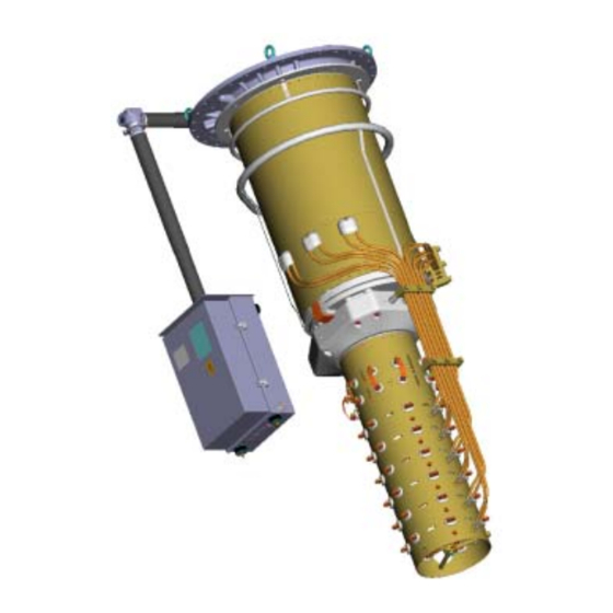
9 Commissioning 8.2.2.1 Conservator mounted Drain the oil from the diverter switch housing by means of a pump connected to the oil valve. Let the on-load tap-changer be in contact with the ambient air through the breathing device on the conservator. 8.2.2.2 Conservator dismounted Drain the oil from the diverter switch housing by means of a pump connected to the oil valve. - Page 71 9 Commissioning Oil valve Pressure relay Horizontal drive shaft and protective tubes Bevel gear Vertical drive shaft and protective tubes Motor-drive mechanism TC_00139 Fig. 48 shows the arrangement of the on-load tap-changer, motor-drive mechanism and drive-shafts. The pressure relay is usually delivered in a separate package and installed at commissioning.
-
Page 72: Connection To The Oil Conservator
9 Commissioning 9.1 Connection to the Oil Conservator Follow appropriate parts of the instructions in section 5.5. Connect the cables to the low level alarm contact on the oil level indicator. 9.2 Mounting the Motor-Drive Mechanism and Drive Shafts The motor-drive mechanism and drive-shaft system should have been assembled and disassembled in the transformer factory according to the transport sections in this guide. -
Page 73: Mounting Of The External Drive Shafts
9 Commissioning 9.2.3 Mounting of the External Drive Shafts The external drive shafts consists of square tubes and shall be connected to the spherical shaft ends on bevel gears and motor-drive mechanism by means of two coupling halves. CAUTION Apply a thin layer of grease, GULF-718EP Synthetic grease or Mobilgrease 28 or SHELL-Aero Shell Grease 22 to all spherical shaft ends and unpainted surfaces of the bevel gears. - Page 74 9 Commissioning SA18, SA19 SA17 SA21 SA20 Driving pin SA11 SA10 SA16 SA10 SA16 SA15 SA15 Motor-Drive SA10 Mechanism SA14 TC_00156 TC_00147 SA18, SA19 SA15 SA17 SA10 TC_00156 TC_00149 Fixing flange of the bevel gear...
-
Page 75: Mounting Of The Horizontal Drive Shaft
9 Commissioning 9.2.5 Mounting of the Horizontal Drive Shaft 1. Dismantle the locking device from the bevel gear on the diverter switch housing. Locking device SA14 SA24 SA10 SA23 SA11 TC_00148 TC_00148 2. Put the square shaft, protective tubes and hose clips according to Fig. 50b. SA11 SA21 SA11... - Page 76 9 Commissioning Max. 3 mm M8 screw Coupling Driving pin Driving pin TC_00150 TC_00148 TC_00170 NOTE: CAUTION Fit the screws to the holes that are aligned with the holes in the disc of the bevel gear on the on-load tap-changer. The disc might be turned a few degrees if needed for aligning the holes.
-
Page 77: Before Operation
9 Commissioning 9.2.6 Before Operation 1. Check again that the on-load tap-changer and the motor-drive mechanism are in the same operating position, see section 5.1. 2. Remove the locking device of the motor-drive mechanism, see Fig. 51. NOTE: Locking device TC_00151 9.3 Pressure Relay Follow appropriate parts of section 5.3. -
Page 78: Electrical Connection And Testing
9 Commissioning 9.6 Electrical Connection and Testing Make all wiring work and make the appropriate tests according to chapter 7. Remove the drying agent inside the cabinet of the motor-drive mechanism. 9.6.1 Motor Protection The function of the protective motor switch is checked. For three-phase AC motors, one of the phase fuses is removed and the function time of the protective motor switch is checked by a RAISE or LOWER operation. -
Page 79: Position Transmitter And Other Position Switches
9 Commissioning 9.6.4 Position Transmitter and other Position Switches Check the function of the position transmitter and other position switches. 9.6.5 Light Check that the light is switched on when the door is opened and goes out when the door is closed. 9.6.6 Heater Switch off all power supplies and feel with a finger that the heater has been warmed up during earlier tests. - Page 80 ABB Power Technology Products AB Components Visiting address: Postal address:...