
Related Manuals for Festo CPX-P-8DE-N Series


Summary of Contents for Festo CPX-P-8DE-N Series
- Page 1 CPX terminal (-P) Description Electronics CPX-P modules and CPX-P connection blocks Input modules – CPX-P-8DE-N-… In-line valve manifolds – CPX-P-AB-4XM12.. – CPX-P-AB-2XKL.. Description 575 379 en 1209NH [758 826]...
- Page 3 ....... . . 575 379 © (Festo AG & Co., D-73726 Esslingen, 2012) Internet: http://www.festo.com E-Mail: service_international@festo.com...
- Page 4 Contents and general instructions DeviceNet®, Modbus®, PROFIBUS®, PROFINET® SPEEDCON® and Torx® are registered trademarks of the respective trademark owners in certain countries. Festo P.BE-CPX-P-EA-EN en 1209NH English...
-
Page 5: Table Of Contents
........Functions of the input module CPX-P-8DE-N......Festo P.BE-CPX-P-EA-EN en 1209NH English... - Page 6 ............Festo P.BE-CPX-P-EA-EN en 1209NH English...
-
Page 7: Important User Instructions
... means that failure to observe this instruction may result in material damage. In addition, the following pictogram marks passages in the text which describe activities with electrostatically sensitive devices: Electrostatically sensitive devices: Incorrect handling may cause damage to devices. Festo P.BE-CPX-P-EA-EN en 1209NH English... - Page 8 Recommendations, tips and references to other information sources. Accessories: Specifications on necessary or useful accessories for the Festo product. Environment: Information on the environmentally friendly use of Festo products. Text designations Bullet points denote activities that may be carried out in • any sequence.
-
Page 9: General Safety Information
Discharge yourself from static discharges before assem- • bling or disassembling modules to protect the modules. Observe the regulations for the electrical supply of CPX ter- minals in the CPX system description (Protective Extra-Low Voltage, PELV). Festo P.BE-CPX-P-EA-EN en 1209NH English... -
Page 10: Intended Use
Contents and general instructions Intended use The CPX-P modules documented in this description have been designed exclusively for use in P variant CPX terminals from Festo. The CPX-P modules should only be used as fol- lows: – as intended –... - Page 11 Not all of the available connection blocks are permitted for variant P CPX terminals. When configuring variant P CPX ter- minals, only select the connection blocks that are permitted for this product variant from our catalogue www.festo.com/catalogue). Festo P.BE-CPX-P-EA-EN en 1209NH English...
-
Page 12: Possible Incorrect Application
CPX-P modules is impermiss- ible ( www.festo.com/catalogue). – Operation of CPX-P modules that are designed for intrins- ically safe circuits with connection blocks that are de- signed for non-intrinsically safe circuits is impermissible. Festo P.BE-CPX-P-EA-EN en 1209NH English... -
Page 13: Requirements For Product Use
This description is intended exclusively for technicians trained in control and automation technology who are familiar with the installation and operation of control systems. Service Please consult your local Festo Service if you have any tech- nical problems. Festo P.BE-CPX-P-EA-EN en 1209NH English... -
Page 14: Information Regarding This Description
The data and parameters which appear in English on the Handheld are shown in square brackets in this description, e.g. [Debounce time]. Next to this may be another descrip- tion, e.g.: Input debounce time [Debounce time]. Festo P.BE-CPX-P-EA-EN en 1209NH English... -
Page 15: Cpx-P Modules And Variant P Cpx Terminals
Fig. 0/1: Configuration of intrinsically safe and non-intrinsically safe circuits with the CPX terminal - variant P (example 1 - CPX bus nodes for Ethernet/IP) XIII Festo P.BE-CPX-P-EA-EN en 1209NH English... - Page 16 Please note that only the components which are contained in the respective CPX-P modular system (I/O modules, bus nodes, connection and interlinking blocks) are permitted in conjunction with the CPX-P modules. Detailed information regarding the permitted components can be found under www.festo.com/catalogue. Festo P.BE-CPX-P-EA-EN en 1209NH English...
-
Page 17: Overview Of Cpx-P Modules And Cpx-P Connection Blocks
CPX-P-8DE-N-IS Combination rules section 1.4 Tab. 0/4: CPX-P connection blocks Additional CPX-P modules and connection blocks are planned. CPX-EA modules that are permitted for variant P CPX terminals can be found under www.festo.com/catalogue. Festo P.BE-CPX-P-EA-EN en 1209NH English... -
Page 18: Rating Plate Of The Cpx-P Connection Blocks And Cpx-P Modules
– mechanical coding with pre-assembled coding element. When dealing with product models with corresponding ap- provals and certificates in conjunction with potentially explos- ive atmospheres, please observe the information contained in the associated special documentation. Festo P.BE-CPX-P-EA-EN en 1209NH English... -
Page 19: Product-Specific Terms And Abbreviations
Mechanically actuated A mechanically actuated contact features a resistor that is connected in contacts parallel to the contact. This thereby prevents a wire break signal in the event of an open contact. XVII Festo P.BE-CPX-P-EA-EN en 1209NH English... - Page 20 (PII). At the end of the cyclical programme the process image for the outputs (PIO) is transferred to the output modules as a signal status. Tab. 0/5: Product-specific terms and abbreviations XVIII Festo P.BE-CPX-P-EA-EN en 1209NH English...
-
Page 21: Overview And Connection Technology
Overview and connection technology Chapter 1 Overview and connection technology Festo P.BE-CPX-P-EA-EN en 1209NH English... - Page 22 ... Information regarding cable connection ......Festo P.BE-CPX-P-EA-EN en 1209NH English...
-
Page 23: Configuration Of Cpx-P Modules
Certain variants offer a connection for supplying the operating and/or load voltage. Furthermore, interlinking blocks also offer possibilities for mounting the entire CPX terminal (-P) (see CPX system description). Tab. 1/1: Components of CPX-P modules Festo P.BE-CPX-P-EA-EN en 1209NH English... -
Page 24: Connection Blocks Of Cpx-P Modules
For configuration of intrinsically safe circuits To maintain the minimum distance (50 mm) between bare, conductive elements in non-intrinsically safe circuits and the connection area in intrinsically safe circuits (IS) ( Accessories) Fig. 1/2: Connection technology of the CPX-P modules Festo P.BE-CPX-P-EA-EN en 1209NH English... -
Page 25: Display And Connecting Elements
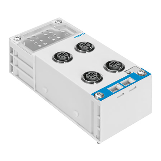
...-IS version only: Approval label Inscription fields Slot for insulating plate Channel status LEDs (green) Fig. 1/3: Display and connecting elements (example M12 connection block) Use identity labels type IBS 6x10 for marking the addresses. Festo P.BE-CPX-P-EA-EN en 1209NH English... -
Page 26: Combination Of Cpx-P Modules And Cpx-P Connection Blocks
CPX-P connection blocks and CPX-P modules for intrinsically safe circuits are additionally provided with a blue marking. For further information regard- ing mechanical coding section 2.2.1 and 2.2.2. Festo P.BE-CPX-P-EA-EN en 1209NH English... -
Page 27: Information Regarding Cable Connection
Provided it is permitted by the national regulations for the potential equalisation concept at the installation location, cable screenings should only be earthed at one point. Festo P.BE-CPX-P-EA-EN en 1209NH English... - Page 28 IP 65: Only use appropriate plug connectors for connection. • Plug connectors from the Festo range of accessories are appropriate for this purpose www.festo.com/catalogue). Tighten the union nut of the plug connector – tightening •...
- Page 29 Screw terminal NECU-L3G8-C2-… Conductor cross section with wire [mm²] 0.25 to 2.5 end sleeve 2 conductors of the same cross [mm²] 0.25 to 1.0 section Insulation-stripping length Dia- meter [mm] Tab. 1/4: Specifications for screw terminal Festo P.BE-CPX-P-EA-EN en 1209NH English...
- Page 30 Fig. 1/4). The terminal will then be unlocked. 2. Insert the wire of the cable into the terminal opening 4 as far as possible. 3. Release the pressure exerted on the release pin. This securely clamps the wire in place. 1-10 Festo P.BE-CPX-P-EA-EN en 1209NH English...
- Page 31 Mechanical coding system for terminal connection To prevent connection errors from occurring during sub- sequent installation and maintenance work, you can mechan- ically code the terminal connector by using a coding system. 1-11 Festo P.BE-CPX-P-EA-EN en 1209NH English...
- Page 32 – insert a coding tab into the recess of the box header. If two coding elements meet at a contact point, insertion of the connector is mechanically locked for this point. 1-12 Festo P.BE-CPX-P-EA-EN en 1209NH English...
- Page 33 - either a coding profile in the plug-in block or a cod- ing tab in the box header. Doing this will reduce the likeli- hood of any mix-ups. A suitable procedure for coding can be found in appendix A.2. 1-13 Festo P.BE-CPX-P-EA-EN en 1209NH English...
- Page 34 1. Overview and connection technology 1-14 Festo P.BE-CPX-P-EA-EN en 1209NH English...
-
Page 35: Mounting And Dismantling
Mounting and dismantling Chapter 2 Mounting and dismantling Festo P.BE-CPX-P-EA-EN en 1209NH English... - Page 36 Mounting and dismantling modules and connection blocks ..2-10 2.2.4 Mounting and dismantling the insulating plate ....2-14 Festo P.BE-CPX-P-EA-EN en 1209NH English...
-
Page 37: General Instructions On Mounting And Dismantling
Mounting and dismantling Note Electronic modules contain electrostatically sensitive devices. Observe the handling specifications for electrostatically • sensitive devices. Discharge yourself from static discharges before assem- • bling or disassembling modules to protect the modules. Festo P.BE-CPX-P-EA-EN en 1209NH English... -
Page 38: Mounting And Dismantling
= module number (counting from left to right - max. 10 modules including bus nodes) For compliance with the required minimum distance in connection with potentially explosive atmo- spheres Tab. 2/1: Configuration of the electrical side of the CPX terminal (-P) Festo P.BE-CPX-P-EA-EN en 1209NH English... - Page 39 If the product is expanded, make sure that the maximum ad- dress capacity is not exceeded. Additional restrictions can apply for certain bus nodes. Observe the rules specified in the bus node description if applicable. Festo P.BE-CPX-P-EA-EN en 1209NH English...
-
Page 40: Mechanically Coding The Connection Block
The top of each CPX-P type electronics module is provided with a fixed coding pin. The configuration and shape of the coding pin depend on the module type and product version. Festo P.BE-CPX-P-EA-EN en 1209NH English... - Page 41 1. Make sure there is no coding element in the connection block. To remove coding elements section 2.2.2. 2. Lay the interlinking block and electronics module Fig. 2/3, 3 ) horizontally on a flat surface. Festo P.BE-CPX-P-EA-EN en 1209NH English...
- Page 42 5. Place the connection block carefully and without tilting onto the electronics module until the coding element en- gages in the designated recess on the underside of the connection block. Festo P.BE-CPX-P-EA-EN en 1209NH English...
-
Page 43: Removing A Coding Element From The Connection Block
( 2 ), e.g. a pin. 3. Replace the cover carefully on the underside of the con- nection block. Locking lever Tool (e.g. pin) Coding element Detach cover on the underside Fig. 2/4: Removing a coding element Festo P.BE-CPX-P-EA-EN en 1209NH English... -
Page 44: Mounting And Dismantling Modules And Connection Blocks
If the thread is damaged, replace the interlinking block. • The screw connection between the sub-base and the manifold sub-base is designed to withstand at least 10 fitting/removal cycles under observance of the instructions. 2-10 Festo P.BE-CPX-P-EA-EN en 1209NH English... - Page 45 IP protection class. This can annul the ignition protection of the device. When replacing modules check the seal and the threads • of the interlinking blocks and, if they are damaged, re- place the corresponding interlinking block. 2-11 Festo P.BE-CPX-P-EA-EN en 1209NH English...
- Page 46 Connection block Screws (Torx-PLUS) Electronics module Contact rails Metal interlinking block Coding pin for mechanical coding Internal electrical interface exemplary representation Fig. 2/5: Mounting the connection block and electronics module 2-12 Festo P.BE-CPX-P-EA-EN en 1209NH English...
- Page 47 Torx screwdriver (size T10) - tightening torque 1 Nm ± 10 %. The lower right-hand screw is used internally as an earthing contact between the interlinking block and the connection block. 2-13 Festo P.BE-CPX-P-EA-EN en 1209NH English...
-
Page 48: Mounting And Dismantling The Insulating Plate
Tab. 2/1). Mounting the insulating plate Press the insulating plate ( 2 ) lightly into the insulating • plate slot ( 1 ) as illustrated ( Fig. 2/6) until the insu- lating plate engages. 2-14 Festo P.BE-CPX-P-EA-EN en 1209NH English... - Page 49 Fig. 2/6: Mounting the insulating plate CPX-P-AB Dismantling the insulating plate To dismantle the insulating plate ( 2 ) you will need to re- move the adjacent connection block. Proceed here as de- scribed in section 2.2.3. 2-15 Festo P.BE-CPX-P-EA-EN en 1209NH English...
- Page 50 2. Mounting and dismantling 2-16 Festo P.BE-CPX-P-EA-EN en 1209NH English...
-
Page 51: Input Module Cpx-P-8De-N
Input module CPX-P-8DE-N-... Chapter 3 Input module CPX-P-8DE-N-... Festo P.BE-CPX-P-EA-EN en 1209NH English... - Page 52 ..... . 3-61 3.4.8 Diagnostics with the handheld CPX-MMI ..... 3-62 Festo P.BE-CPX-P-EA-EN en 1209NH English...
-
Page 53: Functions Of The Input Module Cpx-P-8De-N
3.2.1) For non-intrinsically safe circuits (e.g. for sensors and actuators in a non-ATEX zone). Version with blue markings; only for connecting appropriate intrinsically safe field devices. Observe certification-specific special documentation! Tab. 3/1: Input module CPX-P-8DE-N.. Festo P.BE-CPX-P-EA-EN en 1209NH English... -
Page 54: Installation
– extended process image (current counter readings and frequencies are represented in the PII) – additional parameterisation options for counter inputs and frequency monitoring Factory setting (miniature switch = OFF) Tab. 3/2: Miniature switch positions and size of the process image Festo P.BE-CPX-P-EA-EN en 1209NH English... - Page 55 Observe the handling specifications for electrostatically • sensitive devices. Discharge yourself from static discharges before assem- • bling or disassembling modules to protect the modules. Festo P.BE-CPX-P-EA-EN en 1209NH English...
- Page 56 DIL switch as desired ( Tab. 3/2). 4. Refit the connection block ( mounting chapter, sec- tion 2.2.3; observe the tightening torque!). The set process image becomes effective after switching on the power supply again. Festo P.BE-CPX-P-EA-EN en 1209NH English...
-
Page 57: Pin Allocation Cpx-P-8De-N
Use appropriate T-plug connectors or Duo plugs (plugs with the possibility to connect two cables) to cost-effectively con- nect two Namur sensors or contacts to one socket. Please select the appropriate accessories from our catalogue www.festo.com/catalogue). Festo P.BE-CPX-P-EA-EN en 1209NH English... - Page 58 X2 is in re- verse order (also see assigned LEDs). Note Information regarding the cable connection, shield sup- port and shield earthing can be found in section 1.5. Festo P.BE-CPX-P-EA-EN en 1209NH English...
-
Page 59: Circuitry Examples Cpx-P-8De-N
The two resistors ensure the current lies within the valid operating range in both switching states. Actuated mechanical 10 … 22 kΩ contact 1 … 2 kΩ Fig. 3/3: Connection of actuated mechanical contacts Festo P.BE-CPX-P-EA-EN en 1209NH English... - Page 60 If you are using non-actuated mechanical contacts: Disable the wire break and short-circuit monitoring • function for the respective channels ( Tab. 3/22 and Tab. 3/23). Non-actuated mechanical contact Fig. 3/4: Connection of non-actuated mechanical contacts 3-10 Festo P.BE-CPX-P-EA-EN en 1209NH English...
-
Page 61: Commissioning Instructions
Display text of the process value display on the handheld [Monitoring/Forcing (M)] Replacement value in accordance with parameterisation ( Tab. 3/28 and Tab. 3/29) Short circuit or wire break Tab. 3/6: Process image inputs (PII) – Standard process image 3-11 Festo P.BE-CPX-P-EA-EN en 1209NH English... - Page 62 For digital input channel operating mode (A) – channel 0 … 7 (CH0 … 7) – – – – – – – – – Reserved Tab. 3/7: Process image outputs (PIO) - Standard process image 3-12 Festo P.BE-CPX-P-EA-EN en 1209NH English...
-
Page 63: Processing The I/O Signals - Extended Process Image
C, but with a frequency range up to 10 kHz Current counter readings and frequencies can be represented in the process image inputs (PII) Tab. 3/9). Tab. 3/8: Possible operating modes – Extended process image (miniature switch = ON) 3-13 Festo P.BE-CPX-P-EA-EN en 1209NH English... - Page 64 If the miniature switch of the module is set to ON, bytes 2 to 9 in the PII depict the current counter readings or frequency measurements. Two bytes are occupied in the PII for each counter or frequency measurement ( Tab. 3/9). 3-14 Festo P.BE-CPX-P-EA-EN en 1209NH English...
- Page 65 Additional information regarding configuration and address allocation can be found in the bus node description. Addition- al information regarding counters and frequency measure- ment can be found in section 3.3.5 and 3.3.6. 3-15 Festo P.BE-CPX-P-EA-EN en 1209NH English...
- Page 66 Byte 0 = low byte; byte 1 = high byte; process value display can be parameterised via CPX bus node if necessary ( CPX bus node description) Tab. 3/9: Process image inputs (PII) - Extended process image 3-16 Festo P.BE-CPX-P-EA-EN en 1209NH English...
- Page 67 Reset bit is reset to 0 ( section 3.3.5). The current value is set to 0 ( section 3.3.6). Tab. 3/10: Process image outputs (PIO) - Extended process image 3-17 Festo P.BE-CPX-P-EA-EN en 1209NH English...
-
Page 68: Selecting The Operating Mode
Detailed information regarding the signal extension time and input debounce time parameters can be found in the CPX system description. In the CPX-P-8DE-N-..., however, these parameters are channel-specific and influence the behaviour of an individual channel. 3-18 Festo P.BE-CPX-P-EA-EN en 1209NH English... -
Page 69: Operating Mode B - Counter
The “Counter input” operating mode is specified via the para- meter “Operating mode of the input channel” ( Tab. 3/20). The counter is controlled (start, stop, reset) via the process image outputs ( Tab. 3/10). 3-19 Festo P.BE-CPX-P-EA-EN en 1209NH English... - Page 70 Upon reaching the upper limit value, the corresponding bit is set in byte 0 of the PII ( Tab. 3/9). Upper end of the counting range (maximum value = stop value) Tab. 3/12: Operating methods of an incremental counter 3-20 Festo P.BE-CPX-P-EA-EN en 1209NH English...
- Page 71 Upon reaching the lower limit value, the corresponding bit is set in byte 0 of the PII ( Tab. 3/9). Lower end of the counting range (minimum value = stop value) Tab. 3/13: Possible operating methods of a counter 3-21 Festo P.BE-CPX-P-EA-EN en 1209NH English...
- Page 72 – Signal bit for limit value = 1 (stop value) – Status LED illuminated Status LED flashes as long as the counter is active and the stop value has not yet been reached. Tab. 3/14: Procedure for counters 3-22 Festo P.BE-CPX-P-EA-EN en 1209NH English...
-
Page 73: Operating Mode C, D - Frequency Measurement
The debounce time limits the max. measur- able frequency. At a debounce time of 3 ms, for example, this is approx. 166 Hz. Tab. 3/15: Frequency measurement (operating mode C and D) 3-23 Festo P.BE-CPX-P-EA-EN en 1209NH English... - Page 74 Difference between LLV and ULV: > than 2/T Gate time Difference between LLV and ULV [Hz] [ms] › 200 › 20 › 2 1000 › 2 5000 Tab. 3/16: Required difference between LLV and ULV 3-24 Festo P.BE-CPX-P-EA-EN en 1209NH English...
- Page 75 Reset start/stop bit in the PIO – Signal edges are no longer coun- measurement (start/stop = 0) ted. – Frequency value in PII = 0 – Status LED is off Tab. 3/17: Procedure for frequency measurement 3-25 Festo P.BE-CPX-P-EA-EN en 1209NH English...
-
Page 76: Module Parameters Cpx-P-8De-N
An alteration of the parameter causes a reinitialisation of the respective channel. This parameter is only available in the extended process image (miniature switch = ON). Access is protocol-specific ( bus node description) Tab. 3/18: Overview of module parameters CPX-P-8DE-N.. 3-26 Festo P.BE-CPX-P-EA-EN en 1209NH English... -
Page 77: Instructions For Avoiding Parameterisation Faults
When used in combination with the counter mode and the frequency measurement mode, the function should be stopped before parameterisation by resetting the respective start/stop bits in the PIO. Doing this prevents undefined states during the parameterisation process. 3-27 Festo P.BE-CPX-P-EA-EN en 1209NH English... - Page 78 3. If an error is not reported, the respective function can be used with the loaded parameters (start, stop and, if ne- cessary, reset). In the event of invalid parameters, the previously correct values remain effective. 3-28 Festo P.BE-CPX-P-EA-EN en 1209NH English...
-
Page 79: Module Parameter Of The Input Module Cpx-P-8De-N
0 = inactive [Inactive] 1 = active (presetting) [Active] Comment Implausible parameters are faulty and thus invalid. In the event of invalid para- meters, the previously valid parameters remain effective. Tab. 3/19: Monitoring parameters 3-29 Festo P.BE-CPX-P-EA-EN en 1209NH English... - Page 80 Current counter values and frequencies are shown in the PII (byte 2 … 9). Inputs 4 ... 7 can be used exclusively as digital inputs according to specification EN 60947-5-6 (Namur). Tab. 3/20: Operating mode of the input channel (channel-specific, channel 0 ... 3) 3-30 Festo P.BE-CPX-P-EA-EN en 1209NH English...
- Page 81 If the limit value has been reached (operating mode B) or fallen below/exceeded (operating mode C, D), it is signaled in the PII ( Tab. 3/9). Tab. 3/21: Monitoring limit values (channel-specific, channel 0 ... 3) 3-31 Festo P.BE-CPX-P-EA-EN en 1209NH English...
- Page 82 The behaviour of the signal in the event of a short circuit is specified on a chan- nel-specific basis with the parameter “replacement value” ( Tab. 3/28 and Tab. 3/29). Tab. 3/22: Monitoring short circuit (channel-specific) 3-32 Festo P.BE-CPX-P-EA-EN en 1209NH English...
- Page 83 The behaviour of the signal in the event of a wire break is specified on a channel- specific basis with the parameter “replacement value” ( Tab. 3/28 and Tab. 3/29). Tab. 3/23: Monitoring wire fracture (channel-specific) 3-33 Festo P.BE-CPX-P-EA-EN en 1209NH English...
- Page 84 CPX system description. The parameter, however, is module-specific for many other input modules and influences the behaviour of the entire module. In the CPX-P-8DE-N-... it is a channel-specific parameter that spe- cifies the behaviour of an individual channel. 3-34 Festo P.BE-CPX-P-EA-EN en 1209NH English...
- Page 85 [20 ms] Comment Input debounce times are specified in order to eliminate interfering changes of signal edge during switching procedures (bouncing of the input signal). Tab. 3/26: Input debounce time channel 0 … 3 (channel-specific) 3-35 Festo P.BE-CPX-P-EA-EN en 1209NH English...
- Page 86 [Ch 6] Duct 7 [Ch 7] Values Disabled [Inactive] 3 ms (presetting) [3 ms] 10 ms [10 ms] 20 ms [20 ms] Comment Tab. 3/26 Tab. 3/27: Input debounce time channel 4 … 7 (channel-specific) 3-36 Festo P.BE-CPX-P-EA-EN en 1209NH English...
- Page 87 Replacement value = 0 (presetting) Replacement value = 1 last value of the status bit valid [last value] Reserved Comment Replacement value channel 0 ... 3 Tab. 3/28 Tab. 3/29: Replacement value channel 4 … 7 (channel-specific) 3-37 Festo P.BE-CPX-P-EA-EN en 1209NH English...
- Page 88 If the counter configuration is changed, the counter is initialised! If the debounce time is active, counting is effected to the edge of the debounced signal. Tab. 3/30: Counter configuration (channel-specific, channel 0 … 3) 3-38 Festo P.BE-CPX-P-EA-EN en 1209NH English...
- Page 89 The gate time influences the resolution and the speed at which the measured value is available. Frequency changes can be detected faster at short gate times. Smallest detectable frequency Improved accuracy of measurement Tab. 3/31: Gate time (channel-specific, channel 0 ... 3) 3-39 Festo P.BE-CPX-P-EA-EN en 1209NH English...
- Page 90 Tab. 3/32: Lower limit value (channel-specific, channel 0 …3) The following applies for the limit values: – Lower limit value (LLV) < upper limit value (ULV) – For operating mode C, D: Difference between LLV and ULV: > than 2/T 3-40 Festo P.BE-CPX-P-EA-EN en 1209NH English...
- Page 91 An alteration of the parameter causes an initialisation of the respective channel. – Operating mode B: For additional information section 3.3.5. – Operating mode C, D: For additional information section 3.3.6. Tab. 3/33: Upper limit value (channel-specific, channel 0 … 3) 3-41 Festo P.BE-CPX-P-EA-EN en 1209NH English...
- Page 92 Idle state (also see CPX system description). This parameter is not available with all fieldbus protocols. For input module CPX-P-8DE-N-…: Bit in process image outputs (see Tab. 3/10) Tab. 3/35: Idle mode channel x (channel-specific) 3-42 Festo P.BE-CPX-P-EA-EN en 1209NH English...
- Page 93 “Force state inputs channel x”. The enabling of the Force function for the complete CPX terminal is carried out with the system parameter “Force mode” ( CPX system description). Tab. 3/36: Forcing channel x (channel-specific) 3-43 Festo P.BE-CPX-P-EA-EN en 1209NH English...
-
Page 94: Parameterisation And Signal Display With The Handheld (Mmi)
Input NAMUR IS CPX-P-8DE-N P-8DI-N-X Input NAMUR X CPX-P-8DE-N-IS P-8DI-N-IS-X Input NAMUR IS X Standard process image (factory setting) Extended process image Tab. 3/37: Module identifier on the MMI, module code and sub-module code 3-44 Festo P.BE-CPX-P-EA-EN en 1209NH English... - Page 95 ( section 3.3.1). Further information about the handheld can be found in the description for handheld type P.BE.CPX-MMI-1-..The following image shows an example of the representations for an input module CPX-8DE-N… . 3-45 Festo P.BE-CPX-P-EA-EN en 1209NH English...
- Page 96 Monitoring (M) with standard process image (miniature switch set to OFF) Module data (MD) Monitoring (M) with extended process image (miniature switch set to ON) Fig. 3/6: Special representations for CPX-P-8DE-N.. on the handheld - example 3-46 Festo P.BE-CPX-P-EA-EN en 1209NH English...
- Page 97 Value in hexadecimal notation; MSB = most significant byte; LSB = least significant byte Tab. 3/38: Representation of the extended process image on the handheld For further information about the extended process image please refer to section 3.3.2. 3-47 Festo P.BE-CPX-P-EA-EN en 1209NH English...
-
Page 98: Diagnostics
Error at analogue module/technology module Tab. 3/39: Relevant bit in the status byte The representation of errors in the various bus nodes depends on the protocol ( description for the bus node and/or CPX-FEC). 3-48 Festo P.BE-CPX-P-EA-EN en 1209NH English... -
Page 99: Error Messages Of The Input Module Cpx-P-8De-N
(no er- ror) 1)2) • Upper limit exceeded [Upper limit exceeded] none; error message for in- The parameterised upper lim- formation purposes it value has been reached exceeded; informative (no er- ror) 3-49 Festo P.BE-CPX-P-EA-EN en 1209NH English... - Page 100 Standard CPX error with product-specific error description In operating mode B (counter) this message occurs upon reaching the respective limit value (also refer to the parameter description in Tab. 3/32 and Tab. 3/33). Tab. 3/40: Error elimination 3-50 Festo P.BE-CPX-P-EA-EN en 1209NH English...
-
Page 101: Led Display
Channel error LED (red); one for each channel (8 channels here) Fig. 3/7: LED display of the input module CPX-P-8DE-N.. The display of errors can be suppressed by module paramet- ers ( Tab. 3/21, Tab. 3/22, Tab. 3/23). 3-51 Festo P.BE-CPX-P-EA-EN en 1209NH English... - Page 102 LED flashes Error on the corresponding Eliminate error on the corresponding channel (e.g. short circuit channel; check connected field device or limit value reached) if necessary illuminated Tab. 3/42: Channel error LED 3-52 Festo P.BE-CPX-P-EA-EN en 1209NH English...
- Page 103 In the event of a short circuit or wire break the parameterised value (last signal status or replacement value) is displayed ( Tab. 3/28 and Tab. 3/29). Tab. 3/43: Function of the status LED 3-53 Festo P.BE-CPX-P-EA-EN en 1209NH English...
-
Page 104: Instructions For Parameterising The Input Module Cpx-P-8De-N
Module error position = pre- setting) Module-specific Parameter error monitoring Error no. 29 Parameterisa- tion error Fig. 3/8: Principle of error handling and parameterisation for CPX-P-8DE-N.. - part 1 3-54 Festo P.BE-CPX-P-EA-EN en 1209NH English... - Page 105 Error no. 2 Wire break Short circuit channel x channel x Channel-specific module parameter (switch position indicates the presetting) Channel-specific error Fig. 3/9: Principle of error handling and parameterisation for CPX-P-8DE-N.. – part 2 3-55 Festo P.BE-CPX-P-EA-EN en 1209NH English...
- Page 106 By using the module parameter “replacement value”, you can specify whether the replacement value or the last signal status is to be valid in a diagnostic case ( Tab. 3/28). 3-56 Festo P.BE-CPX-P-EA-EN en 1209NH English...
-
Page 107: Behaviour During The Switch-On Phase (Startup Phase)
LED illuminates or flashes, dependent on error ( Tab. 3/48). The display of errors can be sup- pressed by parameterisation ( Tab. 3/22 and Tab. 3/23). Tab. 3/45: Normal operating status - operating mode A 3-57 Festo P.BE-CPX-P-EA-EN en 1209NH English... - Page 108 ( Tab. 3/19, Tab. 3/21, Tab. 3/22, Tab. 3/23) Retraction of the diagnostics function is only possible by re-parameterisation or resetting the respective counter. Tab. 3/46: Normal operating status - operating mode B 3-58 Festo P.BE-CPX-P-EA-EN en 1209NH English...
- Page 109 LED illuminates or flashes, dependent on error ( also Tab. 3/48). The display of errors can be suppressed by parameterisation ( Tab. 3/19, Tab. 3/21, Tab. 3/22, Tab. 3/23) Tab. 3/47: Normal operating status - operating mode C and D 3-59 Festo P.BE-CPX-P-EA-EN en 1209NH English...
- Page 110 In operating mode B (counter) this message occurs upon reaching the respective limit value (also refer to the parameter description in Tab. 3/32 and Tab. 3/33). Tab. 3/48: Behaviour in the event of an error 3-60 Festo P.BE-CPX-P-EA-EN en 1209NH English...
-
Page 111: Diagnosis Via The Fieldbus Or A Network
Status bits (system status) – I/O diagnostic interface (system diagnosis) – Module diagnosis – Error numbers. Further information on diagnosis can be found in the CPX system manual or in the manual for the bus node. 3-61 Festo P.BE-CPX-P-EA-EN en 1209NH English... -
Page 112: Diagnostics With The Handheld Cpx-Mmi
Current module error (here: none) Fig. 3/11: Diagnostics with the handheld In addition, the handheld also provides access to the dia- gnostic memory. Further information can be found in the de- scription for handheld type P.BE.CPX-MMI-1-..3-62 Festo P.BE-CPX-P-EA-EN en 1209NH English... - Page 113 Technical appendix Appendix A Technical appendix Festo P.BE-CPX-P-EA-EN en 1209NH English...
- Page 114 ......Coding proposal for terminal connection of the CPX-P modules ..Festo P.BE-CPX-P-EA-EN en 1209NH English...
- Page 115 When dealing with product models with corresponding ap- provals and certificates ( product labelling) in conjunction with potentially explosive atmospheres, please observe the information contained in the associated special documenta- tion www.festo.com Downloads Technical documenta- tion). Festo P.BE-CPX-P-EA-EN en 1209NH English...
- Page 116 M12X1 round plug connector or SPEEDCON M12 round plug connectors Only connection technology permitted in accordance with ATEX special documentation! Plug possible in spring-loaded and screw terminal technology Tab. A/1: Technical data of the CPX-P connection blocks Festo P.BE-CPX-P-EA-EN en 1209NH English...
- Page 117 – Reverse polarity protection For operating voltage – Intrinsic current consumption at nominal Typically 75 mA operating voltage – Power failure buffering [ms] 20 (without loss of parameter data) Tab. A/2: Mechanical and electrical characteristic values Festo P.BE-CPX-P-EA-EN en 1209NH English...
- Page 118 – Electrical isolation channel – internal bus Yes, as per EN 50178 – Electrical isolation between intrinsically safe – and non-intrinsically safe circuit parts – Fuse protection (short circuit) Per channel Tab. A/3: Electrical characteristic values - sensor inputs Festo P.BE-CPX-P-EA-EN en 1209NH English...
- Page 119 (frequency measurement channel 1 to 3) – Max. signal frequency [Hz] 1250 – Minimum pulse length/pause [µs] Operating mode D (frequency measurement channel 0) – Max. signal frequency [Hz] 12500 – Minimum pulse length/pause [µs] Tab. A/5: Special functions Festo P.BE-CPX-P-EA-EN en 1209NH English...
- Page 120 – Miniature switch setting: OFF 32/10 32/110 – Miniature switch setting: ON 184/10 184/110 Counter properties Tab. 3/11 Frequency measurement Tab. 3/15 Standard process image Extended process image Tab. A/6: Codes and identification on the handheld Festo P.BE-CPX-P-EA-EN en 1209NH English...
- Page 121 In a modular system with up to 18 plug-in termin- al blocks (max. 9 CPX-P modules permissible), a maximum of 72 coding profiles are required for plug-in terminal blocks and 72 coding tabs are required for box headers. Festo P.BE-CPX-P-EA-EN en 1209NH English...
- Page 122 A. Technical appendix Coding of the box header Coding of the plug-in terminal block A-10 Festo P.BE-CPX-P-EA-EN en 1209NH English...
- Page 123 A. Technical appendix Coding of the box header Coding of the plug-in terminal block A-11 Festo P.BE-CPX-P-EA-EN en 1209NH English...
- Page 124 A. Technical appendix Coding of the box header Coding of the plug-in terminal block Tab. A/7: Coding proposals for terminal connection of the CPX-P modules A-12 Festo P.BE-CPX-P-EA-EN en 1209NH English...
- Page 125 Index Appendix B Index Festo P.BE-CPX-P-EA-EN en 1209NH English...
- Page 126 ............Festo P.BE-CPX-P-EA-EN en 1209NH English...
- Page 127 ......3-21 Display and connecting elements ....Festo P.BE-CPX-P-EA-EN en 1209NH English...
- Page 128 ....... . . Intrinsically safe circuits ..... . XIII, XVII Festo P.BE-CPX-P-EA-EN en 1209NH English...
- Page 129 ......3-32 Mounting the insulating plate ..... 2-15 Festo P.BE-CPX-P-EA-EN en 1209NH English...
- Page 130 3-37 Rules for assembly ....... Festo P.BE-CPX-P-EA-EN en 1209NH English...
- Page 131 ........Wire break monitoring ......3-33 Festo P.BE-CPX-P-EA-EN en 1209NH English...
- Page 132 B. Index Festo P.BE-CPX-P-EA-EN en 1209NH English...
Need help?
Do you have a question about the CPX-P-8DE-N Series and is the answer not in the manual?
Questions and answers