
Subscribe to Our Youtube Channel
Related Manuals for Dobot CR5


Summary of Contents for Dobot CR5
- Page 1 User Guide DOBOT CR5 User Guide Issue: V 3.5.3.1 Date: 2020-05-09 Shenzhen Yuejiang Technology Co., Ltd...
- Page 2 Even if follow this document or any other related instructions, Damages or losses will be happening in the using process, Dobot shall not be considered as a guarantee regarding all security information contained in this document.
- Page 3 DOBOT CR5 User Guide Preface Preface Purpose This Document describes the functions, technical specifications, installation guide and system commissioning of DOBOT CR5 robot system, making it easy for users to fully understand and use Intended Audience This document is intended for: Customer ...
-
Page 4: Table Of Contents
DOBOT CR5 User Guide Contents Contents Security Precautions ....................1 Security Warning Sign ...................... 1 General Security........................ 1 Personal Security ......................5 Overview ........................6 Technical Specifications ....................6 Robot Body Technical Parameters ............... 6 Controller Technical Parameters ................8 Robot Workspace ...................... - Page 5 DOBOT CR5 User Guide Contents Connecting WiFi Module .................. 36 Connecting to Power Supply ................37 Debugging Power On and Off ..................37 Function Description of Software ................. 41 Setting ..........................44 Setting Motion Parameter .................. 44 Setting Safety..................... 51 Remote Control ....................
-
Page 6: Security Precautions
DOBOT CR5 User Guide 1 Security Precautions Security Precautions This topic describes the security precautions that should be noticed when using this product. Please read this document carefully before using the robot for the first time. This product needs to be carried out in an environment meeting design specification. - Page 7 DOBOT CR5 User Guide 1 Security Precautions circuit, otherwise, it is vulnerable to injury the device or the person. You should comply with the local laws and regulations when operating the robot. The security precautions in this document are only supplemental to the local laws and regulations.
- Page 8 DOBOT CR5 User Guide 1 Security Precautions Shenzhen Yuejiang Technology Co., Ltd. assumes no responsibility for robot damage or personal injury caused by failure to follow product instructions or other improper operations. Handling operations such as lifting rings and driving need to use appropriate and reliable lifting equipment.
- Page 9 DOBOT CR5 User Guide 1 Security Precautions If the controller needs to be restarted due to power failure, when restarting, the robot must be manually returned to the initial position of the automatic operation program before restarting the automatic operation.
-
Page 10: Personal Security
DOBOT CR5 User Guide 1 Security Precautions equipment is normally operated. Please ensure that robot and tools are installed correctly. Please ensure that the robot has enough space to move freely. If the robot is damaged, please do not continue to use it. -
Page 11: Overview
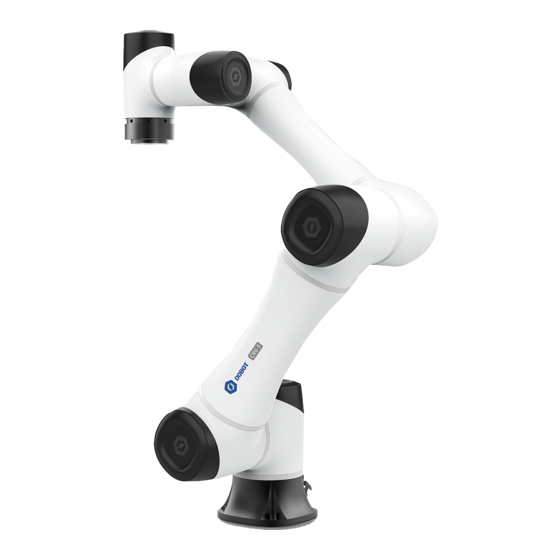
The drag trajectory reproduction function is creatively introduced, which completely reproduces the drag trajectory and reduces the threshold for robot use. DOBOT CR5 has a repeat positioning accuracy of ± 0.03mm, a max load of 5kg, and a joint speed of 180 ° /s. It is a product with the advantages of both industrial robots and collaborative robots. - Page 12 DOBOT CR5 User Guide 2 Overview Rated voltage DC 48V Maximum Speed of 3m/s End-effector ±360° ±360° ±160° Motion Range (° ) ±360° ±360° ±360° 180° /s 180° /s 180° /s Joint Maximum Speed(° /s) 180° /s 180° /s 180° /s...
-
Page 13: Controller Technical Parameters
DOBOT CR5 User Guide 2 Overview Material Aluminum alloy, ABS Controller Technical Parameters Table 2.2 Controller technical parameters Product DOBOT CC161 Axis control 6 axes + external axes Input power 1 PHASE AC 100V~240V AC, 47HZ~63HZ Output power 48V DC, MAX 20A... -
Page 14: End-Effector Size
DOBOT CR5 User Guide 2 Overview Figure 2.2 shows the workspace of CR5 robot. Figure 2.2 CR5 robot workspace End-effector Size Issue V3.5.3.1 (2020-05-09) User Guide Copyright © Yuejiang Technology Co., Ltd... -
Page 15: End-Effector Load Description
DOBOT CR5 User Guide 2 Overview Figure 2.3 End-effector Size End-effector Load Description The robot actuator can bear the load of the cylinder whose center of mass is located at an axial distance of LD80mm from the center of the End -effector and a radial distance of LR60mm and no more than 5kg. - Page 16 DOBOT CR5 User Guide 2 Overview 2.5.1.1 Joint Interpolated Motion Joint interpolated motion includes Go, MoveJ modes. Go/MoveJ: From point A to point B, each joint will run from an initial angle to its target angle, regardless of the trajectory, as shown in Figure 2.5.
- Page 17 DOBOT CR5 User Guide 2 Overview Figure 2.7 Jump mode NOTICE Point A and point B cannot be higher than zLimit. Otherwise, an alarm will be triggered. If point A plus StartHeight or point B plus EndHeight is higher than zLimit, the robot moves up from point A to zLimit or moves down from zLimit to point B directly, the trajectory looks like a door without transition, as shown in Figure 2.8.
-
Page 18: Coordinate System
Cartesian coordinate system. 2.5.2.1 Joint Coordinate System The Joint coordinate system is determined by the motion joints. Figure 2.12 shows the Joint coordinate system of a CR5 robot. All the joints are rotating joints. Issue V3.5.3.1 (2020-05-09) User Guide Copyright © Yuejiang Technology Co., Ltd... - Page 19 2 Overview Figure 2.12 Joint coordinate of a CR5 robot 2.5.2.2 Base Coordinate System The Base coordinate system is determined by the base. Figure 2.13 shows the Base coordinate system of a CR5 robot. Rx , Ry , Rz are the orientation data, which are designated by rotating the tool center point (TCP) around the X, Y, Z axes under the Base coordinate system.
- Page 20 Tool coordinate system which is located at the robot flange without end effector and cannot be changed. And the others can be customized by users. Figure 2.14 shows the default Tool coordinate system of a CR5 robot. R are the orientation data, which are designated by rotating the tool center point (TCP) around the X, Y, Z axes under the default Tool coordinate system.
-
Page 21: Arm Orientation
DOBOT CR5 User Guide 2 Overview Figure 2.15 The default User coordinate system of CR5 robot Arm Orientation Table 2.3 lists the values of the R, D, N arm parameters and their right orientations. Table 2.3 R, D, N identification... -
Page 22: Singularity Point
DOBOT CR5 User Guide 2 Overview Singularity Point When the robot moves under the Cartesian coordinate system, the resultant velocity of the two axes cannot be in any direction if the directions of them are aligned, resulting in that the degrees of freedom of the robot are degraded. -
Page 23: Collision Detection
DOBOT CR5 User Guide 2 Overview Figure 2.17 Shoulder singularity point Elbow singularity point: The Rear arm and Forearm in a straight line. Figure 2.18 Elbow singularity point Collision Detection Collision detection is mainly used for reducing the impact on the robot, to avoid damage to the robot or external equipment. -
Page 24: Key Description On Robot
DOBOT CR5 User Guide 2 Overview automatically when the robot arm hit an obstacle. Key Description on Robot There are function keys and LED indicator on the robot for user to manually control robot. Figure 2.19 Keys on robot Table 2.5 Key description Description ... - Page 25 DOBOT CR5 User Guide 2 Overview If there is an error on robot, the LED indicator turns red. If you switch the robot mode to auto mode on the APP, the LED indicator turns green and blinks. ...
-
Page 26: Electrical Specifications
DOBOT CR5 User Guide 3 Electrical Specifications Electrical Specifications Controller I/O Interface Description A robot controller contains I/O interfaces, for connecting to external equipment, such as air pump, PLC, etc. These I/O interfaces provide 32 digital inputs, 16 digital outputs, 2 analog outputs, and 2 analog inputs, as shown in Figure 3.1. - Page 27 DOBOT CR5 User Guide 3 Electrical Specifications Name Definition Digital input 4 Digital input 5 Digital input 6 Digital input 7 Digital input 8 I/O 0V I / O interface reference level Internal reference level I/O17 Digital input 17 /output 1...
-
Page 28: Emergency Stop I/O Description
DOBOT CR5 User Guide 3 Electrical Specifications Name Definition I/O28 Digital input 28/output 12 I/O29 Digital input 29/output 13 I/O30 Digital input 30/output 14 I/O31 Digital input 31/output 15 I/O32 Digital input 32/output 16 I/O 24V I / O interface 24V power input... -
Page 29: Protective Stop
DOBOT CR5 User Guide 3 Electrical Specifications connect external emergency stop devices. The interface description is as follows: Table 3.2 User emergency stop I/O description Output Interface Input Interface Factory connection Description I/O28 and DI12, I/O29 and DI13 are I/O28(X18:4) DI12(X19:4)... -
Page 30: End I/O Interface Description
DOBOT CR5 User Guide 3 Electrical Specifications Figure 3.2 Remote confirmation tips End I/O Interface Description The cable used for the end interface is our designated cable,the model is Lumberg RKMV 8-354. Figure 3.3 End I/O interface Table 3.5 End I/O description... -
Page 31: Interface Board
DOBOT CR5 User Guide 3 Electrical Specifications DO_1 Digital output 1 Interface Board External Interface Board Description Figure 3.4 shows the interface board of the CC series controller. Table 3.6 lists the description. Figure 3.4 Interface board of the controller Table 3.6 Interface description... -
Page 32: Internal Module Description
DOBOT CR5 User Guide 3 Electrical Specifications Description Power switch of controller For controlling the controller power on and off Power interface For accessing single-phase 1100/220V power supply Heavy-duty connector interface For connecting to robot Power switch of robot For controlling the robot power on and off Internal Module Description A controller contains all necessary functions for controlling the robot. -
Page 33: Digital Input
DOBOT CR5 User Guide 3 Electrical Specifications Module Function protect the servo drive 24V power Turn single-phase 110V/230V AC into 24V DC for powering controller module, I/O module, and other logic modules AC detection Check the AC input and internal DC status of the controller. -
Page 34: Multiplex Digital Input/ Digital Output
DOBOT CR5 User Guide 3 Electrical Specifications Figure 3.6 Simple digital input circuit Table 3.8 Technical specifications Item Specification Input channel 16 channels Connection method Crimping terminal Input type Optical coupling type Input voltage (DC) 0V or 24V±10% Isolation method... -
Page 35: Analog Input
DOBOT CR5 User Guide 3 Electrical Specifications 3.4.4.1 Introduction The multiplex digital input/ digital output interface can be powered by the internal or external power supply. Figure 3.7 shows the simple digital output circuit and Table 3.9 lists the technical specifications. -
Page 36: Analog Output
DOBOT CR5 User Guide 3 Electrical Specifications Figure 3.8 Simple analog input circuit Table 3.10 lists the relation between the DIP switch and analog input. Table 3.10 The relation between the DIP switch and analog input Analog input type Range... -
Page 37: Incremental Encoder Abz Input
DOBOT CR5 User Guide 3 Electrical Specifications Incremental Encoder ABZ Input An encoder is a device that converts angular or linear displacement into electrical signals. Namely, it converts displacement into periodic electrical signals and then converts electrical signals into count pluses. So, the displacements can be measured by the number of pluses. -
Page 38: Installation And Commissioning
DOBOT CR5 User Guide 4 Installation and Commissioning Installation and Commissioning Installation Environment To maintain the controller and robot performance and to ensure the safety, please place them in an environment with the following conditions. Install indoors with good ventilation. -
Page 39: Robot Installation Location
DOBOT CR5 User Guide 4 Installation and Commissioning Figure 4.1 Installation space requirement Robot Installation Location The stability of a robot depends on the installation. You can design the platform according to the size of the hole of the base and the real environment for mounting a robot. The platform must not only bear the robot but also bear the dynamic force by the maximum acceleration. -
Page 40: Connecting Controller And Robot By Heavy Duty Cables
DOBOT CR5 User Guide 4 Installation and Commissioning screws or exposed cables inside the equipment. When the equipment is running, please do not plug or unplug the power and communication cables. Please confirm that the device cable is connected correctly, otherwise it may cause the internal module or external device to malfunction. -
Page 41: Connecting Wifi Module
DOBOT CR5 User Guide 4 Installation and Commissioning Figure 4.3 Connecting emergency stop switch NOTICE Before running a robot, please make sure that the emergency stop switch has been turned on (the red button has been released). Otherwise, the robot cannot work normally. -
Page 42: Connecting To Power Supply
DOBOT CR5 User Guide 4 Installation and Commissioning Figure 4.4 Connecting WiFi module Connecting to Power Supply Plug power cable into controller. As shown in Figure 4.5. Figure 4.5 Connecting to Power Supply Debugging Power On and Off Preparations ... - Page 43 DOBOT CR5 User Guide 4 Installation and Commissioning Figure 4.6 Start robot Figure 4.7 connecting local area network Issue V3.5.3.1 (2020-05-09) User Guide Copyright © Yuejiang Technology Co., Ltd...
- Page 44 DOBOT CR5 User Guide 4 Installation and Commissioning Figure 4.8 Connecting controller and APP The robot icon turns green, indicating that robot enables successfully. Now you can jog robot. Figure 4.9 Enable robot NOTICE The robot arm will move a certain distance during the enabling process. Please ensure that there are no obstacles around the robot.
- Page 45 DOBOT CR5 User Guide 4 Installation and Commissioning Figure 4.10 Disable robot Figure 4.11 Disconnection Issue V3.5.3.1 (2020-05-09) User Guide Copyright © Yuejiang Technology Co., Ltd...
-
Page 46: Function Description Of Software
DOBOT CR5 User Guide 5 Function Description of Software Function Description of Software The robot supports Android/iOS tablet operation. Other types of devices are not currently supported. This manual uses Android tablet as an example. The interface is shown in , and its detailed description is shown in Figure 5.1... - Page 47 DOBOT CR5 User Guide 5 Function Description of Software Figure 5.3 3D illustration of a robotic arm Table 5.1 Cable color description Description Manager APP login personnel are divided into observer, operator, programer and manager, different personnel can operate different...
- Page 48 DOBOT CR5 User Guide 5 Function Description of Software Description programs Monitoring module You can view the status of robot arm, set the output of I/O , set the end parameters of robot arm and other functions Monitoring module shortcuts Robotic arm enable button ON:...
-
Page 49: Setting
DOBOT CR5 User Guide 5 Function Description of Software Setting Before teaching or running robot programs, a series of settings are required, including motion parameter setting, language selecting, user mode selecting and process setting. Setting Motion Parameter 5.1.1.1 Setting Jog You can set the velocity, acceleration or other parameters in different coordinate systems when jogging a robot or running robot programs. - Page 50 DOBOT CR5 User Guide 5 Function Description of Software Figure 5.5 Playback parameters When doing jogging or playback, the method calculating the velocity and acceleration for each axis (in Joint or Cartesian coordinate system) is shown as follows. Actual jogging velocity = the maximum jogging velocity * global velocity rate ...
- Page 51 DOBOT CR5 User Guide 5 Function Description of Software Figure 5.6 Jump parameters 5.1.1.3 Setting User Coordinate System When the position of workpiece is changed or a robot program needs to be reused in multiple processing systems of the same type, you can create coordinate systems on the workpiece to simplify programming.
- Page 52 DOBOT CR5 User Guide 5 Function Description of Software Figure 5.7 Point Line: Confirm a straight line by any two points A and B. The direction from A to B is defined as the positive direction of Y-axis, The Z-axis of Tool coordinate system of which point A is the origin is projected into the vertical plane that confirmed by points A and point B, we can define it as the positive direction of Z-axis.
- Page 53 DOBOT CR5 User Guide 5 Function Description of Software Figure 5.8 Line Area: User coordinate system is created by three-point calibration method. Move the robot to three points A(x1, y1, z1), B(x2, y2, z2), and C(x3, y3, z3). Point A is defined as the origin and the line from point A to Point B is defined as the positive direction of X-axis.
- Page 54 DOBOT CR5 User Guide 5 Function Description of Software Take the establishment of User 1 coordinate system as an example. Prerequisites The robot has been powered on. The APP has been in the manual mode. The robot is enabled.
- Page 55 DOBOT CR5 User Guide 5 Function Description of Software When creating a Tool coordinate system, please make sure that the reference coordinate system is the predefined Tool coordinate system. Tool coordinate system is created by three-point calibration method (TCP +ZX): After the end...
-
Page 56: Setting Safety
DOBOT CR5 User Guide 5 Function Description of Software Figure 5.12 Tool Coordinate page NOTE Rx, Ry, Rz are the orientation data, which are designated by rotating the tool center point (TCP) around the X, Y, Z axes under the selected Tool coordinate system. - Page 57 DOBOT CR5 User Guide 5 Function Description of Software In the safety setting module, you can set safety parameters such as safety hit, power control, joint brake, etc. 5.1.2.1 Safety Hit If the collision detection is activated, the robot arm will stop running automatically when the robot arm hits an obstacle.
-
Page 58: Remote Control
DOBOT CR5 User Guide 5 Function Description of Software Figure 5.15 Joint brake 5.1.2.4 Power Control This function is used to control robot power on or power off. Figure 5.16 Power control Remote Control External equipment can send commands to a robot by different remote control modes, such as remote I/O mode and remote Modbus mode. - Page 59 . The IP address of the Dobot robot Table 5.2 control system and the external device must be on the same network segment. The default IP address of the Dobot robot control system is 192.168.5.1 and the port is 8080. Issue V3.5.3.1 (2020-05-09) User Guide...
- Page 60 DOBOT CR5 User Guide 5 Function Description of Software The robot has been powered on. NOTE The details on how to connect external equipment and use it are not described in this topic. Procedure The remote control page is displayed, as shown in Figure 5.17.
- Page 61 DOBOT CR5 User Guide 5 Function Description of Software Table 5.3 Specific Modbus register description Register address (Take a PLC Register address (Robot Description as an example) system) Coil register 00001 Start running in the remote Modbus mode 00002 Pause running in the remote...
-
Page 62: Homing
DOBOT CR5 User Guide 5 Function Description of Software Figure 5.18 Remote control page Right now, only the emergency stop button and the real-time coordinates displaying section are available. The robot will move as the selected offline project. If the stop signal is triggered, the remote Modbus mode will be invalid. -
Page 63: Running Log
DOBOT CR5 User Guide 5 Function Description of Software Figure 5.19 Homing page If the origin of robot has been changed, you need to reset it. Switch Back to home to Set home position, and put the robot in the original position and click Home to set origin of the robot. This feature only supports administrator settings. -
Page 64: Setting Software
DOBOT CR5 User Guide 5 Function Description of Software Figure 5.21 Running log Setting Software 5.1.6.1 Setting APP lock You can set APP lock screen time as needed. If the software is not operated within this time period, the system will automatically lock the screen. The unlock password defaults to: 000000. - Page 65 DOBOT CR5 User Guide 5 Function Description of Software Figure 5.23 Import/export file 5.1.6.3 Setting Network You can set the IP, port and password of the server (WiFi) according to actual needs. The default IP is 192.168.1.6 and the port is 22000.
-
Page 66: Hand-Hold Teach
DOBOT CR5 User Guide 5 Function Description of Software Figure 5.25 Setting controller IP Hand-Hold Teach You can drag robot to teach by APP or function keys on the end of robot. For function key details, please refer to 2.6 Key Description on Robot. -
Page 67: Monitor
DOBOT CR5 User Guide 5 Function Description of Software Button Description Click this button to save trajectory Click this button to start or stop playback. Select the recorded trajectory, and click Path playback to start trajectory playback You can set Path playback loop-time on the hand-hold teach page, the default value is 1... -
Page 68: Robot Status
DOBOT CR5 User Guide 5 Function Description of Software Figure 5.27 I/O Monitor Robot Status You can check temperature, voltage, current of robot and so on. Figure 5.28 Robot status Controlling End-effectors 5.3.3.1 Setting Gripper You can enable and control gripper in this page. Select Enable to enable gripper, select Open or Close to open or close gripper. - Page 69 DOBOT CR5 User Guide 5 Function Description of Software Figure 5.29 Set gripper 5.3.3.2 Setting End-loading of Robot Set LoadValue in this page, the value range is 0 kg to 5 kg, Other parameters do not need to set. Figure 5.30 set end-loading of robot 5.3.3.3 Setting Six-axis Force Sensor...
- Page 70 DOBOT CR5 User Guide 5 Function Description of Software Figure 5.31 Setting Six-axis Force Sensor Calibration Figure 5.32 Calibrate X-axis Issue V3.5.3.1 (2020-05-09) User Guide Copyright © Yuejiang Technology Co., Ltd...
- Page 71 DOBOT CR5 User Guide 5 Function Description of Software Figure 5.33 Calibrate X-axis Figure 5.34 Calibrate Y-axis Issue V3.5.3.1 (2020-05-09) User Guide Copyright © Yuejiang Technology Co., Ltd...
- Page 72 DOBOT CR5 User Guide 5 Function Description of Software Figure 5.35 Calibrate Y-axis Figure 5.36 Calibrate Z-axis Issue V3.5.3.1 (2020-05-09) User Guide Copyright © Yuejiang Technology Co., Ltd...
-
Page 73: Programming
For details, please refer to 6.10Six-axis Force Sensor . Programming Program Description CR5 robot supports script programming, graphics programming, and Blockly programming which use the Lua language as the programming language. Figure 5.38 Program Description Issue V3.5.3.1 (2020-05-09) User Guide Copyright ©... - Page 74 DOBOT CR5 User Guide 5 Function Description of Software Figure 5.39 Programming process Script Programming Script programming uses Lua as the programming language, as shown in Figure 5.40. Figure 5.40 Script programming Issue V3.5.3.1 (2020-05-09) User Guide Copyright © Yuejiang Technology Co., Ltd...
- Page 75 DOBOT CR5 User Guide 5 Function Description of Software Table 5.5 Button description Button Description Click this button to write program Click this button to debug program Click this button to set teaching points. Click this button to delete thread...
-
Page 76: Program Example
DOBOT CR5 User Guide 5 Function Description of Software and easy to understand. Figure 5.42 Blockly programming Program Example This section takes script programming as an example to describe how to program. We call Go command to make the robot move between point P1 and point P2 circularly. - Page 77 DOBOT CR5 User Guide 5 Function Description of Software Arm is the arm orientation, Tool is tool coordinate system, User is User coordinate system. Figure 5.44 Save teaching points Table 5.6 Button description Button Description Add a teaching point Delete a teaching point...
- Page 78 DOBOT CR5 User Guide 5 Function Description of Software Figure 5.45 Edit program Figure 5.46 Finish writing Issue V3.5.3.1 (2020-05-09) User Guide Copyright © Yuejiang Technology Co., Ltd...
- Page 79 DOBOT CR5 User Guide 5 Function Description of Software Figure 5.47 Debug Table 5.7 Button description Button Description Start button, click it to run program Pause button, click it to pause program Run a program step by step, you can run a program step by step by setting a breakpoint Issue V3.5.3.1 (2020-05-09)
-
Page 80: Program Language
DOBOT CR5 User Guide 6 Program Language Program Language CC series controller encapsulates the robot dedicated API commands for programming with Lua language. This section describes commonly used commands for reference. Arithmetic Operators Table 6.1 Arithmetic operator Command Description Addition... -
Page 81: General Keywords
DOBOT CR5 User Guide 6 Program Language Table 6.3 Logical operator Command Description Logical OR operator Logical NOT operator Logical AND operator General Keywords Table 6.4 General keyword Command Description break Break out of a loop local Define a local variable, which is available in the current... -
Page 82: Motion Commands
DOBOT CR5 User Guide 6 Program Language The robot global variables can be defined in the global.lua file, including global functions, global points, and global variables. Global function: function exam() print("This is an example") Define a joint coordinate point, of which R sets to 1, D sets to -1, N sets to 0, Cfg sets to 1, the User and Tool coordinate systems are both default coordinate systems. - Page 83 DOBOT CR5 User Guide 6 Program Language Command Description a straight line under the Cartesian coordinate system Move from the current position to the offset position in a point-to-point mode under the Cartesian coordinate system MoveJR Move from the current position to the offset position in...
- Page 84 DOBOT CR5 User Guide 6 Program Language coordinate system Parameter Required parameter: P: Indicate the joint angle of the target point, which cannot be obtained from the TeachPoint page. You need to define the joint coordinate point before calling this command Optional parameter: ...
- Page 85 DOBOT CR5 User Guide 6 Program Language Description Move from the current position to a target position in an arc interpolated mode under the Cartesian coordinate system This command needs to combine with other motion commands, to obtain the starting point of an...
- Page 86 DOBOT CR5 User Guide 6 Program Language AccelS: Acceleration rate. Value range: 1 - 100 Arch: Arch index. Value range: 0 - 9 Start: Lifting height Zlimit: Maximum lifting height End: Dropping height SYNC: Synchronization flag. Value range: 0 or 1. If SYNC is 0, it indicates asynchronous execution, this command has a return immediately after calling it, regardless of the command process.
- Page 87 DOBOT CR5 User Guide 6 Program Language execution, this command has a return immediately after calling it, regardless of the command process. If SYNC is 1, it indicates synchronous execution. After calling this command, it will not return until it is executed completely...
- Page 88 DOBOT CR5 User Guide 6 Program Language Table 6.16 GoR command =1 ”) SYNC Function GoR({OffsetX, OffsetY, OffsetZ},” User=1 Tool=2 CP=1 Speed=50 Accel=20 Description Move from the current position to the offset position in a point-to-point mode under the Cartesian...
-
Page 89: Motion Parameter Commands
DOBOT CR5 User Guide 6 Program Language MoveJR({20,20,10,0},"SYNC=1") Table 6.18 MoveR command Function MoveR({OffsetX, OffsetY, OffsetZ},” User=1 Tool=2 CP=1 SpeedS=50 AccelS=20 SYNC =1”) Description Move from the current position to the offset position in a straight line under the Cartesian... - Page 90 DOBOT CR5 User Guide 6 Program Language Command Description Arch Set the index of sets of parameters (StartHeight, zLimit, EndHeight) in Jump mode Set the continuous path function LimZ Set the maximum lifting height in the Jump mode Table 6.20 Accel command...
- Page 91 DOBOT CR5 User Guide 6 Program Language Table 6.23 SpeedS command Function SpeedS(R) Description Set the acceleration rate. This command is valid only when the motion mode is Move, Arc3, or Circle3 Parameter R: Percentage. Value range: 1 - 100...
-
Page 92: Six-Axis Force Sensor Commands
DOBOT CR5 User Guide 6 Program Language Figure 6.1 Continuous path Table 6.26 LimZ command Function LimZ(zValue) Description Set the maximum lifting height in Jump mode Parameter zValue: The maximum lifting height which cannot exceed the Z-axis limiting position of the... - Page 93 DOBOT CR5 User Guide 6 Program Language Table 6.29 Six-axis force sensor spiral command Function Spiral(P, User, Tool, Direction, SpeedC, Force, Insertion, Perturn, PeckMode, MaxValue) Description The robot arm performs a spiral motion between the current position and the specified position to find the hole position.
-
Page 94: Input/Output Commands
DOBOT CR5 User Guide 6 Program Language Parameter P: the specified position User: User coordinate system, value range: 0~9 Tool: Tool coordinate system, Value range: 0~9 Direction: Jack direction (0: Forward, 1: Reverse) SpeedC: Jack speed(mm/s) ... - Page 95 DOExecute Set the status of the digital output port (Immediate command) NOTE Dobot robot system supports two kinds of commands: Immediate command and queue command: Immediate command: The robot system will process the command once received regardless of whether there is the rest commands processing or not in the current controller;...
-
Page 96: Program Managing Commands
DOBOT CR5 User Guide 6 Program Language Description Set the status of digital output port (Queue command) Parameter index: Digital output index. Value range: 1- 24 ON/OFF: Status of the digital output port. ON: High level; OFF: Low level... - Page 97 DOBOT CR5 User Guide 6 Program Language Table 6.38 Sleep command Function Sleep(time) Description Set the delay time for all commands Parameter time: Delay time. Unit: ms Example while true do Speed(100) Go(P1) sleep(3) Speed(100) Accel(40) Go(P2) sleep(3) Table 6.39 Pause command...
- Page 98 DOBOT CR5 User Guide 6 Program Language Table 6.40 Star timing command Function ResetElapsedTime() Description Start timing after all commands before this command are executed completely. Use in conjunction with ElapsedTime() command For example: Get the execution time that a piece of code takes...
-
Page 99: Pose Getting Command
DOBOT CR5 User Guide 6 Program Language Description Get the current time Parameter None Return Current time Example Go(P2, " Speed=100 Accel=100") local time1=Systime() for i=1,10 do Jump(P1, " Speed=100 Accel=100 Start=0 End=0 ZLimit=185") Jump(P2, " Speed=100 Accel=100 Start=0 End=0 ZLimit=185") -
Page 100: Tcp
DOBOT CR5 User Guide 6 Program Language Description Get the current pose of the robot under the Joint coordinate system Parameter None Return Joint coordinate of the current pose Example local armPose local joint = GetAngle() --Get the current pose local liftPose = {armOrientation = armPose , joint = {joint.joint[1], joint.joint[2], joint.joint[3],... - Page 101 DOBOT CR5 User Guide 6 Program Language Return 0: TCP connection is successful 1: Input parameters are incorrect 2: Socket object is not found 3: Timeout setting is incorrect 4: If the robot is set as a client, it indicates that the connection is wrong. If the robot is set...
- Page 102 DOBOT CR5 User Guide 6 Program Language Return 0: Sending data is successful 1: Sending data is failed Example Please refer to Program 6.1 and Program 6.2 Table 6.49 Release TCP network command Function TCPDestroy(socket) Description Release a TCP network...
- Page 103 DOBOT CR5 User Guide 6 Program Language else print("Read error ".. err) break else print("Create failed ".. err) TCPDestroy(socket) else print("Create failed ".. err) Program 6.2 TCP client demo local ip="192.168.5.25" // External equipment such as a camera is set as the server...
-
Page 104: Udp
DOBOT CR5 User Guide 6 Program Language else print("Create failed ".. err) TCPDestroy(socket) else print("Create failed ".. err) Table 6.50 Create UDP network command Function err, socket = UDPCreate(isServer, IP, port) Description Create a UDP network Only a single connection is supported Parameter isServer: Whether to create a server. - Page 105 DOBOT CR5 User Guide 6 Program Language Return err: 0: Receiving data is successful 1: Receiving data is failed Recbuf: Data buffer Example Please refer to Program 6.3 and Program 6.4 Table 6.52 Send data command Function UDPWrite(socket, buf, timeout)
- Page 106 DOBOT CR5 User Guide 6 Program Language err, RecBuf = UDPRead(socket, 0) //Server receives the data from client if err == 0 then Go(P1) // Start to run motion commands after the server receives the data Go(P2) print(buf) else print("Read error ".. err) break;...
-
Page 107: Modbus
DOBOT CR5 User Guide 6 Program Language else print("Create failed ".. err) Modbus Modbus Register Description Modbus protocol is a serial communication protocol. The robot system can communicate with external equipment by this protocol. Here, External equipment such as a PLC is set as the Modbus master, and the robot system is set as the salve. -
Page 108: Command Description
DOBOT CR5 User Guide 6 Program Language Discrete input register Discrete input register Data type Description address (e.g.: PLC) address(Robot system) 10004 Running state 10005 Alarm state 10006-10999 5-998 Reserved 11000-14096 999-4095 User-defined Input register Table 6.55 Input register description... - Page 109 DOBOT CR5 User Guide 6 Program Language Example Read 5 coils starting at address 0 Coils = GetCoils(0,5) Return: Coils={1,0,0,0,0} As shown in Table 6.52, it indicates that the robot is in the starting state Table 6.58 Set coil register command...
- Page 110 DOBOT CR5 User Guide 6 Program Language Table 6.60 Read input register command Function GetinRegs(addr, count, type) Description Read the input register value with the specified data type from the Modbus slave Parameter addr: Starting address of the input registers. Value range: 0 - 4095 count: Number of the input registers to read.
- Page 111 DOBOT CR5 User Guide 6 Program Language Example Example 1: Read a 16-bit unsigned integer starting at address 2048 data = GetHoldRegs(2048,1) Example 1: Read a 32-bit unsigned integer starting at address 2048 data = GetInRegs(2048, 1, “U32”) Table 6.62 Set holding register command...
Need help?
Do you have a question about the CR5 and is the answer not in the manual?
Questions and answers