Table of Contents
Advertisement
Quick Links
Advertisement
Table of Contents

Related Manuals for Huvitz HOCT-1


Summary of Contents for Huvitz HOCT-1
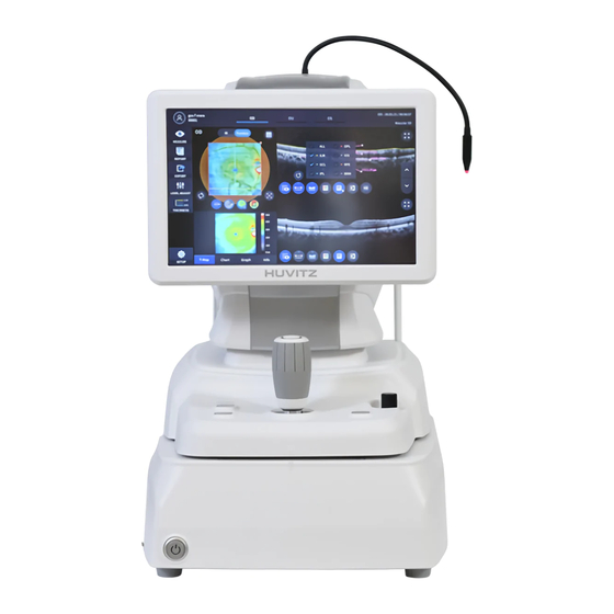
- Page 1 OPTICAL COHERENCE TOMOGRAPHY HOCT-1/1F USER MANUAL...
- Page 2 HUVITZ reserves the right to make changes in its products or product specifications at any time and without prior notice, and is not required to update this documentation to reflect such changes.
- Page 3 HOCT-1/1F CONTENTS SAFETY PRECAUTIONS ............................. 5 1.1. Overview ......................................5 Symbol Information ..............................6 2.1. Usage Precautions..................................... 9 2.2. Environmental Considerations ................................ 12 2.3. Safety Precautions ................................... 14 INTRODUCTION ................................ 17 3.1. System Outline ....................................17 3.2. Intended Use ....................................17 3.3.
- Page 4 8.2. Specifications ....................................148 8.3. Drawings of System ..................................149 EMC INFORMATION ..............................150 SERVICE INFORMATION ............................152 SOFTWARE LICENSE AGREEMENTS ........................153...
- Page 5 HOCT-1/1F SAFETY PRECAUTIONS 1.1. Overview Safety is everyone’s responsibility. The safe use of this instrument is largely dependent upon the installers, users, operators, and managers. It is prerequisite to read and understand these specifications before installing, using, cleaning, fixing or revising. Fully understanding the whole instructions must be the first priority. For this reason, the following safety notices have been placed appropriately within the text of this manual to highlight safety related information or information requiring special emphasis.
- Page 6 Symbol Information The International Electrotechnical Commission (IEC) has established a set of symbols for medical electronic equipment which classify a connection or warn of any potential hazards. The classifications and symbols are shown below. Symbol Indication This symbol identifies a safety note. Ensure you understand the function of this control before using it.
- Page 7 HOCT-1/1F WEEE Symbol – EU only Disposal of your old appliance When this crossed-out wheeled bin symbol is attached to a product it means the product is covered by the European Directive 2002/96/EC. All electrical and electronic products should be disposed of...
- Page 8 Alternating Current (Courant alternative) Consult instructions for use (Consulter les instructions d'utilisation) The United States and Canada have mutual-recognition agreements. Therefore, if certified using a Canadian specification (CSA) for UL, the certification mark for the product will be a C-UL certification mark which means CSA specification compliance as follows.
- Page 9 HOCT-1/1F 2.1. Usage Precautions This equipment has been developed and tested in conformity with domestic & international safety standards and regulations, which guarantees the high stability of this product. This guarantees a very high degree of safety for this device. The legislator expects us to inform the user expressively about the safety aspects in dealing with the device.
- Page 10 CAUTION During the Anterior segment image operation, pull the joystick toward the operator before adjusting the alignment. Move the body to align patient’s eye. Move the body slowly while watching patient’s eye and body, because working distance is just 15mm that the front lens is very close to patient's eye. CAUTION This instrument includes lithium battery.
- Page 11 HOCT-1/1F CAUTION The equipment is a Class I LED Product. The LED used for the equipment is safe under expected use conditions including situation such as looking into the LED using optical equipment. However, observe the following precautions when using the equipment ...
- Page 12 Where the instrument is exposed to chemical material or explosive gas. Be cautious so that things like dust and metal do not fall inside the instrument. Don’t disassemble or open the product. HUVITZ does not take responsibility for the possible problems...
- Page 13 HOCT-1/1F Don’t plug the AC power cable into the outlet unless all parts of the instrument are completely connected. Otherwise, it will cause severe damage on the instrument. Pull out the power cable with holding the plug, not the cord.
- Page 14 This instrument must be connected with the accessories supplied by HUVITZ. If you are to use other accessories, their safety or usability must be checked and proved by their manufacturers or HUVITZ.
- Page 15 HOCT-1/1F Do not apply excessive force to cable connections. If the cable does not connect easily, make sure that the connector (plug) is appropriate for the receptacle (socket). If you caused any damage to a cable connector(s) or receptacle(s), let the damage(s) be repaired by an authorized service technician.
- Page 16 Do not touch directly if an operator has a hand injury or a significant allergic reaction to the material used in the operation contact part. Part Name Material LCD Touch Glass pannel Joystick / ABS + Silicon, button Aluminum(A6061 T6) Power switch PC + PA66 Cover...
- Page 17 3.2. Intended Use The HOCT-1, HOCT-1F is intended for use to aid in the diagnosis and management of ocular diseases such as macular holes, cystoid macular edema, diabetic retinopathy and aged related macular degeneration which are occurred at a macular, an optic disk, an inner structure of retina, and a cornea.
- Page 18 3.6. Operating Principles 3.6.1. Fundus image The anterior of an eye is illuminated by IR light, the posterior of an eye is illuminated by an infrared light and a white LED, of which lightings are emitted by the fundus illumination optical system. The fundus observation/photography optical system forms and makes an image with image sensors, which images are observed and manipulated with the display panel.
- Page 19 HOCT-1/1F System Overview 4.1. Configuration and Functions Front View ⑪ ⑩ ① ④ ② ③ ⑤ ⑥-2 ⑥-1 ⑦ ⑨ ⑨-1 ⑨-2 Part Name Description Display Monitor for displaying captured image and user interface icon. Chinrest button Button for moving chinrest up and down.
- Page 20 Rear View ② ④-1 ① ① ④-2 ⑧ ③ ⑧-3 ⑧-4 ⑧-1 ⑧-2 ⑧-5 Part Name Description Forehead rest Rubber for fix patient’s head. Headrest External LED External LED for fixing patient’s eyes. Chinrest For fixing patient’s chin. Lens for passing illumination light from body and reflected light Objective lens from patient’s eye.
- Page 21 HOCT-1/1F Bottom View ① Part Name Description Base Packing lock Lock for fixing body and base during transportation. (2 points)
- Page 22 4.2. Main Body Screen Description 4.2.1. OCT/Fundus mode (HOCT-1F only) Observation screen ❶ ❷ ❸ ⓫ ❹ ⓬ ❺ ❻ ❼ ❽ ⓭ ⓮ ❾ ⓯ ⓲ ❿ ⓰ ⓱ Name Function Shows the information of patient ID and name. Go back to patient list by clicking Patient information the icon.
- Page 23 HOCT-1/1F - Fundus mode: Single macular, Single disc, Widefield Panorama Scan direction Horizon, vertical changes are possible. Follow-up Follow up the scan position that was used&saved. Reset scan position Reset scan position to center. Focus Move in accordance with focus of patient’s eye.
- Page 24 OCT image Show captured OCT image. 4.2.2. OCT mode Observation screen ❶ ❷ (Refer ‘4.2.1. OCT/Fundus mode – Observation screen’ for uncommented item) Name Function DISC T Tracking the best status with disc while scanning. Signal Level Choose the signal strength.
- Page 25 HOCT-1/1F Confirmation screen (Refer ‘4.2.1. OCT/Fundus mode – Confirmation screen’ for uncommented item) 4.2.3. Fundus mode (HOCT-1F only) Observation screen ❶ ❸ ❷ (Refer ‘4.2.1. OCT/Fundus mode – Observation screen’ for uncommented item) Name Function Select capture mode. Capture mode - Single macular: Capture one fundus image at macular fixation.
- Page 26 - Widefield Panorama: Capture maximum 7 images and stitch it. IR.En Change brightness of IR fundus image Optimize Find focus position automatically by split focus image. Confirmation screen ❶ (Refer ‘4.2.1. OCT/Fundus mode – Confirmation screen’ for uncommented item) Name Function Fundus information Display setting information of fundus image.
- Page 27 HOCT-1/1F (Refer. OCT/Fundus mode – Observation screen’ for uncommented item) Name Function Disc tracking box Tracking the best status with disc box while scanning. Scan region It is sized with scan range. Confirmation screen (Refer ‘4.2.1. OCT/Fundus mode – Confirmation screen’ for uncommented item)
- Page 28 Installation Procedure 5.1. System installation 1. Place the main body unit on a stable table. 2. Loosen the two packing lock screw under the main body. Packing lock 3. Unscrew the user lock lever on the body. Joystick User lock 4.
- Page 29 HOCT-1/1F External LED Headrest 7. If needed, connect external devices. (1) Open ‘COVER BASE VENT’ on the left bottom of base with screw driver. (2) If needed, connect mouse or keyboard (3) Connect communication cable of external device. (4) Close ‘COVER BASE VENT’ with screw driver.
- Page 30 12. Turn on the main body by pressing power switch (I position) 13. Turn on the internal PC by pressing power button. Power button Power switch 14. Check there is no error during initialize process. Wait for until the initialization is complete. 15.
- Page 31 HOCT-1/1F Operation 6.1. Software 1. Input user ID and password for login. 2. Press resist patient icon ( ) and input patient information. If patient is resisted already, skip this step. 3. Select patient and check patient information is correct.
- Page 32 4. If you want to send patient information to a web viewer or delete patient information, select the circle next to the ID and press the TRANSFER icon or DELETE icon. 5. When you select a patient, the screen changes. 6.
- Page 33 HOCT-1/1F 6.2. SETUP Mode 6.2.1. General Setting System Settings Device Name Set Device Name. Server IP Web Viewer Server IP address setting. Sever Port Web Viewer Server port setting. Sleep Time Sleep mode setting. Set the function to transfer the measured data to Web Auto Data Trans Viewer automatically.
- Page 34 The function to modify and add the operators & Staff Management physicians information. Auto Import The function to set the auto import. Auto Import Path The function to designate the import path. Auto Import Interval The function to set the interval of import. Measure Settings.
- Page 35 HOCT-1/1F Retina Tracking Range Set the tracking range in the Angio tracking mode. Noise Reduction Set the noise reduction rate. Voice Guide Set the voice guide and voice guide language. Scan Pattern Settings the default pattern domain of OCT scan Pattern Domain measurement to be either macular, disc, or anterior.
- Page 36 mode with the option turned on, the disk and cup positions are displayed above the Bscan image. Relative map scale Set the way how represent the relative map. Text color Set the measurement value text(ruler value) color. Report Settings Report Logo Add the Logo into report.
- Page 37 HOCT-1/1F 6.2.2. Angiography-module setting Click Angio button at [SET UP] – [Info.] page. Put in License Code and Click [OK]button. Then, pop up the certification message window.
- Page 38 6.3. DICOM SETUP Mode Worklist Setting IP Address of the PC where the server program is Server IP installed. Server Port Set Port Number. Server AE Set Server AE. Client AE Set Client AE. MPPS Setting IP Address of the PC where the server program is Server IP installed.
- Page 39 HOCT-1/1F Storage Setting IP Address of the PC where the server program is Server IP installed. Server Port Set Port Number. Server AE Set Server AE. Client AE Set Client AE. General Setting Manufacturer Set the name of the manufacturer.
- Page 40 6.4. General Operation Clean headrest and chinrest with a clean cotton swab or gauze. Remove a single sheet of chinrest paper if the chinrest paper is used. Align left/right index mark (B) and front index mark (A) of body and base with joystick. Let the patient sit in front of instrument.
- Page 41 HOCT-1/1F (1) Set capture mode with the capture mode tabs ( OCT/Fundus Capture OCT and fundus image simultaneously. (HOCT-1F only) Capture OCT image. Fundus (HOCT-1F only) Capture Fundus image. (2) Set capture region with the capture region combo box (...
- Page 42 Scan along 24 lines in the square area centered at macular. Scan a rectangular area closely. Scan a rectangular area. Scan along 12 radial lines centered at disc.
- Page 43 HOCT-1/1F Scan along 24 lines in the square area centered at disc. Scan a rectangular area closely Scan along a circle centered at optic disc. Scan a rectangular area. Scan along a line for cornea.
- Page 44 Scan along 12 lines for cornea. <Scan Options> Range: Choose scan range from 6mm, 4.5mm, 9mm, or 12mm. • AScan Points: Choose the number of A-scans that constitute one B-scan. Possible options are 1024, • 512, or 256. Bscan Lines: Choose the number of B-scans that constitute one measurement. Possible options •...
- Page 45 HOCT-1/1F < Scan Range : 6 > < Scan Range : 6x6 > < Scan Range : 9 > < Scan Range : 9x9 > < Scan Range : 12 > < Scan Range : 12x9 > Ascan, Bscan: Number of horizontal and vertical scan points in the scan area.
- Page 46 (5) Set auto tracking mode. Auto tracking is on. Auto tracking is off. If auto tracking is on, patient’s eye is automatically tracked to center and focused when patient’s eye is • inside tracking region. Auto tracking is not supported for anterior capture mode. •...
- Page 47 HOCT-1/1F Instruct patient to watch internal fixation LED to fix patient eyes. Also, instruct patient to open eye widely, not to blink. Move body with joystick until patient’s eye appears on the screen. Set the alignment and focus. (1) Move the body up/down and left/right with joystick until ring of 16 blue align dot (A) and ring of 8 white Mire dot (B) are concentric.
- Page 48 (4) If auto tracking is on, alignment and focus is automatically accomplished in tracking region. (5) If orange arrow (A) appears during auto tracking, it means auto tracking module go to the limit of tracking region. In that case, move body to the arrowed direction with joystick. ○...
- Page 49 HOCT-1/1F ① Check previous/next OCT image by move scan position handle. ② Check continuous OCT image continuously by pressing play image icon ( ③ Check SSI for image quality. SSI (Scan Signal Index) indicates level of image quality. SSI means signal to background ratio and displayed on a scale of 10 with a bar graph.
- Page 50 icon changes to optimize icon ( (2) Optimize OCT signal by pressing optimize icon on the screen or optimize button on the body (A). (3) Adjust the vertical position of retina image in the screen by moving reference mirror using slide bar (4) Press the button on joystick to capture image.
- Page 51 HOCT-1/1F Try moving internal fixation target position by pressing fixation icon ( ) and changing position of green cross ( ) if needed. When green cross position changes, the position of internal fixation target is also changed. Try to change scan position by dragging scan range while scan range icon turned on. If reset scan position icon ( ) is pressed, scan position moves to the default center position.
- Page 52 Try moving internal fixation target position by pressing fixation icon ( ) and changing position of green cross ( ) if needed. When green cross position changes, the position of internal fixation target is also changed.
- Page 53 HOCT-1/1F 6.5. Anterior segment image operation (optional) 6.5.1. Preparation for anterior segment operation Check the lens surface of anterior segment adapter is clean. Thread anterior segment adapter (A) to objective lens holder (B), and check there is no tilting or misalignment of adopter.
- Page 54 Capture image and check image quality (in anterior radial mode). (1) Alignment and focus. ① Move body with joystick slowly to align anterior scan line (A) and center of patient’s eye (B). ② Start OCT scan by pressing scan start icon ( ③...
- Page 55 HOCT-1/1F ① Check previous/next OCT image by move scan position handle. Check continuous OCT image continuously by pressing play image icon ( ) if needed. ② ③ Check SSI for image quality if needed. SSI (Scan Signal Index) indicates level of image quality. SSI means signal to background ratio and displayed on a scale of 10 with a bar graph.
- Page 56 (2) Measuring anterior chamber angle. Optimize OCT signal by pressing optimize icon on the screen ( ) or optimize button on the body ① (A). ② For enhancing OCT signal, move position of reference mirror by pressing arrow of REF.M icon ) if needed.
- Page 57 HOCT-1/1F flash icon ( ) in observation mode. If fundus image is too dark because of small pupil size of patient, try small pupil mode by using small pupil icon ( ) in observation mode. Try moving internal fixation target position by pressing fixation icon (...
- Page 58 6.6. Angiography image operation (optional) The first procedure is same as ‘6.4 General Operation: procedure 2 ~ 7’. On the angio mode, function of auto tracking is additionally available while scanning. • Capture image and check image quality (in angiography mode). (1) Alignment and focus.
- Page 59 HOCT-1/1F (3) Check image quality. ① Check previous/next OCT image by move scan position handle. ② Check continuous OCT image continuously by pressing play image icon ( ) if needed. Check SSI for image quality if needed. ③ SSI (Scan Signal Index) indicates level of image quality. SSI means signal to background ratio and displayed on a scale of 10 with a bar graph.
- Page 60 6.7. Analyze 6.7.1. Entering Analysis screen Analysis immediately after scanning. To enter analyze mode from measurement confirm screen, press the analyze icon ( ) from the captured image screen. Analysis from measurement list. Select a measurement to analyze by clicking and press the analyze icon (...
- Page 61 HOCT-1/1F 6.7.2. OCT Macular 3D Analysis screen Composition of screen. ❶ ❷ ❸ ⓫ ❹ ⓬ ⓱ ❺ ❻ ❼ ⓮ ⓯ ⓭ ❽ ⓲ ❾ ❿ ⓰ Name Function Shows the information of patient ID and name. Go back to patient list by Patient information clicking the icon.
- Page 62 Auto Position Moves ETDRS or GCC Chart center to the Macular position. Analyze Control Shows Thickness Map, ETDRS or GCC Chart, Graph, Info. Bscan-1 Bscan screen. Bscan-2 Another Bscan screen to display position different from Bscan-1. Select analyze mode choosing OD / OU / OS icon ( Right eye Analysis Both eyes Analysis Left eye Analysis...
- Page 63 HOCT-1/1F Select REPORT icon ( ) shows REPORT screen shown below. ❺ ❶ ❷ ❸ ❹ Name Function Previous screen Go back to analysis screen. PRINT Save the current report showing as PDF file or print to a connected printer.
- Page 64 (1) Selecting PRINT icon ( ) shows printer option window. (2) Select the Save icon ( ), the Select Storage Location window appears.
- Page 65 HOCT-1/1F (3) Select the TRANSFER icon ( ) to send the report to the DICOM server. External storage device is connected, you can select TRANSFER icon ( ) to save the desired data to the external storage device.
- Page 66 Selecting LEVEL ADJUST icon ( ) shows an adjustable pop-up window shown below. Use Slide Bar ( ) to control Bscan Contrast. • Selecting THICKNESS icon ( ) shows a pop-up window shown below. ILM <-> IPL Set Analysis criteria to ILM ~ IPL. ILM <->...
- Page 67 HOCT-1/1F Analysis results will be displayed according to each setting value. • Select the COMMENT icon ( ) to leave a brief comment on the patient or measurement. Fundus image can be chosen from monochromatic IR fundus image or color fundus image.
- Page 68 Select Overlay Control icon ( ) to make the analysis result overlayed on Macular image. Icon ON screen Function ON / OFF - Displays Scan Domain. - Displays Scan Direction. - Displays thickness map image. - Displays GCC Chart. - Displays ETDRS Chart Range. - Displays enface image.
- Page 69 HOCT-1/1F - Displays deviation map or normative map of which option can be set at User Setup menu. 10. Select analysis tool icon( ) to show the analysis result. Analyze Screen Function - Displays thickness map in pseudo color. - Displays ETDRS Chart if you have set the thickness option to ILM-RPE.
- Page 70 - Displays following measured values if you have set the thickness option to ILM-RPE. Average Thickness. Fovea Thickness. Center Thickness. Superior Thickness. Inferior Thickness. - Displays following measured values if you have set the thickness option to ILM-IPL. Average Thickness. Superior Thickness.
- Page 71 HOCT-1/1F - Latest data can be deleted by selecting Undo icon ( - Only usable with measurement result icon ( ) ON. - Click Segmentation icon ( )to show Bscan Layer. ALL, ILM, NFL, IPL, OPL, IOS, RPE, BRM are selective.
- Page 72 - Selecting HD icon ( ) indicates HD quality Bscan image. - Seleting edit_segmentation icon ( ) can edit the segmentation line. (but, it isn’t able to use in HD mode.) 12. Selecting FULL Screen icon ( ) shows the current Bscan image in full screen.
- Page 73 HOCT-1/1F 6.7.3. OCT Disc 3D Analysis screen Composition of screen. ❶ ❷ ❸ ⓫ ❹ ⓬ ⓱ ❺ ❻ ❼ ⓮ ⓯ ⓭ ❽ ⓲ ❾ ❿ ⓰ Name Function Shows the information of patient ID and name. Go back to patient list by Patient information clicking the icon.
- Page 74 RNFL Chart range on IR Fundus / Color Fundus. Auto Position Moves RNFL Chart center to the Macular position. Analyze Control Shows Thickness Map, RNFL Chart, Graph, Info. Bscan-1 Bscan screen. Bscan-2 Another Bscan screen to display position different from Bscan-1. Select analyze mode choosing OD / OU / OS icon ( Right eye Analysis Both eyes Analysis...
- Page 75 HOCT-1/1F Select REPORT icon ( ) shows REPORT screen shown below. ❺ ❶ ❷ ❸ ❹ Name Function Previous screen Go back to analysis screen. PRINT Save the current report showing as PDF file or print to a connected printer.
- Page 76 (1) Selecting PRINT icon ( ) shows printer option window. (2) Select the Save icon ( ), the Select Storage Location window appears.
- Page 77 HOCT-1/1F (3) Select the TRANSFER icon ( ) to send the report to the DICOM server.
- Page 78 External storage device is connected, you can select TRANSFER icon ( ) to save the desired data to the external storage device. Selecting LEVEL ADJUST icon ( ) shows an adjustable pop-up window shown below. Use Slide Bar ( ) to control Bscan Contrast. •...
- Page 79 HOCT-1/1F Selecting THICKNESS icon ( ) shows a pop-up window shown below. ILM <-> NFL Set Analysis criteria to ILM ~ NFL. ILM <-> RPE Set Analysis criteria to ILM ~ RPE. Analysis results will be displayed according to each setting value.
- Page 80 Select Overlay Control icon( ) to make the analysis result overlayed on Disc image. Icon ON screen Function ON / OFF - Displays Scan Domain. - Displays Scan Direction. - Displays thickness map image. - Displays RNFL Chart Range. - Displays enface image. - Displays deviation map.
- Page 81 HOCT-1/1F Select analysis tool icon ( ) to show the analysis result. Analyze Screen Function - Displays thickness map in pseudo color. - Displays RNFL Chart. - Displays TSNIT Graph. - Displays following measured values. C/D Ratio (Horz). C/D Ratio (Vert).
- Page 82 10. Select Bscan analysis tool ( ) on Bscan image to analyze the Bscan currently displayed. Icon Screen and Function ON / OFF - ON: Shows the length measured using measurement icon ( - OFF: Hides the measurements. - Selecting two points with the length measurement icon ( ) ON on Bscan screen shows the length between the two points.
- Page 83 HOCT-1/1F - Selecting Color icon ( ) displays Bscan image in pseudo color. - Selecting Gray icon ( ) displays Bscan image in grayscale. - Selecting Invert icon ( ) displays Bscan image in inverted grayscale. - Selecting HD icon (...
- Page 84 - Seleting edit_segmentation icon ( ) can edit the segmentation line. (but, it isn’t able to use in HD mode.) 11. Selecting FULL Screen icon ( ) shows the current Bscan image in full screen.
- Page 85 HOCT-1/1F 6.7.4. OCT Macular Wide Analysis screen How to measurement of the Macular Wide mode. (1) In Setup mode, go to Measure Tap page2 to turn the macular Wide option on.
- Page 86 (2) In Measure mode, move to the Scan Pattern selection screen and select Scan Range as 12mm. Composition of screen. ❶ ❷ ❸ ⓫ ❹ ⓬ ⓱ ❺ ❻ ❼ ⓮ ⓯ ⓭ ❽ ⓲ ❾ ❿ ⓰ Name Function Shows the information of patient ID and name.
- Page 87 HOCT-1/1F - OD: right eye, OS: left eye, OU: both eyes. Date Displays the date and information that the measurement was taken. MEASURE Moves to capture screen after finishing analysis. REPORT Moves to report screen of the current measurement. If an external storage device is connected, you can store the data that you want EXPORT to on an external storage device.
- Page 88 Select REPORT icon ( ) shows REPORT screen shown below. ❺ ❶ ❷ ❸ ❹ Name Function Previous screen Go back to analysis screen. PRINT Save the current report showing as PDF file or print to a connected printer. Save the report as a JPG image if you have an external storage device SAVE connected to it.
- Page 89 HOCT-1/1F (1) Selecting PRINT icon ( ) shows printer option window. (2) Select the Save icon ( ), the Select Storage Location window appears.
- Page 90 (3) Select the TRANSFER icon ( ) to send the report to the DICOM server. External storage device is connected, you can select TRANSFER icon ( ) to save the desired data to the external storage device.
- Page 91 HOCT-1/1F Selecting LEVEL ADJUST icon ( ) shows an adjustable pop-up window shown below. Use Slide Bar ( ) to control Bscan Contrast. • Selecting THICKNESS icon ( ) shows a pop-up window shown below. ILM <-> IPL Set Analysis criteria to ILM ~ IPL.
- Page 92 Analysis results will be displayed according to each setting value. • Select the COMMENT icon ( ) to leave a brief comment on the patient or measurement. Fundus image can be chosen from monochromatic IR fundus image or color fundus image. ❶...
- Page 93 HOCT-1/1F Icon ON screen Function ON / OFF - Displays Scan Domain. - Displays Scan Direction. - Displays thickness map image. - Displays ETDRS Chart range if you have set the thickness option to ILM-RPE. - Displays GCC Chart range if you have set the thickness option to ILM-IPL.
- Page 94 - Displays enface image. - Displays deviation map. 11. Select analysis tool icon ( ) to show the analysis result. Analyze Screen Function - Displays thickness map in pseudo color. - Displays ETDRS Chart if you have set the thickness option to ILM-RPE. - Displays GCC Chart if you have set the thickness option to ILM-IPL.
- Page 95 HOCT-1/1F the thickness option to ILM-NFL. thickness based -Displays previously set Thickness Layer. (ILM <-> RPE / ILM <-> IPL) - Displays TSNIT Graph if you have set the thickness option to ILM-NFL. - Displays following measured values if you have set the thickness option to ILM-RPE.
- Page 96 - Displays following measured values if you have set the thickness option to ILM-NFL. C/D Ratio (Horz). C/D Ratio (Vert). C/D Ratio (Area). Rim Area. Disc Area. Cup Volume. 12. Select Bscan analysis tool ( ) on Bscan image to analyze the Bscan currently displayed.
- Page 97 HOCT-1/1F - Click Segmentation icon ( )to show Bscan Layer. ALL, ILM, NFL, IPL, OPL, IOS, RPE, BRM are selective. - Selecting Color icon ( ) displays Bscan image in pseudo color. - Selecting Gray icon ( ) displays Bscan image in grayscale.
- Page 98 - Selecting HD icon ( ) indicates HD quality Bscan image. - Seleting edit_segmentation icon ( ) can edit the segmentation line. (but, it isn’t able to use in HD mode.) 13. Selecting FULL Screen icon ( ) shows the current Bscan image in full screen.
- Page 99 HOCT-1/1F 6.7.5. OCT Anterior Radial Analysis screen Composition of screen. ❶ ❷ ❸ ⓮ ❹ ⓭ ❺ ⓫ ⓬ ❻ ⓰ ❼ ⓯ ❽ ⓲ ❾ ❿ ⓱ Name Function Shows the information of patient ID and name. Go back to patient list by clicking Patient information the icon.
- Page 100 Full Screen Switch Bscan image to a Full screen. Displays Scan direction and position, Thickness Map, Radius Map Overlay Control on IR Fundus / Color Fundus. Bscan Tool Tools for Bscan analysis. Analyze Control Shows Thickness Map, Radius Map, Graph, Info. Bscan-2 Another Bscan screen to display position different from Bscan-1.
- Page 101 HOCT-1/1F Select REPORT icon ( ) show REPORT screen shown below. ❺ ❶ ❷ ❸ ❹ Name Function Previous screen Go back to analysis screen. PRINT Save the current report showing as PDF file or print to a connected printer.
- Page 102 (1) Selecting PRINT icon ( ) shows printer option window. (2) Select the Save icon ( ), the Select Storage Location window appears.
- Page 103 HOCT-1/1F External storage device is connected, you can select TRANSFER icon ( ) to save the desired data to the external storage device. Selecting LEVEL ADJUST icon ( ) shows an adjustable pop-up window shown below. Use Slide Bar ( ) to control Bscan Contrast.
- Page 104 Selecting THICKNESS icon ( ) shows a pop-up window shown below. Set Analysis Criteria to EPI ~ Bowman’s. EPI <-> END Set Analysis Criteria to EPI ~ Endo. Analysis results will be displayed according to each setting value. • Select the COMMENT icon ( ) to leave a brief comment on the patient or measurement.
- Page 105 HOCT-1/1F Select Overlay Control icon( ,) to make the analysis result overlayed on Macular image. Icon ON screen Function ON / OFF - Displays Scan Domain. - Displays Scan Direction. - Displays thickness map image. - Displays radius map image.
- Page 106 Select analysis tool icon( ) to show the analysis result. Analyze Screen Function - Displays thickness map. - Displays radius map. thickness based -Displays previously set Thickness Layer. (EPI / EPI <-> END) - Displays following measured values. Center Thickness. Average Thickness.
- Page 107 HOCT-1/1F 10. Select Bscan analysis tool ( ) on Bscan image to analyze the Bscan currently displayed. Icon Screen and Function ON / OFF - ON: Shows the length and the angle measured using length measurement icon ( - OFF: Hides the measurements.
- Page 108 - Selecting Color icon ( ) displays Bscan image in pseudo color. - Selecting Gray icon ( ) displays Bscan image in grayscale. - Selecting Invert icon ( ) displays Bscan image in inverted grayscale. - Seleting edit_segmentation icon ( ) can edit the segmentation line.
- Page 109 HOCT-1/1F 11. Selecting FULL Screen icon ( ) shows the current Bscan image in full screen.
- Page 110 6.7.6. OCT Anterior Line Analysis screen Composition of screen. ❶ ❷ ❸ ❹ ⓭ ❺ ❻ ⓫ ❼ ⓬ ❽ ❾ ❿ ⓮ Name Function Shows the information of patient ID and name. Go back to patient list by clicking the Patient information icon.
- Page 111 HOCT-1/1F Select analyze mode choosing OD / OU / OS icon ( Right eye Analysis. Both eyes Analysis. Left eye Analysis. When selecting OU ( ) among OD / OU / OS, screen changes to OU analysis screen shown below.
- Page 112 Previous screen Go back to analysis screen. PRINT Save the current report showing as PDF file or print to a connected printer. Save the report as a JPG image if you have an external storage device SAVE connected to it. TRANSFER Sends the report to the DICOM Server if you are using the DICOM feature.
- Page 113 HOCT-1/1F External storage device is connected, you can select TRANSFER icon ( ) to save the desired data to the external storage device.
- Page 114 Selecting LEVEL ADJUST icon ( ) shows an adjustable pop-up window shown below. Use Slide Bar ( ) to control Bscan Contrast. • Selecting THICKNESS icon ( ) shows a pop-up window shown below. Set Analysis Criteria to EPI ~ Bowman’s. EPI <->...
- Page 115 HOCT-1/1F Analysis results will be displayed according to each setting value. • Select the COMMENT icon ( ) to leave a brief comment on the patient or measurement. Select Bscan analysis tool ( ) on Bscan image to analyze the Bscan currently displayed.
- Page 116 - Selecting two points with the length measurement icon ( ) ON shows the length between the two points. - Latest data can be deleted by selecting Undo icon ( - Only usable with measurement result icon ( ) ON. - Selecting three points with the angle measurement icon ( ) ON shows the angle made by the three points.
- Page 117 HOCT-1/1F - Selecting Color icon ( ) displays Bscan image in pseudo color. - Selecting Gray icon ( ) displays Bscan image in grayscale. - Selecting Invert icon ( ) displays Bscan image in inverted grayscale.
- Page 118 Selecting FULL Screen icon ( ) shows the current Bscan image in full screen.
- Page 119 HOCT-1/1F 6.7.7. Fundus Analysis screen Composition of screen. ❸ ❷ ❶ ❿ ⓫ ⓬ ❹ ❾ ❽ ⓭ ❺ ❻ ❼ ⓮ ⓯ Name Function Shows the information of patient ID and name. Go back to patient list by clicking Patient information the icon.
- Page 120 Magnification tool Magnifying and Analyzing function of Fundus Image. Select analyze mode choosing OD / OU / OS icon ( Right eye Analysis. Both eyes Analysis. Left eye Analysis. When selecting OU ( ) among OD / OU / OS, screen changes to OU analysis screen shown below. Select REPORT icon ( ) shows REPORT screen shown below.
- Page 121 HOCT-1/1F Name Function Previous screen Go back to analysis screen. PRINT Save the current report showing as PDF file or print to a connected printer. Save the report as a JPG image if you have an external storage device SAVE connected to it.
- Page 122 External storage device is connected, you can select TRANSFER icon ( ) to save the desired data to the external storage device.
- Page 123 HOCT-1/1F Use Red Free ON / OFF icon ( ) to analyze Fundus Image with Red free Screen. Use Embossing ON / OFF icon ( ) to analyze Fundus Image with Red free Screen.
- Page 124 By selecting one of the RGB channels, only selected channel displayed in monochromatic image. <RGB Channel> <R Channel> <B Channel> <G Channel> Images adjusted using Slide ) of Adjustment Control. Adjustment of Brightness. Adjustment of Contrast. Adjustment of UB. Adjustment of VR. Resetting of individual Adjustment.
- Page 125 HOCT-1/1F Length, Area, C/D Ration can be measured using Measurement Tool icon. Icon Screen and Function ON / OFF - ON: Shows results measured by length measurement icon ( area measurement icon ( ), C/D ration measurement icon ( ) on Fundus Image.
- Page 126 - Selecting a region with the Area measurement icon ( )shows the area of the region. - Latest data can be deleted using Undo icon ( - Only usable with measurement result icon ( ) ON. - With C/D ratio measurement switch icon ( ), clicking a point on the fundus image produces two concentric circles at the point.
- Page 127 HOCT-1/1F 10. Magnified Image analysis is possible by selecting magnifying icon ( Icon Screen and Function - Back to original size (100%) using Fit icon ( - Magnify Fundus Image using Zoom In icon ( - Magnified image can be dragged and be moved to any position.
- Page 128 3.6.8 Angiography Analysis screen (Optional) Angio OCT module is available as an upgrade to the SOCT system. Angio can be used to detect flow within ocular tissue. The algorithm uses the variation information in the repeated B- scans to detect locations of flow within ocular tissue. The Angio scan protocol create a 3D scan data set, that combines the results of repeated B-scans.
- Page 129 HOCT-1/1F 2. Basic Display for an angiography ❶ ❷ ❸ ❹ ❺ ❻ ❾ ❼ ❽ ❿ ⓫ Name Function - Single: display angio information about only single eye. - Both: display angio information about both of eyes. - Compare: compare angio data from two different days.
- Page 130 graphical representation of the calculated decorrelation values, with high decorrelation values indicating flow and low decorrelation values indicating static tissue. Information displayed on the angiogram object is extracted from the space limited by position of the top (selected retina layer and their offset) boundary and bottom (retina layer and their offset) boundary. Detailed display for an angiography ❶...
- Page 131 HOCT-1/1F -Vessel -Faz...
- Page 132 OU Display for an angiography ❶ ❷ Name Function Change OD/OS Change the standard of single eye. Sensitivity slider Control blood vessel sensitivity with this slider. Comparison Display for angiography ❶ (1) Comparison Display shows you two examinations in order to compare. (2) Users can select one of examinations in the examination list.
- Page 133 HOCT-1/1F (3) Comparison Display enables users to compare today’s examination with one of previous examination. Name Function Data list box Select data with which you want to compare in the list box. Progression Display for angiography ❶ ❷ ❸ ❹...
- Page 134 Panorama Display for angiography ❶ ❷ ❸ Panorama Display shows users bigger and more detail angiography. If user capture several part of angiography with panorama mode, it can be stitched with panorama-page. And make small-angiography big. Name Function Check box Select angio-image, which want to stitch.
- Page 135 HOCT-1/1F 6.8. Send data to Web-Viewer Fill in Server IP and Server Port information. (Server IP, it means local IP address, where HIS S/W program is installed. And Server Port is fixed with 8080.) Select patients in the Patients List. And Clicking 'TRANSFER’ button, send all of the patient data.
- Page 136 Select data in Data List. And Clicking 'TRANSFER’ button, send the data. When it succeeded to send data, the following message box popped up on the window.
- Page 137 HOCT-1/1F 6.9. Maintenance 6.9.1. After operation Exit HOCT software and Power off. (1) Select the Patient information icon ( ) in the upper left corner of the screen. ❶ (2) Select the Previous screen icon ( ) in the upper left corner of the screen.
- Page 138 (4) Selecting POWER OFF icon ( ) shows a pop-up window show below. (5) Checking the Packing Mode will move Chinrest and the body of HOCT to the lowest position before Power off (This is for packaging). NOTE Be sure to select the Packing Mode in order to place the equipment in the packing box. Turn off external devices (monitor, etc.) if any external device is connected.
- Page 139 Others (1) Cover device with dustcover for unused storage for a long time. Clean headrest and chinrest with alcohol before sending device to authorized agent or Huvitz for maintenance. The rubber ring inserted to conceal the wires may be out during use. It can be used either by inserting it again or by removing it.
- Page 140 Do not use the solvents such as strongly volatile substance, thinner, benzene, etc Do not use a sponge or cloth soaked in water because the water might leak into the equipment. Clean headrest rubber and chinrest with an alcohol before sending device to authorized agent or Huvitz for maintenance.
- Page 141 (4) Replace two new fuses in the fuse holder. Be sure to check the fuse specification for the replacement (250V T 3.15AL). (5) Insert fuse holder into the inlet. 6.9.4. Calibration NOTE Huvitz recommends to calibrate the system once a year. Contact to the HUVITZ’s service technicians or other authorized experts.
- Page 142 6.9.5. Self-diagnosis using Model eye How to mount Model eye (1) Remove chinrest paper. (2) Mount Model eye as shown below and then fix it using two paper pins. (3) Align the center of the Model eye with the objective lens using joystick and chinrest button. Chinrest button Joystick Checking working distance...
- Page 143 HOCT-1/1F At anterior screen, align the device till the target mark (circular orange) appears which indicated the Model eye and the device’s alignment and focusing is correct. Align the device till the working dot marked red on the left IR screen to be positioned on the blue guide line and also the size to be smallest while maintaining the target mark (circular orange) to be displayed.
- Page 144 (2) Check if there are asymmetric areas as right picture from the measured images. If there are some, re-boot the device and measure again. (3) Check if there are any blurriness or smear as below picture from the scanned images. If blurriness or smear appears, clean the finger prints or stain on the objective lens.
- Page 145 HOCT-1/1F (3) Scan will start automatically when the alignment and focusing is correct, and let the Bscan, IR Fundus and real time Enface screen to be displayed as below picture using Optimize function. Check if the Split Focus is aligned as straight line in IR FUNDUS screen.
- Page 146 Troubleshooting Guide Should the device function improperly, attempt to correct the problem according to the following table before contacting sales distributors. Contact a sales distributor after turning off the power when the device does not resume normal operation even after taking the following measures.
- Page 147 HOCT-1/1F Specifications and Accessories 8.1. Standard Accessories Chinrest paper Touch pen Power cable Fuse (250V T 3.15A) Dust cover External LED Blower User manual Packing lock cap Anterior segment anterior headrest adapter, Wide Anterior Model Eye rubber (optional) segment adapter...
- Page 148 8.2. Specifications OCT (HOCT-1) Principle Spectral domain OCT, Fundus digital photography Light source 840 nm Scan speed Max. 68,000 A-scan/sec. Resolution in tissue 20 um(Lateral), 6~7 um(z-axis) at index 1.36 Scan Range X: 6 ~ 12 mm, Y: 6 ~ 9 mm, Z: 2.34 mm Display resolution X: 5.85 um, Y: 23.40 um, Z: 3.05 um...
- Page 149 HOCT-1/1F 8.3. Drawings of System...
- Page 150 Voltage fluctuations/flicker IEC 61000-3-3 Complies • Electromagnetic waves tolerance HOCT-1/1F is to be used in the below designated electromagnetic wave environment. HOCT-1/1F customer and user need to guarantee that the HOCT-1/1F will be used in this type of environment. IEC 60601...
- Page 151 HOCT-1/1F • Electromagnetic waves tolerance HOCT-1/1F is to be used in the below mentioned electromagnetic wave environment. HOCT-1/1F purchaser or user needs to confirm whether HOCT-1/1F is sued at this environment. IEC 60601 Tolerance test Appropriateness level test conditions 3 Vrms...
- Page 152 Parts below are consumable in their characteristics, or the quality of them shall degraded after the long time use. User should not replace them by him or herself. Please contact to Huvitz`s agent for the replacement if these parts are consumed enough or degraded by the longtime use.
- Page 153 SOFTWARE LICENSE AGREEMENTS CAUTION The software “HOCT-1/1F Capture” including all of the contents of the files, disk or other media with which this Agreement is provided, (“Software”) and related documentation (“Documentation") may be used only when you agree with the “SOFTWARE LICENSE AGREEMENT” below. Before using the Software, thoroughly read “SOFTWARE LICENSE AGREEMENT”...
- Page 154 7. FORCE MAJEURE In no event HUVITZ will be liable to you for any delay or failure in the performance of its obligations under this Agreement if and to the extent such delay or failure in performance arise from any cause or causes beyond the reasonable control of HUVITZ, including, but not limited to, fire, explosion, flood, earthquake, war, rebellion or riots.
- Page 155 Sections of this Agreement will remain in full force and effect. 14. NO WAIVER The delay, omission or failure of HUVITZ to enforce any right or remedy in this Agreement will not be construed to be a waiver of such right or remedy of HUVITZ.
Need help?
Do you have a question about the HOCT-1 and is the answer not in the manual?
Questions and answers