Table of Contents
Advertisement
Advertisement
Table of Contents

Related Manuals for FETtec KISS FC


Summary of Contents for FETtec KISS FC
- Page 1 FETtec KISS FC Manual Page 1...
-
Page 2: Table Of Contents
Table of Contents Introduction.............................3 Features............................3 Safety warning..........................3 Connection Diagram........................4 Top/Bottom Layout........................4 Dimension (in mm)........................5 Basic Setup.............................6 8 pin connection.........................6 Reciever connection (RX)......................7 FrSky R-XSR..........................7 Crossfire nano connection......................8 VTX connection (unify nano)......................8 Camera connection........................9 Resetbutton..........................9 KISS Firmware ..........................10 Technical details...........................10 Page 2... -
Page 3: Introduction
Introduction Thank you for purchasing the FETtec FC. This is a KISS licensed F7 Flight-controller Features KISS FC firmware • 2S-6S Lipo voltage • Dimensions 35x30mm without 30x30 corners • ◦ 20x20mm (with breakable holes M2 to M3) ◦ 30x30mm hole distance useable (breakable 30x30mm corners) F7 Processor [DShot 2400, Oneshot, Onewire] •... -
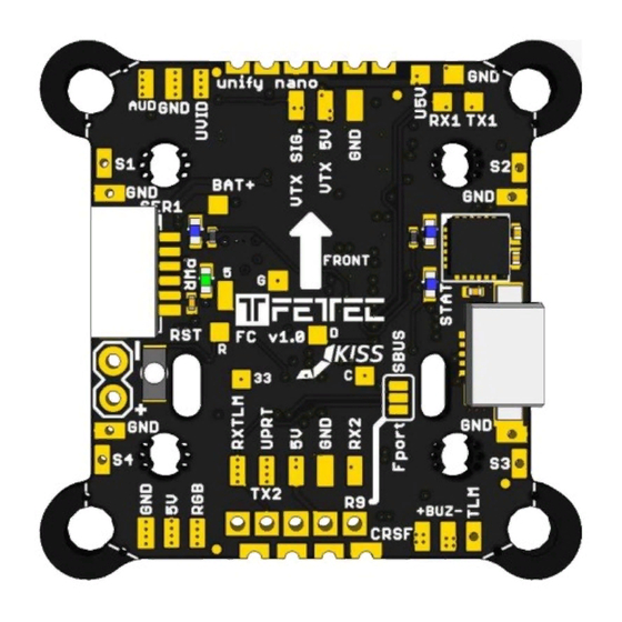
Page 4: Connection Diagram
Connection Diagram Top/Bottom Layout Signal1-4 – Motor Signal 1-4 ESCTLM – Telemetry (Serial) GND – Reference Signal Ground VPRT – Receiver signal port (SBUS / F-Port / PPM / Crossfire TX) RXTLM – Receiver telemetry (sPort / Crossfire RX) Serial connectors (SER1&SER3) are JST-SH-1mm 6-pin Page 4... -
Page 5: Dimension (In Mm)
Dimension (in mm) Dimensions 35x30mm without 30x30mm corners 20x20mm (with breakable holes M2 to M3) • 30x30mm hole distance useable (breakable 30x30mm corners) • Page 5... -
Page 6: Basic Setup
Basic Setup 8 pin connection (JST-SH-1mm 8-pin) FETtec KISS FC to FETtec ESC (cable included by FETtec ESC) Page 6... -
Page 7: Reciever Connection (Rx)
Reciever connection (RX) Top&Bottom connectors for recievers (bottom connector JST-SH-1mm 4-pin) FrSky R-XSR Page 7... -
Page 8: Crossfire Nano Connection
Crossfire nano connection cable connection 2,54mm pinheader connection VTX connection (unify nano) Page 8... -
Page 9: Camera Connection
Camera connection Notes: RX and TX connection is only for cameras that support serial • 5V (U5V) and Video (UVID) are only for use with a mounted unify PRO nano or unify • PRO nano 32 Resetbutton Resets the FC to the preflashed bootloader Page 9... -
Page 10: Kiss Firmware
KISS Firmware For the latest KISS FC firmware and GUI please visit https://github.com/flyduino To update the FETtec FC firmware please use the KISS GUI and choose FETTEC KISS FC Technical details - STM32F7RET6 @ 216MHz - MPU6000 - Supply voltage 6-27V (2-6S LiPo)
Need help?
Do you have a question about the KISS FC and is the answer not in the manual?
Questions and answers