
Related Manuals for Husqvarna 136LiHD50


Summary of Contents for Husqvarna 136LiHD50
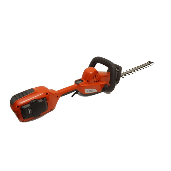
- Page 1 Workshop manual 136LiHD50, 536LiHD60X/520iHD60, English 536LiHD70X/520iHD70 456 - 002 - 03.10.2018...
-
Page 2: Table Of Contents
Contents 1 Introduction 7 Troubleshooting 1.1 Document description..........3 7.1 Overhaul...............29 1.2 Target group............3 7.2 To connect the common service tool....29 1.3 Revisions..............3 7.3 To do troubleshooting of the common service 1.4 Safety..............3 tool................29 1.5 Servicing tools............3 7.4 Troubleshooting of the product...... -
Page 3: Introduction
1.5 Servicing tools The manual gives information about necessary servicing tools. Always use original tools from Husqvarna. 456 - 002 - 03.10.2018 Introduction - 3... -
Page 4: Safety
2 Safety 2.1 Safety definitions WARNING: Do not put the battery back until the product is assembled. Warnings, cautions and notes are used to point out specially important parts of the manual. 1. Press in the catches (1) and remove the battery (2). WARNING: Used if there is a risk of injury or death for the operator or bystanders if the instructions in the manual are not obeyed. -
Page 5: Servicing Data
3 Servicing data 3.1 Servicing data 136 LiHD50 The numbers show the tightening torque for the component in Nm. ▲ Lubricate with chainsaw oil ● Lubricate with grease 1 Nm (x6) 2 ~ 3 Nm 4 mm 456 - 002 - 03.10.2018 Servicing data - 5... - Page 6 (x2) 2 ~ 3 Nm 4 mm (x2) 1 Nm (x8) 2 ~ 3 Nm 4 mm (x11) 2 ~ 3 Nm 4 mm 6 - Servicing data 456 - 002 - 03.10.2018...
-
Page 7: Servicing Data 536Lihd60X/520Ihd60, 536Lihd70X/520Ihd70
3.2 Servicing data 536LiHD60X/520iHD60, 536LiHD70X/520iHD70 LiHD60x US 8 mm (x2/x3(70X)) 2 ~ 3 Nm 4 mm (x5/x7(60X US)) 2 ~ 3 Nm 4 mm (x2) 2 ~ 3 Nm 4 mm (x6) 2 ~ 3 Nm 4 mm 456 - 002 - 03.10.2018 Servicing data - 7... - Page 8 (x4) 2 ~ 3 Nm 4 mm (x10) 2 ~ 3 Nm 4 mm (x2) 2 ~ 3 Nm 4 mm (x8) 2 ~ 3 Nm 4 mm (x4) 2 ~ 3 Nm 4 mm (x2) 1 Nm (x2) 1 Nm (x5) 2 ~ 3 Nm 4 mm 8 - Servicing data...
-
Page 9: Servicing Tools
4 Servicing tools 4.1 Diagnostic tool kit 4.1.1 Common service tool The common service tool (CST) tool is used with a COMMON computer (not included) for Husqvarna products. SERVICE TOOL INSTRUCTION The common service tool transmits data from the product and battery to the computer, for example product ID. -
Page 10: Repair Instructions 136 Lihd50
5 Repair instructions 136 LiHD50 5.1 To clean and examine the product parts 3. Remove the 11 screws and remove the right chassis half. • Clean and examine all parts fully. You find more instructions in the chapter for each part if special tools or procedures are necessary. - Page 11 3. Remove the 2 screws and remove the gears and the 5.4.2 To assemble the gear housing and the cutting unit from the gear housing. cutting unit Note: Always replace the gasket after you disassemble the gear housing. 1. Put the cutting unit on the hook (C). Attach the washer (B) and the circlip (A).
-
Page 12: Hand Guard
5.5 Hand guard 3. Remove the connector for the handle out of the chassis and disconnect it. Remove the handle from the product. 5.5.1 To disassemble the hand guard 1. Disassemble the wear guard, the front handle and the right chassis half. 2. -
Page 13: Motor And Gear Package
5.7.2 To assemble the power trigger 3. Connect the plug and put the gear housing and motor in the chassis. Make sure the cables from the 1. Put the power trigger (A), the catch (B) and the plug to the motor are put correctly in the chassis. spring (C) in their initial positions in the chassis. - Page 14 WARNING: Do not press the button on the main switch if it is not assembled in the handle. 1. Connect the keypad to the control unit. 2. Put the control unit, the cables with the main switch and the keypad into the chassis. Attach the battery plug with 2 screws.
-
Page 15: Repair Instructions 536Lihd60X/ 520Ihd60, 536Lihd70X/520Ihd70
6 Repair instructions 536LiHD60X/520iHD60, 536LiHD70X/ 520iHD70 6.1 To clean and examine the product parts 6.3 Cutting unit • Clean and examine all parts fully. You find more 6.3.1 To disassemble the cutting unit instructions in the chapter for each part if special tools or procedures are necessary. -
Page 16: Front Handle
1. Loosen the nut (A) that holds the connection plate 503 98 96-03 (20g). The gearbox must not be fully filled (B). with grease. • Apply approximately 2.5 g of grease. 2. Loosen the nuts (C). Note: For model 536LiHD60X/520iHD60 and 536LiHD70X/520iHD70 there are 5 nuts. - Page 17 1. Remove screw (A) and lift off the cover (B) above 4. Remove the 10 screws and carefully remove the the handle cables. handle half. 2. Remove the 3 screws that holds the handle. 5. Remove the relay with cables (C) and the loop (D) out of the handle.
-
Page 18: Power Trigger
1. Put the start inhibitor (E), plastic clips (F) and 5. Put the cables through the hole (B) in the chassis springs (G and H) in the handle. and connect the plugs (A) to the control unit. CAUTION: Make sure that the safety catch 2. -
Page 19: Gears
6.5.2 To assemble the power trigger 3. Remove the 2 screws that hold the gear housing and motor in the chassis. 1. Put the power trigger (C) into the handle. 4. Remove the gear housing and motor from the 2. Put the handle stop (A) and the spring (B) into the chassis. -
Page 20: Gear, Cutting Unit And Gear Housing
3. Connect the plug from the motor to the control unit. 6.7.2 To disassemble the gears Attach the plug with the gray cable in position (C). 1. Remove the circlip (A), remove the washer (B), carefully lift up the hook (C) and remove the cutting unit. -
Page 21: Control Unit And Battery Plug
6.8 Control unit and battery plug 1. Put the motor on the gear housing. 2. Put the gear and cutting unit in the gear housing. 6.8.1 To disassemble the control unit and Attach the cutting unit into the gear housing with 2 battery plug screws. -
Page 22: Keypad
1. Connect plugs (D and E) on the battery plug to the Disassemble the keypad if there is damage on the rear control unit. handle, the keypad or when troubleshooting indicates a defect. 1. To disconnect the plug (A), press the catch (B) and carefully pull the plug. -
Page 23: Main Switch And Main Cable
Do steps 1-3 only when you replace the keypad. 6. Put in the connector (A). 1. Clean the surface where the keypad is attached. 2. Make sure that the temperature is minimum 15°C. 6.10 Main switch and main cable Make sure that the temperature of the surface where the keypad is attached does not change more than ±3°C from the ambient temperature. - Page 24 4. To disconnect the cable, release the catch (D) with a 6.10.3 Assemble the main switch small srewdriver and pull the connection (C) out. 6.10.3.1 For products with S/N up to: 20180900383 1. Connect the connection (C) to the main switch. Apply grease to the contact surfaces and also the connector.
-
Page 25: Rear Handle
6.10.3.2 For products with S/N from: 20180900384 Note: Hold the parts in position in the handle when you 1. Connect cable (A) and make sure that the contact disassemble it. clicks into place. 1. Carefully lift out the cables, plug (A) and clips (B). Disconnect the plug. - Page 26 5. Use a screwdriver to carefully remove the fastener 9. Remove they keypad, the main switch and the from the handle. Then remove it from the cables cables from the handle. together with the O-ring. 6. Remove the 5 screws and remove the right handle 6.11.2 To assemble the rear handle half.
- Page 27 4. Put the cable through the O-ring and the fastener. Note: The fastener can only be pressed onto the handle Lubricate the O-ring lightly with grease to make the when the groove and the heel on the handle engage. assembly easier. Make sure that the O-ring is set correctly in the fastener.
- Page 28 8. Connect the plug (A) and put the cables with clips (B) in the chassis. 28 - Repair instructions 456 - 002 - 03.10.2018 536LiHD60X/520iHD60, 536LiHD70X/520iHD70...
-
Page 29: Troubleshooting
7 Troubleshooting 7.1 Overhaul Note: Refer to the manual for the common service tool for instructions and obey the instructions. Examine the components of the product. You find repair and servicing instructions for each component in the related chapters of this manual. 2. - Page 30 Symptom Possible causes Recommended step Changing motor speed. Defective connection in main switch Make sure that the keypad connector signal connector. is correctly assembled, dry, not dam- aged and that there is no corrosion. Damaged or worn main switch. Replace keypad. A warning sign on keypad flashes Temperature too high.
-
Page 31: Troubleshooting Of The Battery And Battery Charger
7.5 Troubleshooting of the battery and battery charger Symptom Possible causes Recommended step No LEDs flash on the battery when Defective battery. Replace the battery. you press the start button. A warning sign shows a constant red Defective battery. Replace the battery. light on the battery when the start but- ton is pressed. -
Page 32: Troubleshooting Of The Connectors
Symptom Possible causes Recommended step A green lamp on the charger comes Defective Battery. Put the battery in a QC330 charger. If on for approximately 5-10 seconds the same problem occurs, replace the when the battery is attached. After battery. that a red warning sign flashes on the Defective charger. -
Page 33: Troubleshooting Of The Electrical System
Measure between pin 2 and pin 5 when the switch is For products with S/N up to: 20180900383 not compressed. The result must be closed circuit. The main switch in battery products from Husqvarna • Measure between pin 2 and pin 5 when the switch is energizes the control unit and the motor. -
Page 34: Troubleshooting Of The Keypad
8.4 Troubleshooting the control unit PMDC - 136 LiHD50 Make sure that the blade terminals and related wires are not bent or damaged. (A) 6.3x0.8 mm M- (Black wire) (B) 6.3x0.8 mm M+ (Red wire) (C) 6.3x0.8 mm PCB + (Yellow wire) 1 2 3 4 5 6 (D) 6.3x0.8 mm PCB 0V (Black wire) (E) 4.8x0.8 mm Shutdown (Blue wire) -
Page 35: Troubleshooting Of The Battery Connector
8.6 Troubleshooting of the battery 4. Lift the plastic fastener and pull out the communication cable, if installed. connector 8.6.1 To disassemble the battery connector CAUTION: The pin in the connector of the communication cable is loose and can fall out. 1. - Page 36 8.6.2 To assemble the battery connector 3. Put the battery connector with the black wire into the negative side of the plastic housing. Align the holes CAUTION: The pin in the connector of the wire for the pins. is loose and can fall out. 1.
- Page 37 456 - 002 - 03.10.2018 Troubleshooting of the electrical system - 37...
- Page 38 38 - Troubleshooting of the electrical 456 - 002 - 03.10.2018 system...
- Page 39 456 - 002 - 03.10.2018 Troubleshooting of the electrical system - 39...
- Page 40 1157307-46 2018-11-02...