Advertisement
Quick Links
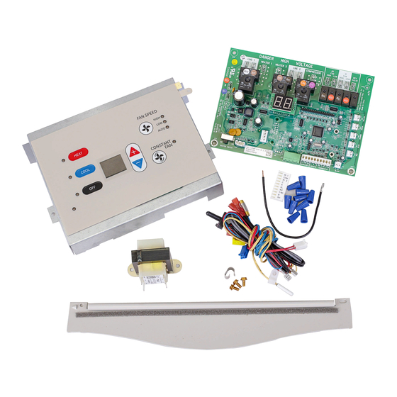
PTAC Control Board Kit RSKP0014
ATTENTION INSTALLING PERSONNEL
As a professional installer you have an obligation to know
the product better than the customer. This includes all safety
precautions and related items.
Prior to actual installation, thoroughly familiarize yourself with this
Instruction Manual. Pay special attention to all safety warnings.
Often during installation or repair it is possible to place yourself
in a position which is more hazardous than when the unit is in
operation.
Remember, it is your responsibility to install the product safely
and to know it well enough to be able to instruct a customer in its
safe use.
Safety is a matter of common sense...a matter of thinking before
acting. Most dealers have a list of specific good safety practices...
follow them.
The precautions listed in this Installation Manual are intended as
supplemental to existing practices. However, if there is a direct
conflict between existing practices and the content of this manual,
the precautions listed here take precedence.
RECOGNIZE THIS SYMBOL AS A SAFETY PRECAUTION
Only personnel that have been trained to install, adjust, service
or repair(hereinafter, "service") the equipment specified in this
manual should service the equipment. The manufacturer will not
be responsible for any injury or property damage arising from
improper service or service procedures. If you service this unit,
you assume responsibility for any injury or property damage
which may result. In addition, in jurisdictions that require one or
more licenses to service the equipment specified in this manual,
only licensed personnel should service the equipment.
Improper installation, adjustment, servicing or repair of the
equipment specified in this manual, or attempting to install,
adjust, service or repair the equipment specified in this manual
without proper training may result in product damage, property
damage, personal injury or death.
PROP 65 WARNING
FOR CALIFORNIA CONSUMERS
Cancer and Reproduc�ve Harm
www.P65Warnings.ca.gov
IO-905B
under license to Goodman Company, L.P., Houston, TX, USA. All rights reserved.
01/2020
Installation Instructions
WARNING
WARNING
-
19001 Kermier Rd., Waller, TX 77484
is a registered trademark of Maytag Corporation or its related companies and is used
© 2015 - 2016, 2020 Goodman Company, L.P.
DESCRIPTION
Control board installation procedures are described in detail in
these instructions. Read and follow these instructions carefully
before replacing the control board. Failure to do so may result in
control board damage.
Important note:
Damage to the control board can occur from failure to disconnect
power supply or failure to set the master switch (located on the
control board) to OFF before removing the low voltage terminal
strip cover from an installed control board. Damage to this board
by not following these instructions is considered misuse and not
covered under either the standard unit warranty or any extended
service contract.
Important note:
All warranty replaced boards must be returned to the parts source
from which they were purchased to insure proper warranty credit.
ELECTROSTATIC DISCHARGE (ESD)
PRECAUTIONS
Before removing the new control board from the static wrap, it
is very important to discharge any static electricity. Discharging
the static electricity can be accomplished by two methods: the
servicer can wear a ground strap or by touching the metal chassis
before replacing the board.
EXISTING BOARD REMOVAL PROCEDURE
1. Disconnect power to the unit by unplugging the power cord
at the wall outlet or subbase, or disconnect power at the fuse
box or circuit breaker.
0140M00517-A
www.amana-ptac.com
Advertisement

Related Manuals for Amana RSKP0014

Summary of Contents for Amana RSKP0014
- Page 1 PTAC Control Board Kit RSKP0014 Installation Instructions ATTENTION INSTALLING PERSONNEL DESCRIPTION As a professional installer you have an obligation to know Control board installation procedures are described in detail in the product better than the customer. This includes all safety these instructions.
- Page 2 NEW CONTROL BOARD INSTALLATION 2. If the cabinet front is screwed to the chassis, remove the 1/4” screw (or screws) located behind the inlet grille. Pull the inlet PROCEDURES grille forward from the top of the grille to access screw(s). 9.
- Page 3 A3. Replace the heater panel, routing the yellow wire around the right end of the heater panel and into the control panel pulling snug to prevent the wire from TR AN SFO R M ER being entangled in the blower wheel or being visible LINE from above.
- Page 4 17. The control board cover is now ready to be installed. The ribbon for the touch pad will need to be connected to the control board. Take caution not to bend or fold the ribbon. (See Figure 10 for ribbon connection). Ensure that no wires are pinched or caught between the cover and the panel and then reinstall the screws removed in Step 5.
- Page 5 CRITICAL STEP* will not operate This service control until it has been configured to control a heat pump or cooler. As long as the display shows , the unit will not operate Follow the directions on Pages 6 and 7 to set feature codes C3 and “dd”.
-
Page 6: Configuration Settings
REV. LINE 1 HIGH VALVE HIGH YELLOW Heat Pump models ONLY. Must not be used on PTC models. BLUE RIBBON CONNECTOR BLACK BLACK Left is ON Position Figure 10 INITIAL BOARD PROGRAMMING CONFIGURATION SETTINGS Press and continue to hold down the plus (+) and minus The control can be configured to operate a wide range (-) keys at the same time. - Page 7 CONFIGURATION SETTINGS CHART Configuration Configuration Feature Option Code Option Code Chassis Membrane * Interface Wired Thermostat Wireless Stat & 7-Button Locked Membrane do not use ID Fan Operation do not use Button present Revert to Cyclic Always run fan (even if Off) do not use Revert to Continuous PTC (Standard Cooler)
- Page 8 CONFIGURATION SETTINGS CHART (CONT.) Configuration Configuration Feature Option Code Option Code Smart Vent Operation On only when ID fan runs On when ID fan runs & room occupied Runs continuously On when room is occupied Economizer Economizer with compressor assist Vent Dehumid Make-up Air Kit Operation May be on anytime...
- Page 9 DIAGNOSTIC MAINTENANCE & STATUS REPORT The Diagnostic Maintenance & Status Report provides detailed information on PTAC control operation and operational status including present modes, failures, airflow restriction warnings, operating temperatures, and past failures. The lower right hand dot on the center display flashes in this mode.
-
Page 10: Diagnostic Codes
DIAGNOSTIC CODES ERROR CODE STATUS DISPLAY SUGGESTED ACTION LIGHT Freeze Protection Engaged. The room temperature No Action required. This setting will disengage when the measured by the wireless remote thermostat or indoor room temperature rises above 43°F. ambient thermistor active sensor falls below 40°F. Front Desk switch is closed. - Page 11 WIRING DIAGRAMS Single motor TRANS FO RM E R RD33 BR34 BR34 GY21 VT12 BK37 BK37 LINE 1 HEATER 1 HEATER 2 LINE 2 COMPRESSOR E5 E6 CR11 ON / OFF GL W2 Y/W1 B GL W2 Y/W1 B IN1 COM IN2 IN1 COM IN2 MASTER SWITCH BLACK...
- Page 12 WIRING DIAGRAMS Single Motor Power Vent Door HEATER 2 LINE 1 HEATER 1 LINE 2 CO MPRES S OR E5 E6 CR11 ON / OFF GL W2 Y/W1 B GL W2 Y/W1 B IN1 COM IN2 IN1 COM IN2 MAS TER S WITCH BLACK BLACK AUXILIARY...
- Page 13 WIRING DIAGRAMS Single Motor Condensate Pump HEATER 2 LINE 1 HEATER 1 LINE 2 C OMPRES SO R E5 E6 CR11 ON / OFF IN1 COM IN2 IN1 COM IN2 GL W2 Y/W1 B GL W2 Y/W1 B MASTER S WITCH BLACK BLACK AUXILIARY...
- Page 14 WIRING DIAGRAMS Dual Motor Wiring is subject to change. To MC TR 1 MOTOR MOTOR TR 1 TR 1 MOTOR MOTOR DANGER HIGH HEATER 1 HEATER 2 DANGER DANGER HIGH HIGH VOLTAGE VOLTAGE ALTERNATE REV. REV. LINE 1 LINE 1 HEATER 1 HEATER 1 HEATER 2...
- Page 15 WIRING DIAGRAMS Dual Motor (continued) > > > > ON/OFF SWITCH OPTIONAL DEHUMIDIFICATION OPTIONAL ELECTRIC HEATER > > OPTIONAL OPTIONAL TRANSFER LIGHTING CONTROL To MC To MC Outdoor Motor Speed Selection Indoor Motor Speed Selection High Speed Low Speed High Speed Low Speed Model Starts With VSTM Tap...
- Page 16 WIRING DIAGRAMS Dual Motor, 2 Speed Relay DUAL MOTOR, 2 SPEED RELAY * FOR A HEAT PUMP, THERMOSTAT USED REMOTE THERMOSTAT ON A STRAIGHT OPERATION COOL UNIT ** GL - LOW SPEED COOLING UNIT GH - HIGH SPEED RCCF W / ELECTRIC HEAT FUNCTION CONNECT R TO:...
- Page 17 WIRING DIAGRAMS Dual Motor No Speed Relay Single Speed Condenser Fan DUAL MOTOR, NO SPEED RELAY SINGLE SPEED CONDENSER FAN * FOR A HEAT PUMP, THERMOSTAT USED REMOTE THERMOSTAT ON A STRAIGHT OPERATION COOL UNIT ** GL - LOW SPEED COOLING UNIT GH - HIGH SPEED RCCF...
- Page 18 WIRING DIAGRAMS Dual Motor No Speed Relay Single Speed Condenser Fan 24VAC TRANSFORMER 12VA CLASS 2 ONLY LOAD...
- Page 19 WIRING DIAGRAMS Dual Motor No Speed Relay Single Speed Condenser Fan 24VAC TRANSFORMER 12VA CLASS 2 ONLY LOAD...
-
Page 20: Customer Feedback
Maytag Corporation or its related companies and is used under license to Goodman Company, L.P., Houston, TX, USA. All rights reserved. 19001 Kermier Rd. • Waller, TX 77484 • www.amana-ptac.com © 2015 - 2016, 2020 Goodman Company, L.P.
Need help?
Do you have a question about the RSKP0014 and is the answer not in the manual?
Questions and answers