Table of Contents
Advertisement
Quick Links
Advertisement
Table of Contents

Related Manuals for tousek PULL TSA


Summary of Contents for tousek PULL TSA
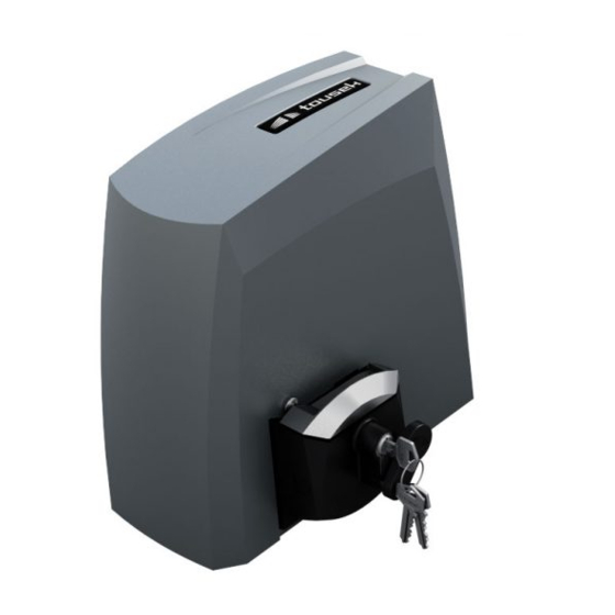
- Page 1 Mounting and istallation manual Sliding gate opener PULL TSA Safety Sensor...
-
Page 2: Table Of Contents
Declaration of incorporation and conformity ................... 27 This manual is the sole property of the TOUSEK Ges.m.b.H. and may not be made available to competitors. All rights reserved. No part of it may be reproduced without our prior written permission. We will not accept liability for any claims resulting from misprints or errors. This edition of the manual replaces all earlier publications of the same. -
Page 3: General Warning And Safety Details
EU and in the individual countries have to be strictly followed. • The TOUSEK Ges.m.b.H. cannot be held liable for any claims resulting from disregards of the laws and standards in force during the installation and operation. -
Page 4: Features, General, Function, Techncal Data
You can install the PULL TSA on new or already exsting sliding gates in a simple and fast way. -
Page 5: Installation
• Attention: Mechanial limit stops are absolutely necessary! • Attention: The sliding gate operator PULL TSA ias been developed and designed for the automation of hori- zontally travelling sliding gates. Gates on sloping tracks (i.e. gates which follow an inclined, non-horizontal, travel path) must not be automated without additional safety devices (which make sure that the gate cannot start moving on its own from any gate position). -
Page 6: Installation Of The Motor
Z20M4: r44 optional half-profile cylinder gear wheel cable exit ground plate (4a) slotted holes (4x) for connection on the ground steel gear rack 124,1 Foundation 39,3 - 6 - tousek / EN_PULL-TSA_03 / 25. 03. 2020... -
Page 7: Installation Of Teh Gear Rack
Attention • Do not weld the individual gear rack elements together! 2.3 Dismantling The dismantling of motor is made the other way around of mounting. Before dismantling please plug off power supply of motor ! - 7 - tousek / EN_PULL-TSA_03 / 25. 03. 2020... -
Page 8: Control Board, Layout Of The Control Board
Terminal blocks Sensor plug (on the back side) (KM) Motor clamps (7S) 7-Segment display (FE) Integrated radio receiver (TA) Programming buttons (+, -, ESC und ENTER) Antenna plug Fuse 3,15A T - 8 - tousek / EN_PULL-TSA_03 / 25. 03. 2020... -
Page 9: Warning Notes - Connection Works
The stop input has no emergency stop function! - In order to ensure the emergency stop function, provide the supply line with an all-pole disconnecting emergency stop switch, that locks after actuation! - 9 - tousek / EN_PULL-TSA_03 / 25. 03. 2020... -
Page 10: Adjustments - Overview, Programming Buttons
(without saving the changed parameters). The selectable parameters of the menu items are marked in the table below as follows: = selectable settings (value assignment possible) = factory settings - 10 - tousek / EN_PULL-TSA_03 / 25. 03. 2020... -
Page 11: Stucture Of The Menu
Note: some adjustments regarding function or operating logic can only be executed if the gate is closed and the display shows the status „ready for operation“. ENTER integrated control for slider PULL TSA - 11 - tousek / EN_PULL-TSA_03 / 25. 03. 2020... -
Page 12: Connections And Adjustments
With confirmation by the ENTER button of the remote control in question is completely extinguished, ie all programmed keys of the remote control. delete all: NO: do not delete the transmitters. YES: all the programmed remote controls get deleted after confirming with Enter. - 12 - tousek / EN_PULL-TSA_03 / 25. 03. 2020... -
Page 13: Mounting Direction
• IMPORTANT: do not carry out commissioning in dead man modus. If desired, select this func- tion only after commissioning (see page 20). Pushbuttons, key switches as well as external radio receivers with potential free make contacts can be used as impulse emitters. - 13 - tousek / EN_PULL-TSA_03 / 25. 03. 2020... -
Page 14: Pedestrian Button, Stop-Contact
The stop input has no emergency stop function! - In order to ensure the emergency stop function, provide the supply line with an all-pole disconnecting emergency stop switch, that locks after actuation! - 14 - tousek / EN_PULL-TSA_03 / 25. 03. 2020... -
Page 15: Photocells
Photocells - connection examples Tousek Photocell LS 180 Transmitter Receiver as safety device Important At the control of the PULL TSA can be connected only one photocell LS 180 (included in the kit). - 15 - tousek / EN_PULL-TSA_03 / 25. 03. 2020... -
Page 16: Safety Edges ( Mse-Main , Ssf- Side Safety Edge)
0–9 adjustable: defines the max. permissible motor force – (0 =min., 9 = max.) Important • The motor stops when max. set force is exceeded. • WARNING: The safety regulations about the force settings must be observed! - 16 - tousek / EN_PULL-TSA_03 / 25. 03. 2020... -
Page 17: Ars Response Time
9, which means a reduction of approx 200mm for both final positions This adjustment is ONLY adopted when the gate is CLOSED. - 17 - tousek / EN_PULL-TSA_03 / 25. 03. 2020... -
Page 18: Reset & Diagnosis
• The photocell test can be suppressed by selecting „not active“. • The deactivation of the self-test function is only permitted if the safety equipment correspond to the category 3. - 18 - tousek / EN_PULL-TSA_03 / 25. 03. 2020... -
Page 19: Emergency Release In Case Of Power Failure (Note For The User)
• Remove the protective cap and secure the cilinder with the screw (S). Then replace the protective cap. • To re-insert the cylinder please carry out the above steps in the reverse order. - 19 - tousek / EN_PULL-TSA_03 / 25. 03. 2020... -
Page 20: Commisioning
Mounting direction settings Setting of the change? YES parameters Impulse button Setting of the change? YES parameters End position H 8 H 9 ready for operation detecting detecting open-position closed-poition - 20 - tousek / EN_PULL-TSA_03 / 25. 03. 2020... -
Page 21: Status Dispaly
Sliding gate opener PULL TSA Display Meanng detect end position open ready gate closed gate opens gate stopped gate open gate partial opening gate closes detect open position detect closed position - 21 - tousek / EN_PULL-TSA_03 / 25. 03. 2020... -
Page 22: Troubleshooting Guide
Control relays are switching but no motor released lock motor gearing gate movement - 22 - tousek / EN_PULL-TSA_03 / 25. 03. 2020... - Page 23 - 23 - tousek / EN_PULL-TSA_03 / 25. 03. 2020...
-
Page 24: Cable Plan
- 24 - tousek / EN_PULL-TSA_03 / 25. 03. 2020... -
Page 25: Dimensioned Drawing
3 keys (art. code13300220) 124,1 View B: View A: gear wheel Z20M4: r44 270,8 146,5 39,3 We reserve the right to change dimensions and technical specifications without prior notice. - 25 - tousek / EN_PULL-TSA_03 / 25. 03. 2020... -
Page 26: List Of The Transmitter
11. List of the transmitter Sliding gate opener PULL TSA Memory memory Transmitter Transmitter position position - 26 - tousek / EN_PULL-TSA_03 / 25. 03. 2020... -
Page 27: Declaration Of Incorporation And Conformity
Date/ Signature TOUSEK Ges.m.b.H., A1230 Wien, Zetschegasse 1, Österreich is authorized to compile the technical documentation. The incomplete machine cannot be put into service, until it... - Page 28 Buitenheide 2A/ 1 Tel. +32/ 11/ 91 61 60 your service partner: Fax +32/ 11/ 96 87 05 info@tousek.be Tousek Sp. z o.o. Poland PL 43-190 Mikołów (k/Katowic) Gliwicka 67 Tel. +48/ 32/ 738 53 65 Fax +48/ 32/ 738 53 66 info@tousek.pl...
Need help?
Do you have a question about the PULL TSA and is the answer not in the manual?
Questions and answers