Advertisement
Quick Links
3042650 Steel Frame
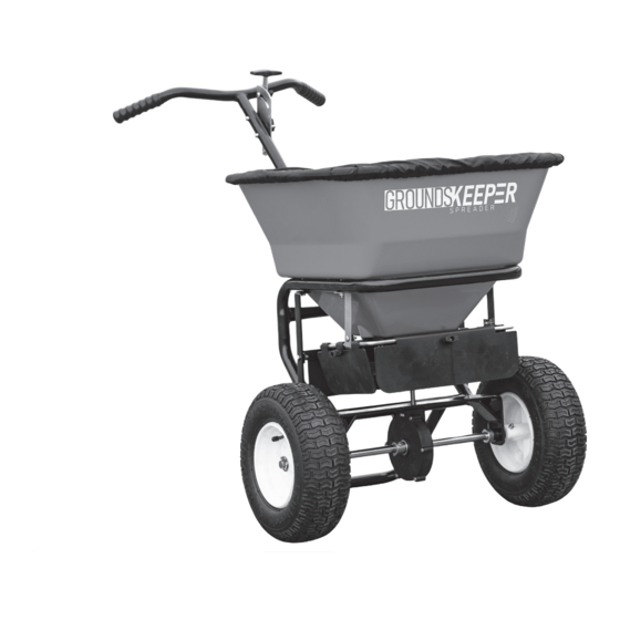
Walk Behind Broadcast Spreader
Manufacturer will repair, or at manufacturer's discretion will replace any part of this salt spreader which proves to be defective in workmanship or material
under normal use for a period of one year from the date of delivery to the original purchaser. Any cost incurred in returning the product to the supplier is the
responsibility of the consumer.
Manufacturer shall not be liable for special, incidental, or consequential damages, or for damages resulting from lack of necessary maintenance, from misuse,
abuse, acts of God, or alteration of the product. Some states do not allow the exclusion or limitation of incidental or consequential damages, so the above
limitation or exclusion may not apply to you.
Assembly Instructions
FULL ONE YEAR WARRANTY
EXCLUSIONS
1
9049 Tyler Blvd. • Mentor, Ohio 44060
Phone (440) 974-8888 • Fax (800) 841-8003
www.buyersproducts.com
Advertisement

Summary of Contents for GroundsKeeper 3042650
- Page 1 Phone (440) 974-8888 • Fax (800) 841-8003 www.buyersproducts.com Assembly Instructions 3042650 Steel Frame Walk Behind Broadcast Spreader FULL ONE YEAR WARRANTY Manufacturer will repair, or at manufacturer’s discretion will replace any part of this salt spreader which proves to be defective in workmanship or material under normal use for a period of one year from the date of delivery to the original purchaser.
- Page 2 Rear Deflector Assembly Rain Cover And Hardware Kit Are Not Shown C. Carefully insert the Lower Linkage into the Restrictor Plate Figure 3 underneath the Hopper as shown. (The Lower Linkage has two TOOLS NEEDED FOR ASSEMBLY Figure 1 - Contents of Box Figure 2 bent ends &...
- Page 3 Step E Attach Control Plate Assembly To Frame Using M6x40 Bolts F. Attach Control Handle G. Remove Control Assembly to Frame Handle from Assembly, Using M6x40 Bolts Rod To Be Flat (Parallel Insert Upper Linkage Step E To The Ground) into Control Handle, Reattach Control Handle Attach Control Plate Assembly...
- Page 4 9049 Tyler Blvd. • Mentor, Ohio 44060 Phone (440) 974-8888 • Fax (800) 841-8003 www.buyersproducts.com Parts List Bill of Material ITEM PART NO. DESCRIPTION ITEM PART NO. DESCRIPTION 3021435 Frame 3010878 Linkage Plate Assembly 3010874 Handle 3010879 Lower Linkage 3042704 Hopper Assembly 3010880 Upper Linkage...
Need help?
Do you have a question about the 3042650 and is the answer not in the manual?
Questions and answers