Advertisement
Quick Links
thank you for purchasing a Sealey product. manufactured to a high standard, this product will, if used according to these instructions,
and properly maintained, give you years of trouble free performance.
IMPORTANT: PLEASE READ THESE INSTRUCTIONS CAREFULLY. NOTE THE SAFE OPERATIONAL REQUIREMENTS, WARNINGS & CAUTIONS. USE
THE PRODUCT CORRECTLY AND WITH CARE FOR THE PURPOSE FOR WHICH IT IS INTENDED. FAILURE TO DO SO MAY CAUSE DAMAGE AND/OR
PERSONAL INJURY AND WILL INVALIDATE THE WARRANTY. KEEP THESE INSTRUCTIONS SAFE FOR FUTURE USE.
Refer to
Warning!
instruction
electricity
manual
1. SAfety
WArNiNG! To avoid possible electric shock or personal injury, follow these guidelines:
‰
dO NOt use the meter if it is damaged. Before you use the meter, inspect the case. Pay particular attention to the insulation
8
surrounding the connectors.
Inspect the test leads for damaged insulation or exposed metal. Check the test leads for continuity. Replace damaged test leads
9
before using the meter.
dO NOt use the meter if it operates abnormally. Protection may be impaired. When in doubt, have the meter serviced.
8
dO NOt operate the meter around explosive gas, vapour, or dust. don't use it under wet conditions.
8
dO NOt apply more than the rated voltage, marked on the meter, between terminals or between any terminal and earth ground.
8
Before use, verify the meter's operation by measuring a known voltage.
9
Use caution when working with voltage above 30V ac rms, 42V peak, or 60V dc. Such voltages pose a shock hazard.
9
When using the probes, keep your fingers behind the finger guards on the probes.
9
Connect the common test lead before you connect the live test lead. When you disconnect test leads, disconnect the live test lead first.
9
Remove the test leads from the meter and remove the clamp jaws from the conductor under test before opening the case or the
9
battery cover.
dO NOt operate with the battery cover or portions of the case removed or loosened.
8
To avoid false readings,which could lead to possible, electric shock or personal Injury, replace the batteries as soon as the low battery
9
indicator
To avoid electric shock, dO NOt touch any naked conductor with hand or skin.
9
dO NOt hold the meter anywhere beyond the finger guard.
8
Adhere to local and national safety codes. Individual protective equipment must be used to prevent shock and arc blast injury where
9
hazardous live conductors are exposed.
dO NOt use the test leads with other equipment.
8
WArNiNG: When an input terminal is connected to dangerous live potential, this potential can occur at all other terminals!
‰
CAt ill - measurement (Category Ill is for measurements performed in building installation.)
examples are measurements on distribution boards, circuit breakers, wiring, including cables, bus-bars, junction boxes, switches,
socket-outlets in the fixed installation, and equipment for industrial use and some other equipment, for example, stationary motors with
permanent connection to fixed installation.
dO NOt use the meter for measurements within measurement Categories IV.
8
WArNiNG! To avoid possible damage to the meter or to the equipment under test, follow these guidelines:
‰
disconnect circuit power and discharge all capacitors before testing resistance, diode and continuity.
9
Use the proper function and range for your measurements.
9
Before rotating the function switch to change functions, remove test leads from the circuit under test and remove the jaws from the
9
clamped conductor.
2.
iNtrOduCtiON
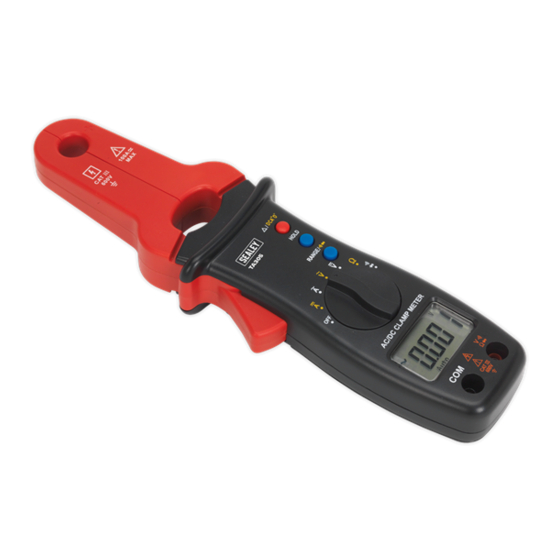
designed for the automotive electrician and conforms to eN61010 CAt iii 600V. Ideal for measuring current draw from vehicle components in
situ. Features 12mm clamp. Supplied in pouch.
measures:
AC and dC voltage
AC and dC current
Resistance
Audible continuity
diode test
© Jack Sealey limited
AC/dC ClAmp meter & multimeter
model no:
appears.
Original Language Version
tA305
TA305 Issue 3 (3) - 12/12/18
Advertisement

Related Manuals for Sealey TA305


Summary of Contents for Sealey TA305
- Page 1 Sealey product. manufactured to a high standard, this product will, if used according to these instructions, and properly maintained, give you years of trouble free performance. IMPORTANT: PLEASE READ THESE INSTRUCTIONS CAREFULLY. NOTE THE SAFE OPERATIONAL REQUIREMENTS, WARNINGS & CAUTIONS. USE THE PRODUCT CORRECTLY AND WITH CARE FOR THE PURPOSE FOR WHICH IT IS INTENDED.
-
Page 2: Specification
........AC100A Response: ....Average, calibrated in rms of sine wave Temperature coefficient: ......±0.3% of reading/°C dC current max. allowable input current: ........dC100A Temperature coefficient: ......±0.3% of reading/°C TA305 Issue 3 (3) - 12/12/18 Original Language Version © Jack Sealey limited... - Page 3 Buzzer sounds if a button is pressed. Before the meter turns off automatically, the meter will emit 5 short beeps, 1 minute later it will emit a long beep then turn off automatically. TA305 Issue 3 (3) - 12/12/18 Original Language Version © Jack Sealey limited...
-
Page 4: Operation
(iii) The meter’s measuring capacity is 100A. measuring a current higher than 100A will cause a larger measurement error. (iv) dO NOt use the meter to measure a circuit’s current if the voltage exceeds 600V. Original Language Version © Jack Sealey limited TA305 Issue 3 (3) - 12/12/18... -
Page 5: Maintenance
BAttery remOVAl; See SeCtiON6.3 ABOVe Under the Waste Batteries and Accumulators Regulations 2009, Jack Sealey ltd are required to inform potential purchasers of products containing batteries (as defined within these regulations), that they are registered with Valpak’s registered compliance scheme.