Table of Contents
Advertisement
Quick Links
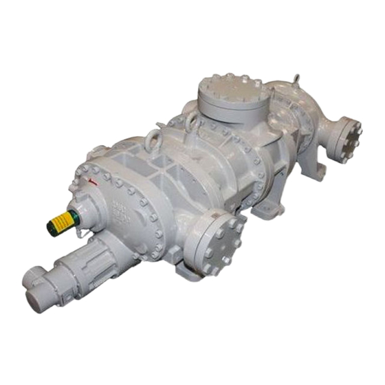
Compound 2-stage Screw
Compressor
2016**C Instruction Manual
Before operating, servicing, or inspecting this product, read this manual thoroughly to
fully understand the contents.
Keep this Instruction Manual in a safe, designated place for future reference whenever
the manual is needed.
Specifications of this product is subject to change without prior notice.
2016LLC / 2016LMC / 2016LSC
/ 2016MSC / 2016SSC
ATTENTION
2200LZJE-HO-C6-N_2013.12.
Advertisement
Table of Contents

Related Manuals for mycom 2016 C Series


Summary of Contents for mycom 2016 C Series
- Page 1 2200LZJE-HO-C6-N_2013.12. Compound 2-stage Screw Compressor 2016**C Instruction Manual 2016LLC / 2016LMC / 2016LSC / 2016MSC / 2016SSC ATTENTION Before operating, servicing, or inspecting this product, read this manual thoroughly to fully understand the contents. Keep this Instruction Manual in a safe, designated place for future reference whenever the manual is needed.
- Page 2 2200LZJE-HO-C6-N_2013.12. Preface Preface Thank you for purchasing the compound 2-stage screw compressor 2016**C (hereinafter referred to as "this product"). This Instruction Manual (hereinafter referred to as "this manual") provides safety information and operation and maintenance procedures, so that users correctly understand how to handle this product and, as a result, can use it safely and efficiently.
- Page 3 2200LZJE-HO-C6-N_2013.12. Warranty and Disclaimer Warranty and Disclaimer Warranty Clauses Mayekawa shall repair or replace parts of this product for no charge if any failure resulting from defects in design or manufacture occurs, under normal use with the purpose and method that are in accordance with the specifications of this product and this manual, within the warranty period.
- Page 4 2200LZJE-HO-C6-N_2013.12. Important Information Important Information Intended Use of This Product This product is a general-purpose screw compressor for refrigeration and cold storage. Do not use this product for any other purposes that are not intended for or which depart from the specifications. For specifications of this product, refer to "2.3 Compressor Specifications".
- Page 5 2200LZJE-HO-C6-N_2013.12. Important Information Observe the following precautions when performing maintenance work on electrical control. Electrical maintenance of the product must be performed by certified/qualified personnel and only those educated about the electrical control of the product. Before servicing or inspecting the electrical equipment or devices, turn "OFF" the motor main power and control power, and perform lockout/tagout to prevent the power from being turned on during work.
-
Page 6: Table Of Contents
2200LZJE-HO-C6-N_2013.12. Table of Contents Table of Contents Preface ........................ⅰ Revision History ..................... ⅰ Warranty and Disclaimer ..................ⅱ Important Information .................... ⅲ Intended Use of This Product ................... ⅲ Important Information for Safe Use of This Product ............ⅲ About This Manual ...................... - Page 7 2200LZJE-HO-C6-N_2013.12. Table of Contents Configuration of Compressor ..............2-9 2.4.1 Sectional View ..................... 2-9 Mechanisms ....................2-10 2.5.1 Basics of the Screw Compressor ..............2-10 2.5.2 Suction Process ....................2-10 2.5.3 Compression Process ..................2-11 2.5.4 Discharge Process ..................... 2-11 2.5.5 About Volume Ratio (Vi) ..................
- Page 8 2200LZJE-HO-C6-N_2013.12. Table of Contents Chapter 5 Maintenance Precautions for Maintenance ..............5-1 Maintenance List ..................5-2 5.2.1 Daily Management ....................5-2 5.2.2 Periodical Inspection .................... 5-4 5.2.3 Guidelines for Compressor Overhaul Frequency ..........5-4 Management of Lubricant ................5-6 5.3.1 Lubricant Management Criteria ................
- Page 9 2200LZJE-HO-C6-N_2013.12. Table of Contents 5.6.11 High-stage Suction Cover and Side Bearings ........... 5-30 5.6.11.1 Disassembly ....................5-30 5.6.11.2 Inspection ....................5-30 5.6.12 Pulling out High-stage Rotor ................5-31 5.6.12.1 Disassembly ....................5-31 5.6.12.2 Inspection ....................5-32 5.6.13 High-stage Bearing Head and Main Bearings ........... 5-33 5.6.13.1 Disassembly ....................
- Page 10 2200LZJE-HO-C6-N_2013.12. Table of Contents Chapter 6 Troubleshooting Table 6-1 Troubleshooting ................... 6-1 Chapter 7 Related Documents Development Views, Assembly Sectional Views ........7-1 Figure 7-1 2016C Development View (Low-stage Side) ........7-1 Figure 7-2 2016C Development View (High-stage Side) ........7-2 ...
-
Page 11: Chapter 1 Safety
2200LZJE-HO-C6-N_2013.12. Chapter 1 Safety Chapter 1 Safety Observation/Prevention (DOs and DON'Ts) 1.1.1 1.1.1.1 DOs on Operation Make sure to attach safety and protective devices on the unit. Regularly inspect the safety and protective devices if they function properly. ... -
Page 12: Dos About Personal Protective Gear
2200LZJE-HO-C6-N_2013.12. Chapter 1 Safety In the following situations, workers may neglect to perform power source shutoff or lockout/tagout. Clearly notify the workers of the necessity of lockout/tagout. It is assumed that workers do not perform lockout/tagout before starting work because it is troublesome, and only turn "OFF"... -
Page 13: Warnings
2200LZJE-HO-C6-N_2013.12. Chapter 1 Safety Warnings The following two measures are taken for this product to let workers pay attention to possible dangers. Warnings described in this manual Safety labels affixed on the product main body * No safety labels are affixed to the compressor itself which this manual is intended for. For details about the warning labels affixed to the unit, refer to the instruction manual of the unit. -
Page 14: Residual Risks
2200LZJE-HO-C6-N_2013.12. Chapter 1 Safety Residual Risks The following information assumes that this product is operated or inspected/maintained while being used in general refrigerating/cold storage units. It is impossible to predict all the risk sources involved in actual use of the refrigerating/cold storage units. Devise appropriate countermeasures for hazardous sources in your systems. - Page 15 2200LZJE-HO-C6-N_2013.12. Chapter 1 Safety Figure 1-1 Locations of Hazardous Sources (compressor) Photo 001 Locations of Hazardous Sources Compound 2-stage Screw Compressor 2016**C 1.3 Residual Risks...
-
Page 16: Safety Devices
2200LZJE-HO-C6-N_2013.12. Chapter 1 Safety Safety Devices For safe use and protection of this product, make sure to attach safety devices to this product in accordance with the regulations and the following instructions. Safety devices cannot be kept in normal condition unless inspected and maintained at regular intervals. Their maintenance and inspection need to be performed as an important part of the maintenance/inspection work project. -
Page 17: Compressor Protective Devices
2200LZJE-HO-C6-N_2013.12. Chapter 1 Safety 1.4.3 Compressor Protective Devices Be sure to adjust the set values and check operation of the protective devices at the test run. Overview/Function/Purpose These protective devices are used to protect this product. Protecting from discharge temperature rise (DT) This device stops the compressor operation when the discharge temperature of the compressor exceeds the set value. - Page 18 2200LZJE-HO-C6-N_2013.12. Chapter 1 Safety Connection Positions and Settings For connection position and setting for each compressor protective device, refer to the instruction manual of the unit. Make sure that the set values do not exceed the operating limits shown in Chapter 2, section 2.3.2 and Table 2-2 of this manual.
-
Page 19: Chapter 2 Configuration And Specifications Of Compressor
2200LZJE-HO-C6-N_2013.12. Chapter 2 Configuration and Specifications of Compressor Chapter 2 Configuration and Specifications of Compressor Features of the Compound 2-stage Screw Compressor 2016**C The 2-stage compression system, which has hitherto required two units of standard-type screw compressor for its embodiment, can now be realized by a single unit of compound 2-stage screw compressor. -
Page 20: Compressor Specifications
2200LZJE-HO-C6-N_2013.12. Chapter 2 Configuration and Specifications of Compressor Compressor Specifications 2.3.1 Specifications Table 2-1 2016**C Screw Compressor Specifications 2016 Items Weight 1180 1140 1100 1050 1000 Low-stage theoretical displacement 1460/1210 1460/1210 1460/1210 1220/1020 975/810 @3550 rpm /2950 rpm High-stage theoretical displacement 749/622 624/519... -
Page 21: Operation Limits
2200LZJE-HO-C6-N_2013.12. Chapter 2 Configuration and Specifications of Compressor 2.3.2 Operation Limits Table 2-2 Operation Limits of 2016**C Items Operation Limits Remarks Maximum discharge pressure 1.96 MPa *Note 1 Casing design pressure: 2.6 MPa Minimum suction pressure -0.080 MPa Shaft seal, inherent properties Maximum intermediate 0.588 MPa Bearing... - Page 22 2200LZJE-HO-C6-N_2013.12. Chapter 2 Configuration and Specifications of Compressor 2.3.3 Outer Dimensions Figure 2-1 Outer Dimensions 2016LLC Compound 2-stage Screw Compressor 2016**C 2.3 Compressor Specifications...
- Page 23 2200LZJE-HO-C6-N_2013.12. Chapter 2 Configuration and Specifications of Compressor Figure 2-2 Outer Dimensions 2016LMC Compound 2-stage Screw Compressor 2016**C 2.3 Compressor Specifications...
- Page 24 2200LZJE-HO-C6-N_2013.12. Chapter 2 Configuration and Specifications of Compressor Figure 2-3 Outer Dimensions 2016LSC Compound 2-stage Screw Compressor 2016**C 2.3 Compressor Specifications...
- Page 25 2200LZJE-HO-C6-N_2013.12. Chapter 2 Configuration and Specifications of Compressor Figure 2-4 Outer Dimensions 2016MSC Compound 2-stage Screw Compressor 2016**C 2.3 Compressor Specifications...
- Page 26 2200LZJE-HO-C6-N_2013.12. Chapter 2 Configuration and Specifications of Compressor Figure 2-5 Outer Dimensions 2016SSC Compound 2-stage Screw Compressor 2016**C 2.3 Compressor Specifications...
-
Page 27: Configuration Of Compressor
2200LZJE-HO-C6-N_2013.12. Chapter 2 Configuration and Specifications of Compressor Configuration of Compressor For names of each part of the compressor, refer to "7.1 Development Views, Assembly Sectional Views ", and "7.2 Parts Configuration Table". 2.4.1 Sectional View Suction port High-stage capacity control mechanism Low-stage capacity control... -
Page 28: Mechanisms
2200LZJE-HO-C6-N_2013.12. Chapter 2 Configuration and Specifications of Compressor Mechanisms 2.5.1 Basics of the Screw Compressor The screw compressor is categorized as a positive displacement rotary compressor. It has features of both reciprocating and centrifugal compressors. As shown in Figure 2-7, the refrigerant (gas) is continuously compressed by the 3-dimensional spaces that are formed by a pair of male and female screw rotors (with different sectional profiles) and the casing, as the spaces change continuously. -
Page 29: Compression Process
2200LZJE-HO-C6-N_2013.12. Chapter 2 Configuration and Specifications of Compressor 2.5.3 Compression Process As the rotors rotate further, the volume between the rotor teeth and grooves decreases while the sealing line moves toward the discharge side, which compresses the trapped refrigerant gas. Figure 2-9 Compression Process Figure 2-10 Discharge Process 2.5.4... - Page 30 2200LZJE-HO-C6-N_2013.12. Chapter 2 Configuration and Specifications of Compressor (A) Properly adapted Vi to load condition Both the required compression ratio and Vi are low. Both the required compression ratio and Vi are high. Suction Discharge Compression Discharge Suction Compression Suction port closed Suction port closed Discharge port...
-
Page 31: Capacity Control Mechanism
2200LZJE-HO-C6-N_2013.12. Chapter 2 Configuration and Specifications of Compressor 2.5.6 Capacity Control Mechanism The capacity control mechanism, by moving a slide valve, lets suction gas (immediately before compressed) bypass and advance to the suction side, to help shorten the rotor portion used for compression. -
Page 32: Gas And Oil Flow
2200LZJE-HO-C6-N_2013.12. Chapter 2 Configuration and Specifications of Compressor Gas and Oil Flow The compression process of the screw compressor is as described in the preceding paragraphs. Gas of the compound 2-stage screw compressor 2016**C is sent from the evaporator, and passes through the strainer and check valve. -
Page 33: Chapter 3 Installation
2200LZJE-HO-C6-N_2013.12. Chapter 3 Installation Chapter 3 Installation General Precautions for Installation This chapter (Installation) assumes that the compressor is installed to a standard refrigeration / cold storage unit. If the unit you are actually using is not the standard type refrigeration/cold storage unit, prepare a proper installation manual by referring to the description in this chapter and paying due consideration to safety, before installing the compressor. - Page 34 2200LZJE-HO-C6-N_2013.12. Chapter 3 Installation The compressor eye bolts must not be used for lifting the unit. To lift the unit, use the lifting chains provided around the base or other lifting means provided on the base. Check path of compressor installation to make sure it is free of obstacles in consideration of the compressor size.
- Page 35 2200LZJE-HO-C6-N_2013.12. Chapter 3 Installation Outer Dimensions, Weight and Lifting Position 2016LLC 2016LMC 2016LSC 2016MSC 2016SSC Weight (kg) 1180 1140 1100 1050 1000 (mm) 1980.5 1913.5 1842.5 1787.5 1730.5 Figure 3-1 Outer Dimensions, Weight and Lifting Position of Compressor Photo 002 Lifting Position Compound 2-stage Screw Compressor 2016**C 3.2 Installation Works...
-
Page 36: Preparation For Installation
2200LZJE-HO-C6-N_2013.12. Chapter 3 Installation 3.2.4 Preparation for Installation Installation Space Secure sufficient working space for easy operation, cleaning, maintenance, and inspection. Illumination Prepare illumination devices which allow easy operation, cleaning, maintenance, and inspection. Ventilation If natural ventilation is insufficient, install ventilation fans according to the relevant regulations. ... -
Page 37: Installation
2200LZJE-HO-C6-N_2013.12. Chapter 3 Installation 3.2.5 Installation 3.2.5.1 Installation Check that the surface of the refrigeration/cold storage unit, where the compressor is to be installed, is even and horizontal. If it is uneven and non-horizontal, tightening the bolts may lead to compressor deformation, which may prevent normal operation. -
Page 38: Airtightness Test
2200LZJE-HO-C6-N_2013.12. Chapter 3 Installation Compressor Protective Devices (Safety Devices) To protect the compressor, install the protective devices as indicated in "1.4.3 Compressor Protective Devices" in this manual. 3.2.6 Airtightness Test Perform an airtightness test on the refrigerating/cold storage unit. 3.2.7 Lubricant Charge ... -
Page 39: Additional Charge Of Lubricant
2200LZJE-HO-C6-N_2013.12. Chapter 3 Installation Be sure to conduct the initial charge of lubricant in such a way that the oil cooler and oil filter are filled with lubricant. For details about lubricant to be used, see "4.1 Lubricant (Refrigerant Oil)" in this manual. ... -
Page 40: Chapter 4 Operation Of Compressor And Unit
2200LZJE-HO-C6-N_2013.12. Chapter 4 Operation of Compressor and Unit Chapter 4 Operation of Compressor and Unit Lubricant (Refrigerant Oil) Lubrication management is very significant to keep the compressor in a good operating condition. Take the following notes when managing lubricant. 4.1.1 Precautions for Selecting the Lubricant ... -
Page 41: Oils For Systems Using Hfc Refrigerants
2200LZJE-HO-C6-N_2013.12. Chapter 4 Operation of Compressor and Unit Mineral oils (non-inter-soluble oils) Kinematic viscosity Brand Manufacturer Type (40°C) mm SUNISO 3GS Sun Oil Naphthene base SUNISO 4GS Sun Oil REFOIL NS 3GS Nippon Oil GARGOYLE ARCTIC C HEAVY Exxon Mobil GARGOYLE ARCTIC 300 Exxon Mobil CAPELLA WF46... -
Page 42: Change Of Lubricant Brand
2200LZJE-HO-C6-N_2013.12. Chapter 4 Operation of Compressor and Unit Polyolester Synthetic Oil (POE) for R134a: Inter-soluble synthetic oil Kinematic viscosity Brand Manufacturer Type (40°C) mm JOMO Freol α100 JX Nippon Oil and Energy Corporation When using lubricant of a brand not described in this section, or when using lubricant along with refrigerants or gases not described in this section, please contact us. -
Page 43: Precautions For Handling Jomo Freol Pn46 (Ammonia-Inter-Soluble Oil)
2200LZJE-HO-C6-N_2013.12. Chapter 4 Operation of Compressor and Unit 4.1.5 Precautions for Handling JOMO Freol PN46 (Ammonia-inter-soluble Oil) As PN46 is extremely hygroscopic compared with mineral oils, moisture, if mixed in, may cause corrosion or corrosive wear. So pay attention especially to the following: ... -
Page 44: Precautions For Operation
2200LZJE-HO-C6-N_2013.12. Chapter 4 Operation of Compressor and Unit Precautions for Operation 4.2.1 Prevention of Liquid Flow-back Liquid flow-back is a phenomenon where refrigerant that did not completely evaporate with the gas reaches the compressor. Liquid flow-back may cause insufficient lubrication of the compressor, abnormal vibrations and noises, and abnormal foaming of lubricant (too much entry of oil). -
Page 45: Actions For Stopping The Compressor For Long Period Of Time
2200LZJE-HO-C6-N_2013.12. Chapter 4 Operation of Compressor and Unit 4.2.3 Actions for Stopping the Compressor for Long Period of Time Before stopping the compressor for a long time, make sure to perform the following steps. Turn off the motor main power. ... -
Page 46: Chapter 5 Maintenance
2200LZJE-HO-C6-N_2013.12. Chapter 5 Maintenance Chapter 5 Maintenance Precautions for Maintenance Before starting maintenance after completely recovering the refrigerant from the unit, make sure that the main motor power, control power and power for instruments and valves are turned off and that the turned-off switches are protected from any unauthorized access. -
Page 47: Maintenance List
2200LZJE-HO-C6-N_2013.12. Chapter 5 Maintenance Maintenance List 5.2.1 Daily Management As daily management, check the items listed in Table 5-1 "Daily Inspection Items" and record the results. Logging these operation data on a daily basis aid in finding out any abnormal conditions of the compressor. - Page 48 2200LZJE-HO-C6-N_2013.12. Chapter 5 Maintenance Inspection Items Inspection Contents Check Items/Actions Oil supply °C Whether within upper and Contamination on cooling pipes temperature lower limits of oil cooler Capacity control Whether operation is normal Damage to solenoid valve coil Indicated load ...
-
Page 49: Periodical Inspection
2200LZJE-HO-C6-N_2013.12. Chapter 5 Maintenance 5.2.2 Periodical Inspection Check the following items at specified intervals. Table 5-3 Periodical Inspection Items Item Frequency of inspections Remarks Pressure gauges Check once per year. /pressure sensors Thermometers Check once per year. /temperature sensors Protective divices and Check once per year. -
Page 50: Guidelines For Compressor Overhaul Frequency
2200LZJE-HO-C6-N_2013.12. Chapter 5 Maintenance 5.2.3 Guidelines for Compressor Overhaul Frequency When servicing or overhauling the compressor, follow the instructions and guidelines described below. The compressor overhaul frequency is largely affected by the compressor operating conditions, type and status of refrigerant and oil, and the system/equipment in which the compressor is operated. The table below lists overhaul frequencies recommended by Mayekawa which are categorized based on the compressor operating conditions. -
Page 51: Management Of Lubricant
2200LZJE-HO-C6-N_2013.12. Chapter 5 Maintenance Management of Lubricant 5.3.1 Lubricant Management Criteria Lubricants, to which the management criteria applies, are classified as follows. 1. Synthetic oils : Polyalkylene glycols (PAG) 2. Mineral oils : Naphthenic base and paraffinic base 3. Synthetic oils : Alkyl benzene (AB) and Polyalphaolefine (PAO) 4. -
Page 52: Lubricant Replacement Frequency
2200LZJE-HO-C6-N_2013.12. Chapter 5 Maintenance 5.3.2 Lubricant Replacement Frequency 5.3.2.1 First system startup When the system is started up for the first time, since the lubricant may get contaminated or deteriorated due to scale inside the piping and vessels, sample and analyze the lubricant 500 hours after starting operation. -
Page 53: Compressor Disassembly Preparation
2200LZJE-HO-C6-N_2013.12. Chapter 5 Maintenance Compressor Disassembly Preparation As explained in Chapter 2, screw compressors are very reliable compressors. However, it is necessary to disassemble and inspect parts after a certain period of operation. This chapter describes the sequence and method of disassembly, and locations of and methods for inspecting parts. As a general rule, periodic inspections where the compressor is completely disassembled should be done at the manufacturing factory. -
Page 54: Tools For Disassembly And Work Place
2200LZJE-HO-C6-N_2013.12. Chapter 5 Maintenance 5.4.1 Tools for Disassembly and Work Place For compressor disassembly/assembly, use specified tools that are properly functioning. Using tools that are worn or damaged or that are unsuitable for the work can result in injury. Prepare tools to be required for the work referring to “7.5 Tools for Disassembly.”... -
Page 55: Removing Parts Connected To The Unit
2200LZJE-HO-C6-N_2013.12. Chapter 5 Maintenance Be sure to confirm and make known the work contents and procedures described in the work procedure, and inform the estimated risks to the related personnel, before the work. Neglecting these efforts will increase the industrial accident occurrence rate to a level that cannot be ignored. -
Page 56: Removing And Lifting The Compressor
2200LZJE-HO-C6-N_2013.12. Chapter 5 Maintenance 5.4.5 Removing and Lifting the Compressor Do not allow anyone other than qualified personnel to lift and carry the compressor. Entrusting the work to unqualified personnel may result in fall accident. Be sure not to assemble/disassemble the compressor while it is being lifted. There is a risk that the compressor's main body or parts may drop on human body. -
Page 57: Disassembly Sequence
2200LZJE-HO-C6-N_2013.12. Chapter 5 Maintenance Disassembly Sequence Generally compressors are disassembled in the order shown in Figure 5-1 Illustrated Disassembly Sequence but the order in the figure is just an example and the actual order may differ according to individual situations. For instance when overhauling it is no problem to start separation of high-stage part from low-stage part after removing the compressor from the unit frame and putting it on the work bench prepared beforehand. - Page 58 2200LZJE-HO-C6-N_2013.12. Chapter 5 Maintenance Figure 5-1 Illustrated Disassembly Sequence Compound 2-stage Screw Compressor 2016**C 5.5 Disassembly Sequence 5-13...
-
Page 59: Overhaul
2200LZJE-HO-C6-N_2013.12. Chapter 5 Maintenance Overhaul Before starting inspection/maintenance, be sure to cut off the main power supply and control power supply. Be careful that the power will not be turned on during inspection/maintenance. If the power is turned on during inspection/ maintenance, the compressor or oil pump may start moving, which may cause the operator to be caught in or the devices to be damaged. -
Page 60: Mechanical Seal
2200LZJE-HO-C6-N_2013.12. Chapter 5 Maintenance 5.6.1 Mechanical Seal Part Name Mating ring Stationary Insert lock pin rings O-ring Seal collar Rotating Seal collar set screw rings O-ring Oil seal sleeve Sleeve set screw for oil seal O-ring Oil seal retainer O-ring Oil seal Spring pin Photo 009... -
Page 61: Inspection
2200LZJE-HO-C6-N_2013.12. Chapter 5 Maintenance Photo 005 Removing Seal Cover Photo 006 Seal Cover and Mating Ring f) After removing the seal cover, wipe clean and inspect the shaft surface. If there are scratches, use fine sandpaper to smooth them over. This is done to prevent damage to the internal O-ring when pulling out the mechanical seal. - Page 62 2200LZJE-HO-C6-N_2013.12. Chapter 5 Maintenance c) Inspect the oil seal sleeve for wear in its section rubbing against the oil seal lip. If wear is evident, replace both the oil seal 【50】 and oil seal sleeve 【528】 with new parts. Since the oil seal is made of a special material, only a genuine oil seal must be used for replacement.
-
Page 63: Unloader Indicator
2200LZJE-HO-C6-N_2013.12. Chapter 5 Maintenance 5.6.2 Unloader Indicator As the 2016**C model has a capacity control also on the high-stage side, it has two separately-placed indicators. Normally, the low-stage capacity control only is used during operation. The high-stage control capacity is used to reduce the startup load. As various control methods are employed depending on the equipment, refer to the separate electrical control wiring diagram (provided for each plant). - Page 64 2200LZJE-HO-C6-N_2013.12. Chapter 5 Maintenance Figure 5-4 Development View of the 2016**C Standard-type High-stage Indicator Photo 011 Removing Low-stage Indicator Cover Photo 012 Loosening Low-stage Micro-switch Cam Set Screw Photo 013 Removing High-stage Indicator Cover Photo 014 Loosening High-stage Micro-switch Cam Set Screw Compound 2-stage Screw Compressor 2016**C 5.6 Overhaul 5-19...
- Page 65 2200LZJE-HO-C6-N_2013.12. Chapter 5 Maintenance When further disassembly is necessary The indicator is an assembly. Unless it needs to be disassembled, remove it as a unit and do not disassemble it into smaller parts. ○ High-stage/Low-stage a) As a result of the disassembly process conducted above, (i) the internal potentiometer, (ii) micro-switch and (iii) micro-switch base plate 【...
-
Page 66: Unloader Cylinder Cover
2200LZJE-HO-C6-N_2013.12. Chapter 5 Maintenance 5.6.3 Unloader Cylinder Cover Unloader cylinder covers 【74-1】 【74-2】 contain indicator cams 【77-1】 【77-2】 for converting the linear position of the unloader slide valve into a rotation angle, as well as parts for attaching the cam. 5.6.3.1 Disassembly Photo 021 Loosening Bolts of Photo 022 Removing Unloader Cylinder Cover... -
Page 67: Inspection
2200LZJE-HO-C6-N_2013.12. Chapter 5 Maintenance Photo 025 Teflon V-rings 5.6.3.2 Inspection a) Check for damage on the packing portion of the indicator cam shaft. If refrigerant leaks even when there is no damage here, the V-rings are defective. Replace the V-rings. b) Check the groove of the indicator cam. -
Page 68: Inspection
2200LZJE-HO-C6-N_2013.12. Chapter 5 Maintenance c) The upper side unloader cylinder 【60-2】 is, likewise, fastened by using two hexagon socket head cap screws 【61】 and six hexagon socket head cap screws 【62-2】. Pull out the unloader cylinder in the same way as described in b) above. If, after disassembly of the cylinder portion, further process of disassembly has to be done, leave the two screws 【61】... -
Page 69: Bearing Cover
2200LZJE-HO-C6-N_2013.12. Chapter 5 Maintenance 5.6.5 Bearing Cover The bearing cover 【16】 should be removed when pulling out the low-stage thrust bearings or rotors for inspection. 5.6.5.1 Disassembly a) Remove all the hexagon socket head cap screws 【18-1】. The bearing cover remains attached to the bearing head 【11-1】... -
Page 70: Separating High-Stage And Low-Stage
2200LZJE-HO-C6-N_2013.12. Chapter 5 Maintenance 5.6.6 Separating High-stage and Low-stage Separate the high-stage and low-stage when pulling out the high-stage thrust bearings or rotors of each stage. Structurally, they can be separated at the initial step of disassembly. 5.6.6.1 Disassembly a) As explained under at 5.4.5 in this manual, put the compressor on a special table and remove Photo 033 Separating High-Stage... -
Page 71: High-Stage Thrust Bearings
2200LZJE-HO-C6-N_2013.12. Chapter 5 Maintenance 5.6.8 High-stage Thrust Bearings Part name Qty. 38-2 Thrust bearing (2) 39-2 Lock nut (2) 40-2 Lock washer (2) 41-2 Thrust bearing outer race spacer (2) 42-2 Thrust bearing alignment spacer (2) 43-2 Thrust bearing gland (2) 45-2 Hexagon head bolt, M10×30 46-2... -
Page 72: Inspection
2200LZJE-HO-C6-N_2013.12. Chapter 5 Maintenance To identify where to set, the thrust bearing outer race spacers and thrust bearing alignment spacers have a stamped mark of "M" or "F" which means "for M rotor" or "for F rotor". The bearing glands, thrust bearing outer race spacers and thrust bearing alignment spacers, which have been removed, should be divided into two groups (M rotor group and F rotor group). -
Page 73: Balance Piston Cover
2200LZJE-HO-C6-N_2013.12. Chapter 5 Maintenance 5.6.9 Balance Piston Cover Disassemble this part when pulling out the rotor or when inspecting the side bearing 【28-2】 or balance piston. The balance piston cover 【22】 is removed, combined together with the unloader cylinder 【60-2】. If the unloader cylinder is pulled out and disassembled further, follow the procedure below. -
Page 74: Inspection
2200LZJE-HO-C6-N_2013.12. Chapter 5 Maintenance Photo 041 Pulling Out Balance Piston Photo 042 Loosening Set Screws Used for Stopping Rotation of Balance Piston Sleeve b) Then, retract the hexagon socket head cap set screws 【34】 which are used for locking rotation of the balance piston sleeve 【33】. -
Page 75: High-Stage Suction Cover And Side Bearings
2200LZJE-HO-C6-N_2013.12. Chapter 5 Maintenance 5.6.11 High-stage Suction Cover and Side Bearings The high-stage suction cover is an important part; it has an intermediate pressure gas inlet, provides the function for sealing the casing's suction face, and is equipped with the side bearings for holding the rotors. -
Page 76: Pulling Out High-Stage Rotor
2200LZJE-HO-C6-N_2013.12. Chapter 5 Maintenance 5.6.12 Pulling out High-stage Rotor The 2016**C uses the 160SU, MU or LU as the high-stage rotor. 5.6.12.1 Disassembly a) The upper side rotor comes off during disassembly of the suction cover. So it can be pulled out easily. -
Page 77: Inspection
2200LZJE-HO-C6-N_2013.12. Chapter 5 Maintenance 5.6.12.2 Inspection a) During normal use, the surface of the rotor's tooth profiles should not get damaged at all. The surface of the meshed tooth profiles are shiny black (around the base of the teeth on the M rotor, and at the tip ends of the teeth on the F rotor). -
Page 78: High-Stage Bearing Head And Main Bearings
2200LZJE-HO-C6-N_2013.12. Chapter 5 Maintenance 5.6.13 High-stage Bearing Head and Main Bearings The side surface of the bearing head 【11-2】 where the rotor is attached has a gas discharge port which is determined based on the compressor's operating conditions. This discharge port affects the performance of the compressor. The bearing head also has a main bearing which supports one end of the rotor. -
Page 79: Low-Stage Thrust Bearings
2200LZJE-HO-C6-N_2013.12. Chapter 5 Maintenance 5.6.14 Low-stage Thrust Bearings Photo 049 Low-stage Thrust Bearing Part Photo 050 Conical Spring Washer for Hexagon Head Bolt 5.6.14.1 Disassembly a) Remove the hexagon head bolts 【45-1】 that fasten the thrust bearing glands 【43-1】. Be careful not to lose the conical spring washers 【46-1】. b) Remove the thrust washers 【250-1】, lock washers 【40-1】, torsional slip washers 【237-1】... -
Page 80: Low-Stage Gear Coupling
2200LZJE-HO-C6-N_2013.12. Chapter 5 Maintenance 5.6.15 Low-stage Gear Coupling The drive side of the gear coupling is attached to the M rotor low-stage, in order to transmit power from the low-stage to the high-stage. <About the Change of the 2016**C Gear Coupling Method> In March 1982, after exchanging approval drawings with the manufacturer, the coupling method was changed from the initial type (coupling hub is directly connected using hexagon head screws) to the method called "Φ125 special sleeve-type method"... -
Page 81: Low-Stage Suction Cover And Side Bearings
2200LZJE-HO-C6-N_2013.12. Chapter 5 Maintenance 5.6.16 Low-stage Suction Cover and Side Bearings 5.6.16.1 Disassembly a) While the compressor is being lifted for disassembly, remove 6 to 8 screws 【2-1】 from its bottom. b) To pull out the oil injection pipe 【85】 that supplies lubricant for injection to the unloader slide valve, remove the fastening bolts 【166】... -
Page 82: Low-Stage Rotor And Rotor Casing
2200LZJE-HO-C6-N_2013.12. Chapter 5 Maintenance 5.6.17 Low-stage Rotors and Rotor Casing In the same way as with the high-stage, the rotors can be removed easily. Take care because the low-stage rotors are heavy. Check rotor's teeth ends and the rotor casing in the same way as with the high-stage. Be aware that there is an unloader slide valve on the low-stage which may hit against the tooth ends. -
Page 83: Low-Stage Unloader Slide Valve And Guide Block
2200LZJE-HO-C6-N_2013.12. Chapter 5 Maintenance 5.6.19 Low-stage Unloader Slide Valve and Guide Block When the bearing head and rotor casing are separated, you will find that the slide valve is attached to the lower area of the rotor casing. The valve moves in parallel with the axis, position-controlled by the guide block 【87-1】... -
Page 84: Reassembly
2200LZJE-HO-C6-N_2013.12. Chapter 5 Maintenance Reassembly When turning on/off electric tools, take care to avoid electric shocks. When handling heavy objects, exercise extreme care and use apparatus such as crane as necessary. There is a risk that the compressor's main body or parts may drop on human body. - Page 85 2200LZJE-HO-C6-N_2013.12. Chapter 5 Maintenance Figure 5-7 Illustrated Assembly Sequence * The circled numbers in the figure do not correspond to the paragraph numbers used in the steps below. Compound 2-stage Screw Compressor 2016**C 5.7 Reassembly 5-40...
-
Page 86: Low-Stage Unloader Slide Valve And Guide Block
2200LZJE-HO-C6-N_2013.12. Chapter 5 Maintenance 5.7.1 Low-stage Unloader Slide Valve and Guide Block a) First, tightly screw the guide block stem 【88-1】 into the bottom of the casing, and then mount the guide block 【87-1】 inside the casing. b) When the slide valve assembly has been disassembled, tighten the hexagon socket head cap screws 【58-1】... -
Page 87: Bearing Head And Main Bearings (High/Low-Stage)
2200LZJE-HO-C6-N_2013.12. Chapter 5 Maintenance 5.7.3 Bearing Head and Main Bearings (High/Low-stage) Photo 062 Attaching Main Bearing Photo 063 Securing with Stop Ring (High-stage) (Low-stage) When attaching the main bearing (O-ring type), press-fit it lightly. Position the notch of the main bearing in such a way that it aligns with the spring pin 【14】 which is screwed into the bearing head (use of a jig like the guide rod shown in Photo 062 is helpful). -
Page 88: Bearing Head And Rotor Casing (High/Low-Stage)
2200LZJE-HO-C6-N_2013.12. Chapter 5 Maintenance 5.7.4 Bearing Head and Rotor Casing (High/Low-stage) As the bearing head gasket is not formed symmetric laterally, pay attention to the installation direction. If it is not oriented correctly, the oil route provided in the casing may be blocked. -
Page 89: Attaching Rotors (High/Low-Stage)
2200LZJE-HO-C6-N_2013.12. Chapter 5 Maintenance 5.7.5 Attaching Rotors (High/Low-stage) <About Rotor Profiles of the 2016**C> Regarding the products produced in and after November 1993, the profile has been changed from A-profile to O-profile. The most significant difference is the existence of the edge on the tooth tip. Edged A-profile has been changed to the edgeless O-profile. -
Page 90: Suction Cover And Side Bearings (High/Low-Stage)
2200LZJE-HO-C6-N_2013.12. Chapter 5 Maintenance 5.7.6 Suction Cover and Side Bearings (High/Low-stage) a) The side bearing (O-ring type) is dimensioned in such a way that it is lightly press-fit to the suction cover. Align the notch of the bearing with the positioning pin【8】which is driven into the suction cover, and press-fit the bearing. - Page 91 2200LZJE-HO-C6-N_2013.12. Chapter 5 Maintenance Photo 074 Attaching O-ring Spacer (High-stage) Photo 075 O-ring for Balance Piston Sleeve Photo 076 Attaching Balance Piston Sleeve Photo 077 Screwing Set Screws for Stopping Rotation Photo 078 Two Set Screws Have Been Screwed Photo 079 Attaching Stop Ring c) The suction cover gaskets 【6-1】...
- Page 92 2200LZJE-HO-C6-N_2013.12. Chapter 5 Maintenance d) Slide the suction cover on the surface plate, and move it to the assembly position. When fitting the side bearing and the rotor shaft, be careful not to let the end of the rotor shaft damage the metal on the inner surface of the side bearing.
-
Page 93: Thrust Bearings (High/Low-Stage)
2200LZJE-HO-C6-N_2013.12. Chapter 5 Maintenance 5.7.7 Thrust Bearings (High/Low-stage) 【High-stage】 【Low-stage】 Part name Qty. 42-1, 42-2 Thrust bearing alignment spacer (1), (2) Two for each 41-1, 41-2 Thrust bearing outer race spacer (1), (2) Two for each 38-1, 38-2 Thrust bearing (1), (2) Two sets for each 250-1, 250-2 Thrust washer (1), (2) -
Page 94: End Clearance Measurement
2200LZJE-HO-C6-N_2013.12. Chapter 5 Maintenance Photo 087 Thrust Bearing Assembly Mark Photo 088 Attaching Thrust Bearing b) After attaching the thrust bearing, attach the thrust washer, lock washer and torsional slip washer. Fasten the lock nut with the specified torque or tightening angle range (see Chapter 7 "7.3 Tightening Torques for Bolts and Nuts"... - Page 95 2200LZJE-HO-C6-N_2013.12. Chapter 5 Maintenance The measurement method and adjustment method are explained below. a) Push the rotor to the discharge side while the thrust bearing inner ring is secured to the rotor shaft. Push the rotor from the suction side to the discharge side by using a jig (Teflon). Alternatively, by using a chamfered part of the lock nut, pull out the rotor with the edge of a flat blade screwdriver as shown in Figure 5-10.
-
Page 96: Procedure For End Clearance Adjustment
2200LZJE-HO-C6-N_2013.12. Chapter 5 Maintenance Figure 5-11 End Clearance Adjustment [Ⅱ] 5.7.7.2 Procedure for End Clearance Adjustment (1) When end clearance is smaller than the specified value To deal with this, insert shim material (thrust adjustment liner) of required thickness (difference in thickness from the specified value) between the thrust bearing alignment spacer 【42】... -
Page 97: Tightening After End Clearance Adjustment
2200LZJE-HO-C6-N_2013.12. Chapter 5 Maintenance 5.7.7.3 Tightening after End Clearance Adjustment a) Bend the lock washer claw to the notch of the lock nut which is tightening the thrust bearing inner ring, to prevent rotation. b) Remove the hexagon head bolts that are tightening thrust bearing gland 【43】 one by one. Insert conical spring washers 【46】... -
Page 98: Attaching High-Stage And Low-Stage
2200LZJE-HO-C6-N_2013.12. Chapter 5 Maintenance 5.7.9 Attaching High-stage and Low-stage Figure 5-12 Assembly Drawing of Gear Coupling a) On the high-stage, attach the driven hub 【153】 of the gear coupling, and fasten the M8 set screw 【159】 for securing the driven hub key 【157】. This set screw is knurled and provided with anti-loosening. - Page 99 2200LZJE-HO-C6-N_2013.12. Chapter 5 Maintenance d) Screw stud bolts into two of the upper holes provided in the low-stage flange surface which is to be attached to the high-stage. e) Apply oil to the both surfaces of the bearing cover gasket (2) 【17-2】.
-
Page 100: Balance Piston Cover And High-Stage Unloader Cylinder
2200LZJE-HO-C6-N_2013.12. Chapter 5 Maintenance 5.7.10 Balance Piston Cover and High-stage Unloader Cylinder The 2016**C model has the unloader cylinder 【60-2】 also on the high-stage. To facilitate the assembly work, attach the unloader cylinder 【60-2】 to the balance piston cover 【60-2】 first, and then attach the united body to the high-stage suction cover 【5-2】. - Page 101 2200LZJE-HO-C6-N_2013.12. Chapter 5 Maintenance f) Before assembly, apply sufficient lubricant. Attach the O-ring 【65】 to the unloader piston【64-2】, and then attach the cap seal 【66】 on them. Lightly making a mountain fold in the circumferential direction of the cap seal will facilitate the work. Use of a small and smooth spatula-shaped tool (as shown in Photo 104) will aid the assembly.
-
Page 102: Low-Stage Unloader Cylinder
2200LZJE-HO-C6-N_2013.12. Chapter 5 Maintenance 5.7.11 Low-stage Unloader Cylinder The low-stage unloader cylinder may be attached immediately after attaching the bearing cover (see "5.7.8 Bearing cover" in this manual), or after attaching the mechanical seal (see the description below). The contents of and points for this work are almost the same as the previous section. a) Fit the O-ring 【73-1】... - Page 103 2200LZJE-HO-C6-N_2013.12. Chapter 5 Maintenance f) Attach the lock washer 【70-1】 and lock nut 【69-1】 to the unloader push rod, and fasten the lock nut to the specified torque of 120 N·m (Photo 114). To stop rotation, align the lock washer claw with the notch of the lock nut in the tightening direction, and bend the claw (Photo 115).
-
Page 104: Mechanical Seal
2200LZJE-HO-C6-N_2013.12. Chapter 5 Maintenance 5.7.12 Mechanical Seal The standard mechanical seal assemblies used in the current standard screw compressors are of the BBSE (balance bellows single) type. In addition, the BOS (balance O-ring single) type may be used depending on the specifications of the customer. - Page 105 2200LZJE-HO-C6-N_2013.12. Chapter 5 Maintenance e) Attach the oil seal retainer, which has oil seal attached, along the rotor shaft by using two standard 8 mm eye bolts (as shown in Photo 117). At this time, ensure that the retainer's oil hole is on the upper side of the rotor shaft, and accurately align the rotation stop spring pin 【20】, which has been screwed to the bearing cover, with the notch of the retainer.
- Page 106 2200LZJE-HO-C6-N_2013.12. Chapter 5 Maintenance j) Attach the O-ring 【103】 for mating ring and mating ring 【101】 to seal cover 【51】 (Photo 122). k) Apply oil to the seal cover gasket 【52】, align the gasket oil hole with the oil hole on the seal cover flange surface, and affix the gasket.
-
Page 107: Unloader Cylinder Cover
2200LZJE-HO-C6-N_2013.12. Chapter 5 Maintenance 5.7.13 Unloader Cylinder Cover Figure 5-15 Development View of Unloader Cylinder Cover a) Attach eye bolts to the unloader piston, and move it back and forth. Check once again that it functions properly. During this manual check, pay attention not to let the piston reach the utmost front position. -
Page 108: Unloader Indicator
2200LZJE-HO-C6-N_2013.12. Chapter 5 Maintenance 5.7.14 Unloader Indicator The unloader indicator contains micro-switches, a micro-switch cam and a potentiometer. Either of them detects the rotational volume change of the shaft of the indicator cam, which converts the axial positional change of the unloader slide valve into circumferential positional change, and sends it as electric signals to the control side of the package unit or refrigerating system. -
Page 109: Potentiometer
2200LZJE-HO-C6-N_2013.12. Chapter 5 Maintenance b) Turn off the control power, and conduct lockout/tagout. After that, remove the indicator glass and check for looseness of the philips screw for securing the micro-switch 【126】. c) Check for looseness of the set screw for securing the micro-switch cam 【127】. d) Check that the wiring of the micro-switch has been removed. - Page 110 2200LZJE-HO-C6-N_2013.12. Chapter 5 Maintenance b) In a normal state where the capacity control oil pressure pipe is not opened, move the unloader piston by using a manual capacity control circuit. When the control power is turned on, keep the indicator cover attached to avoid electrical shock. After the position of the piston is determined, turn off the control power and conduct lockout/tagout.
- Page 111 2200LZJE-HO-C6-N_2013.12. Chapter 5 Maintenance No.1 switch for full-load (100%) No.2 switch for no-load (0%) Table 5-17 Assembly Drawing of Unloader Indicator (Standard type) Compound 2-stage Screw Compressor 2016**C 5.7 Reassembly 5-66...
- Page 112 2200LZJE-HO-C6-N_2013.12. Chapter 6 Troubleshooting Chapter 6 Troubleshooting Table 6-1 describes typical trouble symptoms of compressors, their causes and actions to be taken. For information about troubleshooting for the unit or the whole refrigeration cycle, refer to the instruction manual of the unit. Table 6-1 Troubleshooting Symptom Direct cause...
- Page 113 2200LZJE-HO-C6-N_2013.12. Chapter 6 Troubleshooting Symptom Direct cause Root cause Action Compressor Low pressure Insufficient To correct insufficient liquid supply, stops protection circuit refrigerant flow inspect expansion valve and liquid immediately activates. supply strainer. Take necessary Insufficient after actions. startup. In addition, inspect devices and refrigerant ...
- Page 114 2200LZJE-HO-C6-N_2013.12. Chapter 6 Troubleshooting Symptom Direct cause Root cause Action Low oil Insufficient oil in oil Extensive oil leak Inspect machine room and around pressure separator. the compressor, and take (low necessary actions. lubrication Check if there is oil floating in oil supply cooling water system.
- Page 115 2200LZJE-HO-C6-N_2013.12. Chapter 6 Troubleshooting Symptom Direct cause Root cause Action Unusually Heat exchange Failure or water Identify defective devices, high failure in condenser dripping in fan investigate causes of failure and pressure (heat exchanger) motor, thermo take necessary actions. (abnormal switch, water Then, replace failed device(s).
- Page 116 2200LZJE-HO-C6-N_2013.12. Chapter 6 Troubleshooting Symptom Direct cause Root cause Action Unusually Discharge oil Failure of high Identify defective devices, high pressure detection pressure protection investigate causes of failure and pressure function is device, pressure take necessary actions. (abnormal defective. sensor, relay, etc. Then, replace failed device(s).
- Page 117 2200LZJE-HO-C6-N_2013.12. Chapter 6 Troubleshooting Symptom Direct cause Root cause Action Leak from Sliding surface is Started and If heat load is less than the level set mechanical roughened due to stopped too many by the equipment's design seal overheating. times. conditions, review the operating * In case of conditions and set control such that...
- Page 118 2200LZJE-HO-C6-N_2013.12. Chapter 6 Troubleshooting Symptom Direct cause Root cause Action Leak from Poor contact of Faulty assembly of Disassemble, replace parts and mechanical sliding surfaces parts reassemble. seal Human error Use assembly check sheet to ensure confirmation. Squeaking During initial period As the sliding Squeaking itself does not cause after exchange for...
- Page 119 2200LZJE-HO-C6-N_2013.12. Chapter 6 Troubleshooting Symptom Direct cause Root cause Action Capacity "Micro-switches Micro-switch failure Replace. control and micro-switch Loosening of Adjust the position of the cam and malfunction cam" of the micro-switch or switch, and tighten them. indicator do not micro-switch cam Use thread locking agent when sense "100%"...
- Page 120 2200LZJE-HO-C6-N_2013.12. Chapter 6 Troubleshooting Symptom Direct cause Root cause Action Compressor M rotor shaft Thrust bearing If lock nuts are not loose and parts generates vibrates glands are such as thrust bearing are free of abnormal excessively. tightened unevenly. defects, tighten the glands evenly. vibration and/or Thrust bearing...
- Page 121 2200LZJE-HO-C6-N_2013.12. Chapter 6 Troubleshooting Symptom Direct cause Root cause Action Compressor Liquid flow-back Aperture of liquid In case of electronic expansion generates during operation supply expansion valve, check devices attached on abnormal * Notable frosting valve is large. the expansion valve aperture vibration on the suction control mechanism (circuit) such as...
- Page 122 2200LZJE-HO-C6-N_2013.12. Chapter 6 Troubleshooting Symptom Direct cause Root cause Action Compressor Foreign substances Welding spatter, Check suction strainer and/or oil generates entering the etc. flowing from filters. Replace element if defective. abnormal compressor upstream side Overhaul the compressor. vibration Collect foreign substances and Tools and/or waste and/or identify their sources.
-
Page 123: Chapter 7 Related Documents
2200LZJE-HO-C6-N_2013.12. Chapter 7 Related Documents Chapter 7 Related Documents Development Views, Assembly Sectional Views Figure 7-1 2016C Development View (Low-stage Side) Compound 2-stage Screw Compressor 2016**C 7.1 Development Views, Assembly Sectional Views, and Parts Configuration Tables... -
Page 124: 2016C Development View (High-Stage Side)
2200LZJE-HO-C6-N_2013.12. Chapter 7 Related Documents Figure 7-2 2016C Development View (High-stage Side) Compound 2-stage Screw Compressor 2016**C 7.1 Development Views, Assembly Sectional Views, and Parts Configuration Tables... -
Page 125: 2016Llc Assembly Sectional View (Vertical)
2200LZJE-HO-C6-N_2013.12. Chapter 7 Related Documents Figure 7-3 2016LLC Assembly Sectional View (Vertical) Compound 2-stage Screw Compressor 2016**C 7.1 Development Views, Assembly Sectional Views, and Parts Configuration Tables... -
Page 126: 2016Llc Assembly Sectional View (Horizontal)
2200LZJE-HO-C6-N_2013.12. Chapter 7 Related Documents Figure 7-4 2016LLC Assembly Sectional View (Horizontal) Compound 2-stage Screw Compressor 2016**C 7.1 Development Views, Assembly Sectional Views, and Parts Configuration Tables... -
Page 127: 2016Lmc Assembly Sectional View (Vertical)
2200LZJE-HO-C6-N_2013.12. Chapter 7 Related Documents Figure 7-5 2016LMC Assembly Sectional View (Vertical) Compound 2-stage Screw Compressor 2016**C 7.1 Development Views, Assembly Sectional Views, and Parts Configuration Tables... -
Page 128: 2016Lmc Assembly Sectional View (Horizontal)
2200LZJE-HO-C6-N_2013.12. Chapter 7 Related Documents Figure 7-6 2016LMC Assembly Sectional View (Horizontal) Compound 2-stage Screw Compressor 2016**C 7.1 Development Views, Assembly Sectional Views, and Parts Configuration Tables... -
Page 129: 2016Lsc Assembly Sectional View (Vertical)
2200LZJE-HO-C6-N_2013.12. Chapter 7 Related Documents Figure 7-7 2016LSC Assembly Sectional View (Vertical) Compound 2-stage Screw Compressor 2016**C 7.1 Development Views, Assembly Sectional Views, and Parts Configuration Tables... -
Page 130: 2016Lsc Assembly Sectional View (Horizontal)
2200LZJE-HO-C6-N_2013.12. Chapter 7 Related Documents Figure 7-8 2016LSC Assembly Sectional View (Horizontal) Compound 2-stage Screw Compressor 2016**C 7.1 Development Views, Assembly Sectional Views, and Parts Configuration Tables... -
Page 131: 2016Msc Assembly Sectional View (Vertical)
2200LZJE-HO-C6-N_2013.12. Chapter 7 Related Documents Figure 7-9 2016MSC Assembly Sectional View (Vertical) Compound 2-stage Screw Compressor 2016**C 7.1 Development Views, Assembly Sectional Views, and Parts Configuration Tables... - Page 132 2200LZJE-HO-C6-N_2013.12. Chapter 7 Related Documents Figure 7-10 2016MSC Assembly Sectional View (Horizontal) Compound 2-stage Screw Compressor 2016**C 7.1 Development Views, Assembly Sectional Views, and Parts Configuration Tables 7-10...
- Page 133 2200LZJE-HO-C6-N_2013.12. Chapter 7 Related Documents Figure 7-11 2016SSC Assembly Sectional View (Vertical) Compound 2-stage Screw Compressor 2016**C 7.1 Development Views, Assembly Sectional Views, and Parts Configuration Tables 7-11...
- Page 134 2200LZJE-HO-C6-N_2013.12. Chapter 7 Related Documents Figure 7-12 2016SSC Assembly Sectional View (Horizontal) Compound 2-stage Screw Compressor 2016**C 7.1 Development Views, Assembly Sectional Views, and Parts Configuration Tables 7-12...
-
Page 135: Parts Configuration Table
2200LZJE-HO-C6-N_2013.12. Chapter 7 Related Documents Parts Configuration Table Table 7-1 Parts Configuration Table Q’ty. Part name Code No. Remarks LLC LMC LSC MSC SSC 1-1 Main Rotor Casing (1) CS00100-200L 200L** 1-1 Main Rotor Casing (1) CS00100-200M 200M** 1-1 Main Rotor Casing (1) CS00100-200S 200S** 1-2 Main Rotor Casing (2) - Page 136 2200LZJE-HO-C6-N_2013.12. Chapter 7 Related Documents Q’ty. Part name Code No. Remarks LLC LMC LSC MSC SSC 19-1 Alignment Pin NE2010-050 Φ10×50 19-2 Alignment Pin NE2016-055 Φ16×55 Spring Pin NE3203-010 Φ3×10 Plug NF06-004 R1/8 Balance Piston Cover CS02202-160VD 160*** Gasket, Balance CS02300-160N 160*** Piston Cover...
- Page 137 2200LZJE-HO-C6-N_2013.12. Chapter 7 Related Documents Q’ty. Part name Code No. Remarks LLC LMC LSC MSC SSC Thrust Bearing Gland 43-1 CS04300-200S 200*** Thrust Bearing Gland 43-2 CS043002016C2B 2016**C 45-1 Hexagon Head Bolt NB111012-035 M12×35 45-2 Hexagon Head Bolt NB111010-030 M10×30 46-1 Lock Washer (1) ND150-012...
- Page 138 2200LZJE-HO-C6-N_2013.12. Chapter 7 Related Documents Q’ty. Part name Code No. Remarks LLC LMC LSC MSC SSC 60-1 Unloader Cylinder CS06000-2016C 2016LSC 60-2 Unloader Cylinder CS06000-160L 160L** 60-2 Unloader Cylinder CS06000-160M 160M** 60-2 Unloader Cylinder CS06000-160S 160S** Hexagon Socket Head NB35410-025 M10×25 Cap Screw Hexagon Socket Head...
- Page 139 2200LZJE-HO-C6-N_2013.12. Chapter 7 Related Documents Q’ty. Part name Code No. Remarks LLC LMC LSC MSC SSC 77-1 Indicator CAM (1) CS07700-2016SSC 2016SSC 77-2 Indicator CAM (2) CS07700-160L 160L** 77-2 Indicator CAM (2) CS07700-160M 160M** 77-2 Indicator CAM (2) CS07700-160S 160S** Ball Bearing CS07800-200 #6000...
- Page 140 2200LZJE-HO-C6-N_2013.12. Chapter 7 Related Documents Q’ty. Part name Code No. Remarks LLC LMC LSC MSC SSC Key, Driven Hub CS15700-2016C Key, Drive Hub CS15800-2016C M8×15 knurled, Set Screw NA83608-015 anti-loosening Lock Nut NG31-010 AN10 Lock Washer NG32-010 AW10 Hexagon Socket Head NB35406-045 M8×45 Cap Screw...
- Page 141 2200LZJE-HO-C6-N_2013.12. Chapter 7 Related Documents Q’ty. Part name Code No. Remarks LLC LMC LSC MSC SSC Hexagon Socket Head NB35406-020 M6×20 Note 1 Cap Screw 432-1 O-ring PA62-022 JIS W1516 1A G22 432-2 O-ring PA12085 JISB2401 1A G85 433-1 O-ring PA62022 JIS W1516 1A G22 433-2...
-
Page 142: Tightening Torques For Bolts And Nuts
2200LZJE-HO-C6-N_2013.12. Chapter 7 Related Documents Tightening Torques for Bolts and Nuts Table 7-2 List of Tightening Torques Hexagon socket head cap screw Tightening torque What is tightened Q’ty. Size N·m kgf·cm Main Rotor Casing (1) to 2400 M16×50 Suction Cover (1) and Bearing Head (1) Main Rotor Casing (2) to M12×40 Suction Cover (2) and Bearing Head (2) - Page 143 2200LZJE-HO-C6-N_2013.12. Chapter 7 Related Documents Lock Nut · Tightening torque (N What is tightened Q’ty. Size Standard Maximum 39-1 Thrust Bearing (1) Note 1 AN13 39-2 Thrust Bearing (2) Note 1 AN12 69-1 Unloader Piston (1) * Specified torque AN07 69-2 Unloader Piston (2)
-
Page 144: About The O-Rings Used
2200LZJE-HO-C6-N_2013.12. Chapter 7 Related Documents About the O-rings Used 7.4.1 List of O-rings Used Table 7-3 List of O-rings Used Location nominal symbols attached place description in functional aspect Suction Cover (2) Push Rod Sleeve, Balance Piston same as left Oil Seal Retainer same as left G115... -
Page 145: Tools For Disassembly
2200LZJE-HO-C6-N_2013.12. Chapter 7 Related Documents Tools for Disassembly Table 7-5 List of Tools for Disassembly Tool name size, etc.; Ratchet wrench 1/4” Adjustable wrench 250mm Screwdriver Phillips Screwdriver Flat blade Stop ring pliers for shaft Stop ring pliers for groove Eye bolt M8 two-peace-set Across flats 2mm... -
Page 146: Chapter 8 Contact Information
2200LZJE-HO-C6-N_2013.12. Chapter 8 Contact Information How to Order Genuine Parts Confirm the target parts by referring to 7.1 "Development Views, Assembly Sectional Views" and 7.2 "Parts Configuration Tables" in Chapter 7 "Related Documents" of this manual. Please inform the Model Name and Serial Number, Part Name, Cord No., and required quantity to our local sales offices or service centers. - Page 147 2200LZJE-HO-C6-N_2013.12. Global Network (as of December 10, 2013) Telephone and Description Location facsimile No. NORTH AMERICA 12180 RIVERSIDE WAY, MAYEKAWA CANADA INC. TEL: (1) 604-270-1544 RICHMOND, B.C., V6W 1K5, CANADA (VANCOUVER OFFICE) FAX: (1) 604-270-9870 MAYEKAWA CANADA INC. 1745 BONHILL ROAD, TEL: (1) 905-564-0664 (TORONTO OFFICE) UNIT #6&7 MISSISSAUGA,...
- Page 148 2200LZJE-HO-C6-N_2013.12. Telephone and Description Location facsimile No. N.V.MAYEKAWA EUROPE S.A.(UK) 16 OAKHURST GARDENS, BEXLEYHEATH, TEL: (44) 1322-433558 KENT DA7 5JP, UNITED KINGDOM FAX: (44) 1322-433164 MAYEKAWA. S.L. CALLE MONTEVIDEO 5, NAVE 13 POL. TEL: (34) 91-830-0392 INDUSTRIAL CAMPORROSO 28806 FAX: (34) 91-830-0397 ALCALA DE HENARES, MADRID, SPAIN MAYEKAWA FRANCAISE SARL 9, RUE MICHAEL FARADAY, 78180...
- Page 149 2200LZJE-HO-C6-N_2013.12. Telephone and Description Location facsimile No. P.T.MAYEKAWA INDONESIA GRAHA PRATAMA BUILDING, 9TH FLOOR TEL: (62) 21-8370-9484 JL. M.T. HARYONO KAV.15 JAKARTA FAX: (62) 21-8370-9483 12810, INDONESIA P.T.MAYEKAWA INDONESIA JL. SUTRISNO No.274 MEDAN-20215, TEL: (62) 61-7323627 (MEDAN OFFICE) INDONESIA FAX: (62) 61-7358848 P.T.MAYEKAWA INDONESIA BUMI MANDIARI BUILDING, 7TH FLOOR TEL: (62) 31-531-6613...
- Page 150 MEMBER CO., LTD. 60A HOANG VAN THU, WARD 9, FAX: (84) 8-3997-5287 PHU NHUAN DIST., HO CHI MINH CITY, VIETNAM MYCOM KOREA CO., LTD. JUYEON BUILDING 2F, SEOGYE-DONG TEL: (82) 2-796-1766 (HEAD OFFICE) 209, YONGSAN-KU, SEOUL, 140-710, FAX: (82) 2-798-7715 REP.OF KOREA...
- Page 151 2200LZJE-HO-C6-N_2013.12. Telephone and Description Location facsimile No. MAYEKAWA ECUADOR S.A. CALLE 15B Y AV. TEL: (593)4-262-9108 GUILLERMO PAREJA C.C.STEFANY LOCAL FAX: - CALLA.LA GARZOTA 1 MZ.28 SOLOR 13, GUAYAQUIL, ECUADOR MAYEKAWA COLOMBIA S.A.S TRANSVERSAL 93 NO.53-48 INTERIOR 37, TEL: (57) 1-430-9980 PAQUE INDUSTRIAL EL DORADO, FAX: (57) 1-437-0988 BOGOTA, COLOMBIA...
- Page 152 313-EDIFICIO BARRA TRADE II, FAX: (55) 21-2430-8882 LTDA. BARRA DA TIJUCA, RIO DE JANEIRO-RJ (RIO DE JANEIRO BRANCH) CEP:22775-055, BRASIL MYCOM CENTROAMERICA S.A BODEGA #63, CONDOMINIO COMERCIAL TEL: (506) 2441-4464 TIERRA DOS, EL CACIQUE DE RIO FAX: (506) 2441-4465 SEGUNDO, ALAJUELA, COSTA RICA...
- Page 153 2200LZJE-HO-C6-N_2013.12.. MAYEKAWA MFG. CO., LTD. 3-14-15 Botan, Koto-ku, Tokyo 135-8482 03-3642-8181 http://www.mayekawa.com/...
Need help?
Do you have a question about the 2016 C Series and is the answer not in the manual?
Questions and answers