Table of Contents
Advertisement
Advertisement
Table of Contents

Related Manuals for Eaton Rapid Link 5


Summary of Contents for Eaton Rapid Link 5
- Page 1 Manual 05/20 MN034004EN Rapid Link 5 RAMO5 RASP5...
- Page 2 Translation of the original operating manual 1. edition 2019, publication date 10/19 2. edition 2020, publication date 05/20 © 2019 by Eaton Industries GmbH, 53105 Bonn Author: Mustafa Akel Editor: René Wiegand All rights, including those of translation, reserved.
- Page 3 Danger! Dangerous electrical voltage! Before commencing the installation • Disconnect the power supply of the device. • Wherever faults in the automation system may cause damage to persons or property, external measures must • Ensure that devices cannot be accidentally retriggered. be implemented to ensure a safe operating state in the event of a fault or malfunction (for example, by means of •...
-
Page 5: Table Of Contents
Synchronous, reluctance, and PM motors ........29 Proper use..................30 1.7.1 Designated power supply systems..........30 1.7.2 Machinery directive and CE mark ..........31 Maintenance and inspection ............32 Storage..................33 1.10 Service and warranty..............33 Rapid Link 5 · RAMO5 · RASP5 05/20 MN034004EN www.eaton.com... - Page 6 Direction reversal ................. 70 2.12.4 Quick stop..................71 2.12.5 Interlocked manual operation............72 2.13 External brake ................74 2.14 Regenerative braking ..............77 2.15 Thermistor and motor cable monitoring........79 Rapid Link 5 · RAMO5 · RASP5 05/20 MN034004EN www.eaton.com...
- Page 7 Set the rated motor current (P1-08) ..........130 5.7.3 Sensor inputs ................131 5.7.4 Quick stop and interlocked Manual mode........132 5.7.5 Phase change................133 5.7.6 Monitoring the low current limit........... 134 5.7.7 Quick stop ..................134 Rapid Link 5 · RAMO5 · RASP5 05/20 MN034004EN www.eaton.com...
- Page 8 DX-KEY-OLED operating unit elements ........161 7.2.2 Set parameters ................162 7.2.3 Reset parameters (RESET) ............163 7.2.4 Extended parameter set .............. 163 Configure parameters using an app ..........164 Rapid Link 5 · RAMO5 · RASP5 05/20 MN034004EN www.eaton.com...
- Page 9 Parameter group 4 (Brake chopper and DC brake)....... 186 8.4.6 Parameter group 5 (Communication) ........... 187 8.4.7 Parameter group 6 (Extended motor control)....... 189 8.4.8 Parameter group 7 (Motor)............191 Rapid Link 5 · RAMO5 · RASP5 05/20 MN034004EN www.eaton.com...
- Page 10 EtherNet / IP ................202 9.2.1 Introduction.................. 203 9.2.2 Proper use ................... 204 9.2.3 EtherNet/IP interface of the Rapid Link 5 module ....... 205 9.2.4 LED indicators for EtherNet/IP............. 206 9.2.5 Integrating Rapid Link 5 into an EtherNet/IP network....208 9.2.6 Installation instructions ..............
-
Page 11: About This Manual
You can find the document on the Eaton website: www.eaton.eu → Customer Support → Download Center - Documentation Enter the search string “MZ034003EN” in the Quick Search field and click on Search. Rapid Link 5 · RAMO5 · RASP5 05/20 MN034004EN www.eaton.com... -
Page 12: Writing Conventions
→ Please also take note of the installation information in the instruction leaflets IL034084ZU and IL034092ZU (for RAMO5) or IL034085ZU and IL034093ZU (for RASP5). Rapid Link 5 · RAMO5 · RASP5 05/20 MN034004EN www.eaton.com... -
Page 13: Abbreviations And Symbols
DESINA specification. → Note on spelling The short descriptions RAMO5 and RASP5 are abbreviated for all types RAMO5-…-…S1 or RASP5-…-…S1 according to the type code on pages 17 and 18. Rapid Link 5 · RAMO5 · RASP5 05/20 MN034004EN www.eaton.com... -
Page 14: Documents With Additional Information
0.113 Nm 8.851 Temperature Fahrenheit 1 °F (T -17.222 °C (T x 9/5 + 32 Speed value Revolutions per minute 1 rpm 1 min Weight pound 1 lb 0.4536 kg 2.205 Rapid Link 5 · RAMO5 · RASP5 05/20 MN034004EN www.eaton.com... -
Page 15: Rapid Link 5 System
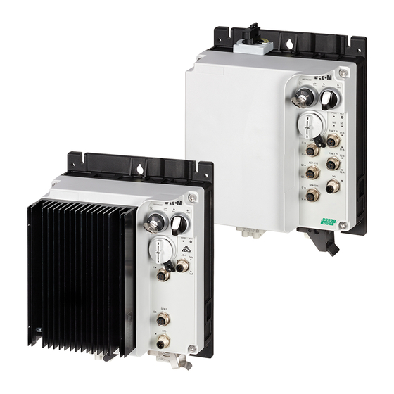
Thanks to a power bus and a data bus that are plugged into every Rapid Link 5 module, the system is quick and easy to install. The devices of the Rapid Link 5 system are available as customized solutions •... -
Page 16: System Overview
⑳ ⑰ ⑲ ③ ⑭ ⑮ 3 AC,N,PE ⑯ 50/60Hz ⑤ ⑥ ④ ⑧ ⑥ ⑦ ⑨ ⑩ ⑪ ⑬ ⑨ ⑫ Figure 1: Overview of Rapid Link 5 modules Rapid Link 5 · RAMO5 · RASP5 05/20 MN034004EN www.eaton.com... - Page 17 Screened motor cable (for RASP5) t Sensor connection via M12 plug connector u Actuator connection via M12 connector (for RAMO5) v STO connector (for RASP5) w DX-KEY-OLED operating unit view x DX-COM-STICK3-KIT Bluetooth stick Rapid Link 5 · RAMO5 · RASP5 05/20 MN034004EN www.eaton.com...
-
Page 18: Checking The Delivery
Instruction leaflet IL034084ZU or IL034092ZU. • Speed controller (speed control unit): • A RASP5 device, • Instruction leaflet IL034085ZU or IL034093ZU. Figure 2: Scope of delivery (RAMO5 or RASP5 device plus instruction leaflet) Rapid Link 5 · RAMO5 · RASP5 05/20 MN034004EN www.eaton.com... -
Page 19: Rating Data On The Nameplate
Regolat. velocità Rapid Link fino a 2,4 A Listed2ADO Ind. Conv. Eq. E172143 780000000000 Article No: 654321 Style No: RASP52402A315120100S1 35 w 19 11111111111 Made in the UK Figure 4: Name plate for RASP5 Rapid Link 5 · RAMO5 · RASP5 05/20 MN034004EN www.eaton.com... - Page 20 Maximum permissible ambient air temperature (40 °C) The speed controller is a piece of electrical equipment. Read the manual (in this case MN034004EN) before making any electrical connections and commissioning. Rapid Link 5 · RAMO5 · RASP5 05/20 MN034004EN www.eaton.com...
-
Page 21: Ramo5 Type Key
2 = two sensor inputs Direction of rotation D = DOL starter W = Reversing starter Device version 5 = RAMO5… Series RAMO Figure 5: Key to RAMO5 motor starter type references Rapid Link 5 · RAMO5 · RASP5 05/20 MN034004EN www.eaton.com... -
Page 22: Rasp5 Type Key
4 = 4.3 A rated operational current 5 = 5.6 A 8 = 8.5 A rated operational current Device version 5 = RASP5… Series RASP Figure 6: Type code of the RASP5 speed controllers Rapid Link 5 · RAMO5 · RASP5 05/20 MN034004EN www.eaton.com... -
Page 23: Technical Data
15.8 - 150 constant acceleration 2 g 15.8 - 150 constant acceleration 2 g Mechanical shock resistance (IEC/EN 1000 shocks per shaft, 1000 shocks per shaft, 60068-2-27) Semisinusoidal 15 g/11 ms Semisinusoidal 15 g/11 ms Rapid Link 5 · RAMO5 · RASP5 05/20 MN034004EN www.eaton.com... - Page 24 Allocated motor output (with motor protection) with 400 V, 0.09 - 3 0.18 - 4 50 Hz at 440 V - 460 V, 60 Hz 0.125 - 3 0.25 - 5 Rapid Link 5 · RAMO5 · RASP5 05/20 MN034004EN www.eaton.com...
- Page 25 ID-code 4 (hex) 4 (hex) 1) Assigned motor power for standard, internally and externally ventilated, three-phase asynchronous motors with 1500 rpm (at 50 Hz) and 1800 rpm (at 60 Hz) Rapid Link 5 · RAMO5 · RASP5 05/20 MN034004EN www.eaton.com...
-
Page 26: Compliance With Ul Standards
été interrompu. Pour réduire le risque d’incendie ou de choc électrique, les pièces porteuses de courant et autres composants du contrôleur devraient être examinées et remplacées s’ils sont endommagés.” Rapid Link 5 · RAMO5 · RASP5 05/20 MN034004EN www.eaton.com... - Page 27 Over-current function was evaluated. Maximum current limit is 150 percent of FLC. The adjustable range is 0 to 150 percent of FLC. Drive is provided with solid state short circuit protection circuit which is the same throughout the series. Current Rapid Link 5 · RAMO5 · RASP5 05/20 MN034004EN www.eaton.com...
- Page 28 10 000 rms symmetrical amperes, 480 volts maximum, rated 32A.” “Suitable for use on a circuit capable of delivering not more than 65 000 rms symmetrical amperes, 480 volts maximum. When protected by Type E combination motor controller model PKZM4-32 manufactured by Eaton rated 480Y/277Vac 20HP.”...
-
Page 29: Ramo5
65000 A rms symmetrical amperes, 480 V, 32 A maximum. Only for use with flexible cable connected drives is at the discretion of the AHJ. Installation may be limited to NFPA 79 applications. Rapid Link 5 · RAMO5 · RASP5 05/20 MN034004EN www.eaton.com... -
Page 30: Rasp5
30 A 32 A 32 A Interrupting Rating 10 kA 65 kA 10 kA 10 kA → Devices with an integrated repair switch are approved for use as motor disconnects (lockout/tagout). Rapid Link 5 · RAMO5 · RASP5 05/20 MN034004EN www.eaton.com... - Page 31 WARNING Operation of this equipment requires the detailed installation and operation instructions provided in the installation/operation manual intended for use with this product. Rapid Link 5 · RAMO5 · RASP5 05/20 MN034004EN www.eaton.com...
-
Page 32: Selection Criteria
• Load Torque, • Starting torque, • Ambient temperature. ATTENTION Do not disconnect or connect power connectors (mains, motor) while RAMO5 and RASP5 are operational. Rapid Link 5 · RAMO5 · RASP5 05/20 MN034004EN www.eaton.com... -
Page 33: Special Features Of Motor Selection For Rasp5
= 2.1 Ω, L* = 20 mH and U = 195 V / 1000 rpm e.g. 315 V, R → For information on and examples for permanent magnet and brushless DC motors, please refer to application note AP040051EN. Rapid Link 5 · RAMO5 · RASP5 05/20 MN034004EN www.eaton.com... -
Page 34: Proper Use
→ Rapid Link 5 is intended only for switching, protecting, and cont- rolling three-phase motors in machines and plants. Any other use is not proper use. The vendor does not accept liability for damage resulting from use other than the stated proper use. -
Page 35: Machinery Directive And Ce Mark
The technical data and connection conditions must be observed. For details, see the rating plate of the RAMO5 or RASP5 and the documenta- tion. Any other usage constitutes improper use. Rapid Link 5 · RAMO5 · RASP5 05/20 MN034004EN www.eaton.com... -
Page 36: Maintenance And Inspection
Activate and deactivate STO at least once every three months. RAMO5 or RASP5 units have not been designed to allow individual assem- blies of a device to be replaced or repaired. Rapid Link 5 · RAMO5 · RASP5 05/20 MN034004EN www.eaton.com... -
Page 37: Storage
Information concerning the warranty can be found in the terms and condi- tions of Eaton Industries GmbH. 24-hour hotline: +49 (0) 1805 223 822 Email: AfterSalesEGBonn@Eaton.com Rapid Link 5 · RAMO5 · RASP5 05/20 MN034004EN www.eaton.com... - Page 38 1 Rapid Link 5 system 1.10 Service and warranty Rapid Link 5 · RAMO5 · RASP5 05/20 MN034004EN www.eaton.com...
-
Page 39: Engineering
2.1 Rapid Link 5 modules 2 Engineering 2.1 Rapid Link 5 modules The Rapid Link 5 devices RAMO5 and RASP5 are installed in the direct vicinity of the motors. Their versions and mounting depend on the required specifications and the local conditions. -
Page 40: Versions
2 Engineering 2.1 Rapid Link 5 modules 2.1.1 Versions Examples of externally visible differences between the Rapid Link 5 modules: RAMO5-D…-0S1 • DOL starter • without repair switch RAMO5-D…-RS1 • DOL starter • with repair switch RAMO5-W…-RS1 • Reversing starter •... -
Page 41: Connections
(400/480 V AC) (400/480 V AC) Figure 9: Connections on the RAMO5 Designation Function RAMO5-xxxR Repair switches RAMO5-W… Switch for selecting the direction of rotation RAMO5-xx1… Actuator output RAMO5-xxxxA AS-Interface Rapid Link 5 · RAMO5 · RASP5 05/20 MN034004EN www.eaton.com... - Page 42 RASP 5-xxx4 (400/480 V AC) Figure 10: Connections on the RASP5 Designation Function RASP5-…-xxxR… Repair switches RASP5-xxxxA Connection to AS-Interface RASP5-xxxxx1x = no STO function RASP5-xxxxxx0xx Connection for device fan Rapid Link 5 · RAMO5 · RASP5 05/20 MN034004EN www.eaton.com...
-
Page 43: Connections In The Power Section
Connections in RAMO5 power section ④ ① ③ ② Figure 12: Connections in RASP5 power section ① 5-pin power connector HAN Q5/0 (3 AC 400 V/480 V, N, PE) ② Motor feeder socket (DESINA) Rapid Link 5 · RAMO5 · RASP5 05/20 MN034004EN www.eaton.com... - Page 44 Do not touch the heat sink → For detailed information about the connectors, see chapters → Section 3.5, Power plug, page 97 and → Section 3.6, Motor feeder, page 105 Rapid Link 5 · RAMO5 · RASP5 05/20 MN034004EN www.eaton.com...
-
Page 45: Repair Switches
2.3 Repair switches 2.3 Repair switches The device versions RAMO5-…-…RS1 and RASP5-…-…R…S1 are equipped with arepair switch that disconnects the Rapid Link 5 modules from the mains voltage in all three phases ① . Figure 13: Repair switch in position 0 = OFF →... - Page 46 After completion of maintenance or repair work, the switch can be released again and returned to position I (= ON). The motor can then be restarted with a start signal in manual or automatic mode. Rapid Link 5 · RAMO5 · RASP5 05/20 MN034004EN www.eaton.com...
-
Page 47: Electrical Power Network
(340 V - 0 % - 440 V + 0 %) (342 V - 520 V) The permitted frequency range in all voltage ranges is 50/60 Hz here (45 Hz - 0 % – 66 Hz + 0 %). Rapid Link 5 · RAMO5 · RASP5 05/20 MN034004EN www.eaton.com... -
Page 48: Voltage Balance
If this condition is not fulfilled, or symmetry at the connection location is not known, the use of a main choke in the mains-side feeder unit of the power bus is recommended. Rapid Link 5 · RAMO5 · RASP5 05/20 MN034004EN www.eaton.com... -
Page 49: Safety And Protection
2.5 Safety and protection 2.5.1 Fuses and cable cross-sections The fuses allocated for power-side connections and wire cross-sections depend on the rated mains current of the Rapid Link 5 power bus. ATTENTION When selecting the cable cross-section, take into account the voltage drop under load. -
Page 50: Residual Current Devices
RASP5. Reinforced grounding (PE) must therefore be connected in accordance with the requirements of EN 50178. The cable cross-section must be at least 10 mm or consist of two separately connected ground cables. Rapid Link 5 · RAMO5 · RASP5 05/20 MN034004EN www.eaton.com... -
Page 51: Power Bus
3 ∼ 3 ∼ Figure 17: Sample configuration of a Rapid Link 5 system with RAMO5 and RASP5 units Observe the following when planning the lengths of the power bus cabling: • On a short circuit in one pole at the end of the power bus, for example in the terminal board of the last consumer, the upstream safety device must trip. - Page 52 Depending on the power bus’ length and the configuration of the power branches, the total of all RAMO5 and RASP5 supply system currents during continuous operation must not exceed 25 A (4-mm power bus). Rapid Link 5 · RAMO5 · RASP5 05/20 MN034004EN www.eaton.com...
-
Page 53: Emc-Compliant Installation For Rasp5
Use screened motor cables (short cables). → Ground all conductive components and housings in a drive system using as short a line as possible with the greatest possible cross-section (Cu braid). Rapid Link 5 · RAMO5 · RASP5 05/20 MN034004EN www.eaton.com... -
Page 54: Safe Torque Off (Sto)
Application examples can be found in the Eaton safety manual PU05907001Z. You can find the safety manual as a PDF document on the Eaton website at the following address: http://www.eaton.eu/DE/Europe/Electrical/CustomerSupport/Techni- calLiterature/SafetyManual/index.htm Rapid Link 5 · RAMO5 · RASP5 05/20 MN034004EN www.eaton.com... -
Page 55: Safe Stop And Preventing A Restart
The STO function cannot prevent an unexpected restart or an automatic restart if the STO inputs receive a signal. Accordingly, it must not be used to perform maintenance or cleaning work on the machine. Rapid Link 5 · RAMO5 · RASP5 05/20 MN034004EN www.eaton.com... -
Page 56: Tüv Certification
This safety function corresponds to uncontrolled shutdown as defined in IEC60204-1, Stop category 0. → The following information and descriptions for the STO function are translations of the original description in English (TÜV speci- fication). Rapid Link 5 · RAMO5 · RASP5 05/20 MN034004EN www.eaton.com... -
Page 57: Sto-Compatible Installation
The 24 V DC power supply for the STO inputs can be sup- plied from the RASP5 internal 24 V DC voltage or from an external 24 V DC power supply. The RASP5 must be wired as described below. Rapid Link 5 · RAMO5 · RASP5 05/20 MN034004EN www.eaton.com... - Page 58 (ESC, separate mechanical protection with two closed cable ducts or two conduits). These two separately wired single cables must be screened, and the corresponding cable screen must be earthed (PES). Rapid Link 5 · RAMO5 · RASP5 05/20 MN034004EN www.eaton.com...
- Page 59 The external control voltage should meet the following specifications: Rated control voltage 24 V DC Voltage for the logical STO high signal 18 - 30 V DC Current carrying capacity 100 mA Rapid Link 5 · RAMO5 · RASP5 05/20 MN034004EN www.eaton.com...
-
Page 60: Direct Enable
InHibit will be displayed. The STO LED stays off. WARNING This function is not suitable for continuous operation! WARNING For applications without a safety function, devices without STO function can be used. Rapid Link 5 · RAMO5 · RASP5 05/20 MN034004EN www.eaton.com... -
Page 61: Sto Function Pick-Up Time
Table 8: Error Messages Keypad display LED display STO Meaning there is no release Inhibit Green there is release StOP Internal STO fault Sto-F Rapid Link 5 · RAMO5 · RASP5 05/20 MN034004EN www.eaton.com... -
Page 62: Sto Function Checklist
The motor is running while being controlled by the RASP5and an STO input is de-energized. InHibit is displayed and the motor coasts to a stop. The STO LED is off. Rapid Link 5 · RAMO5 · RASP5 05/20 MN034004EN www.eaton.com... -
Page 63: Regular Maintenance
The enclosure fan and air filter must provide the required airflow. • Check all electrical connections: The screw terminals must be properly tightened and the power cables must not show any signs of heat damage. Rapid Link 5 · RAMO5 · RASP5 05/20 MN034004EN www.eaton.com... -
Page 64: Application Of The Sto Function And Safety Parameters
1 % per 100 m above 1000 m (up to max. 4000 m IEC/max. 2000 m UL). • Relative humidity: < 95 % (non-condensing). The RASP5 speed controller must always be free of frost and moisture. Rapid Link 5 · RAMO5 · RASP5 05/20 MN034004EN www.eaton.com... -
Page 65: Sensor Inputs
2 Engineering 2.9 Sensor inputs 2.9 Sensor inputs Figure 23: Connection sockets of sensor inputs The RAMO5 and RASP5 Rapid Link 5 modules have two M12 sockets for direct connection of sensors. PWR FLT AS-I Data SEN I1/I3 Fault –... - Page 66 Sensor cable coding sensors contact contact ∑ I ≦ 160 mA; 24 V DC Mechanical sensors A coded (IEC/EN 60947-5-2) 1 = brown 2 = white 3 = blue 4 = black Rapid Link 5 · RAMO5 · RASP5 05/20 MN034004EN www.eaton.com...
- Page 67 +24 V DC/160 mA – SEN I2 – Configuration +24 V DC (160 mA) – output Not used 0 V (reference potential) Sensor input Not used Figure 25: Pin assignment for RAMO5 Rapid Link 5 · RAMO5 · RASP5 05/20 MN034004EN www.eaton.com...
- Page 68 RESET command. In addition, the S1 bit will be set to high during a short-circuit (peripheral fault). It will be set back to low automatically once the short-circuit is eliminated. Rapid Link 5 · RAMO5 · RASP5 05/20 MN034004EN www.eaton.com...
- Page 69 Da ta SE N I1 /I3 Fa ul t SE N I2 /I4 ST O ≦ 20 m (≦ 65.6 ft) Figure 26: Connection to sensor inputs (RASP5 as an example) Rapid Link 5 · RAMO5 · RASP5 05/20 MN034004EN www.eaton.com...
-
Page 70: Actuator Output
The actuator output is short-circuit proof. In the event of an overload or short-circuit, a group fault signal will be genera- ted and the FLT LED will light up red to indicate this. Rapid Link 5 · RAMO5 · RASP5 05/20 MN034004EN www.eaton.com... -
Page 71: Device Fan Connection
– Not used Figure 27: Device fan connection The output voltage at the device fan connection is 24 V DC and is automati- cally controlled by the RASP5 speed controller. Rapid Link 5 · RAMO5 · RASP5 05/20 MN034004EN www.eaton.com... - Page 72 – especially after changes are made to the safety system and after repairs are made. Rapid Link 5 · RAMO5 · RASP5 05/20 MN034004EN www.eaton.com...
-
Page 73: Motor And Application
The rated operational current of the motor with 2 A at 400 V requires a Rapid Link module (RAMO5 or RASP5) with a rated operational current of at least 2 A. Rapid Link 5 · RAMO5 · RASP5 05/20 MN034004EN www.eaton.com... -
Page 74: Direction Reversal
Example showing how to change the phase sequence Table 9: Phase sequence (only for RAMO5-W… and RASP5…) P6-08 Phase sequence U – V – W W – V – U Rapid Link 5 · RAMO5 · RASP5 05/20 MN034004EN www.eaton.com... -
Page 75: Quick Stop
Preprocessing in RAMO5 or RASP5 enables the motor to be switched off directly. PLC and bus cycle times have no influ- ence on the switch-off time. Rapid Link 5 · RAMO5 · RASP5 05/20 MN034004EN www.eaton.com... -
Page 76: Interlocked Manual Operation
(on I1, for example) with a continuous signal. The motor can then be operated in Manual and Auto mode with an opposite direction of rotation in RAMO5-W and RASP5 units. Rapid Link 5 · RAMO5 · RASP5 05/20 MN034004EN www.eaton.com... - Page 77 The FWD or REV LED flashes when the selector switch is operated, but RAMO5 or RASP5 is switched off by interlocked manual operation (as an example of interlocked manual operation in RASP5). Rapid Link 5 · RAMO5 · RASP5 05/20 MN034004EN www.eaton.com...
-
Page 78: External Brake
In this case, the brake is supplied with AC power through a functional rectifier built into the motor. RAMO5 and RASP5 Rapid Link 5 modules feature a fast, internal electronic switch for powering and actuating the external motor brake. It is connected using pin 4 and pin 6 of the motor feeder socket. - Page 79 The frequency drops and the brake is applied when the output frequency falls below the value set in P3-03. → The drive continues the ramp to a standstill. → The output of the drive is disabled. Rapid Link 5 · RAMO5 · RASP5 05/20 MN034004EN www.eaton.com...
- Page 80 Brake Release Delay Determines the time before the mechanical brake is released. P3-05 Brake Apply Delay Determines the time between the signal to close the mechanical brake and the drive being disconnected. Rapid Link 5 · RAMO5 · RASP5 05/20 MN034004EN www.eaton.com...
-
Page 81: Regenerative Braking
The braking chopper function must be activated in parameter P4-05. The braking chopper is switched on automatically if the braking energy being fed back causes the DC-Link Voltage to increase to the switch-on voltage of the braking chopper. Rapid Link 5 · RAMO5 · RASP5 05/20 MN034004EN www.eaton.com... - Page 82 100 W Isolation voltage V 4000 V Maximum barrier layer temperature T 125 °C jmax Switch-on threshold for the braking transistor U to: 780 V DC OFF 756 V DC Rapid Link 5 · RAMO5 · RASP5 05/20 MN034004EN www.eaton.com...
-
Page 83: Thermistor And Motor Cable Monitoring
Device response (depending on device) – Motor thermistor after “Thermistor Fault” occurs. fault 0: Disabled (OFF) 1: Enabled (ON) ATTENTION The setting of parameter P2-27 may only be changed by trained specialist personnel! Rapid Link 5 · RAMO5 · RASP5 05/20 MN034004EN www.eaton.com... - Page 84 2 Engineering 2.15 Thermistor and motor cable monitoring Rapid Link 5 · RAMO5 · RASP5 05/20 MN034004EN www.eaton.com...
-
Page 85: Installation
Refer to the appropriate RAMO5 or RASP5 instruction leaflets for the required installation instructions. Instruction leaflet for RAMO5: • IL034084ZU • IL034092ZU (variant “EtherNet/IP”) Instruction leaflet for RASP5: • IL034085ZU • IL034093ZU (variant “EtherNet/IP”) Rapid Link 5 · RAMO5 · RASP5 05/20 MN034004EN www.eaton.com... -
Page 86: Mounting Position
3 Installation 3.2 Instruction leaflets 3.2.1 Mounting position RAMO5 and RASP5 Rapid Link 5 modules are preferably installed vertically. F 30° F 30° F 30° F 90° F 30° F 90° F 90° F 90° Figure 37: RAMO5 mounting position... -
Page 87: Clearances
Clearances for thermal air cooling (example: RASP5) Depending on the version, thermal clearances must be provided around the RAMO5 and RASP5 Rapid Link 5 modules. Unobstructed handling must also be ensured for versions with a repair and maintenance switch (RAMO5-…-...RS1 and RASP5-…-...R…S1) and in the area of the plug-in power connections ②. -
Page 88: Attachment
3 Installation 3.2 Instruction leaflets 3.2.3 Attachment Rapid Link 5 devices RAMO5 and RASP5 are mounted with screws. → Mount RAMO5 and RASP5 units on a non-flammable mounting base only (e.g., on a metal plate). → Details of RAMO5 and RASP5 unit weights and dimensions can be found in the corresponding technical data. - Page 89 Tighten the screws to a torque of 1.3 Nm. Vertical arrangement, center fixing 110 mm (4.33”) 110 mm (4.33”) Figure 41: Fixing dimensions (center) Two M6 screws, tightening torque 1.3 Nm. Rapid Link 5 · RAMO5 · RASP5 05/20 MN034004EN www.eaton.com...
- Page 90 Tighten the screws to a torque of 1.3 Nm. Horizontal arrangement, center fixing (base rotated by 90°) 245 mm (9.65") Figure 43: Fixing dimensions (center) Two M6 screws, tightening torque 1.3 Nm. Rapid Link 5 · RAMO5 · RASP5 05/20 MN034004EN www.eaton.com...
-
Page 91: Position Of The Power Connections
90° to the left or right. To do this, remove the four screws in the enclosure cover. TORX 30 IP Figure 44: Dismantling the enclosure cover ▶ Fix the enclosure cover at the side and lift off carefully. Rapid Link 5 · RAMO5 · RASP5 05/20 MN034004EN www.eaton.com... - Page 92 For example, tighten all four screws to about 2 Nm and then to 3 Nm, always working in a crosswise pattern. ▶ Use a suitable tool (TORX 30 IP) to tighten the screws with a torque of 3 Nm. Rapid Link 5 · RAMO5 · RASP5 05/20 MN034004EN www.eaton.com...
- Page 93 TORX 30 IP 3 Nm (26.55 lb-in) Figure 47: Attaching the M32 screw-on cover ▶ Tighten the M32 screw-on cover using the required tool with a torque of 2 Nm. Rapid Link 5 · RAMO5 · RASP5 05/20 MN034004EN www.eaton.com...
-
Page 94: Electrical Installation
On RASP5 units, only disconnect the motor feeder cable and only perform work on the motor terminal box after the dischar- ging time has elapsed. 3.4 Power bus The Rapid Link 5 system can have one of two types of power bus: • Flexible (RA-C1-7…) busbar, •... -
Page 95: Flexible Busbar (Ra-C1-7
Figure 48: Keying on RA-C1-7… flexible busbar a Hinge → L+ and M are not used on the RAMO5 and RASP5 Rapid Link 5 modules. → RAMO5 and RASP5 must always be connected to the power bus with five conductors: L1, L2, L3, N, PE. - Page 96 When using a standard cable stripper, do not cut into the rubber sheath by more than 0.7 mm in order to avoid damaging the insulation of the conductor. Figure 51: RA-C1-AZ-4 Tool for stripping the cable sheath Rapid Link 5 · RAMO5 · RASP5 05/20 MN034004EN www.eaton.com...
- Page 97 Wire number (7 x 4 mm +24 V yellow/green 1) Not used on RAMO5 and RASP5. N L1 PE L2 L3 Figure 53: Pin assignment of the RA-C1-PLF1 Flexible busbar junction Rapid Link 5 · RAMO5 · RASP5 05/20 MN034004EN www.eaton.com...
-
Page 98: Round Cable
13 to 16 mm are always included as standard. Only these matched seal inserts installed correctly guarantee protection class IP65. → The round cable must be laid without tension. Install only one conductor per terminal. Rapid Link 5 · RAMO5 · RASP5 05/20 MN034004EN www.eaton.com... - Page 99 Slot the attached locking clip for the outgoer plug onto the two studs of the bushing housing. → The open end of the last round cable junction (at the end of the power bus) must be sealed off using an RA-C2-SBL end piece. Rapid Link 5 · RAMO5 · RASP5 05/20 MN034004EN www.eaton.com...
- Page 100 RA-C4-PB65 round cable junction (power box) → The power box's IP65 enclosure is supplied without gaskets (RA-C4-D… or RA-CU-PB65 required). Seals RA-C4-D… Figure 57: Enclosure Figure 58: Dummy plugs Grommets (RA-C4-D0) Rapid Link 5 · RAMO5 · RASP5 05/20 MN034004EN www.eaton.com...
-
Page 101: Power Plug
Two types of power plugs are available. RA-C3… (for RAMO5…512…) Figure 59: Energy connector RA-C3… Table 17: Pin assignment of the RA-C3… power plug of type HANQ5/0 Function Power plug – Rapid Link 5 · RAMO5 · RASP5 05/20 MN034004EN www.eaton.com... - Page 102 3 Installation 3.5 Power plug RA-C3/C1-1, 5HF RA-C3/C2-1, 5HF RA-C4-PPB/C3-1M5 → RA-C1-PLF1 → RA-C2-S1-4 → RA-C4-PB65 Rapid Link 5 · RAMO5 · RASP5 05/20 MN034004EN www.eaton.com...
- Page 103 3.5 Power plug RA-Q4… (for RAMO5…412…) Figure 60: Energy connector RA-Q4… Table 18: Pin assignment of the RA-Q4… power plug of type HANQ4/2-F. Function Power plug – – – Rapid Link 5 · RAMO5 · RASP5 05/20 MN034004EN www.eaton.com...
- Page 104 → RA-C2-S1-4 → RA-C4-PB65 After installing the power bus outgoers (RA-C1-PLF1, RA-C2-S1-4, RARA-C4- PB65), you can connect the Rapid Link 5 module RAMO5 to the power plug using the assigned power adapter cables. ATTENTION Compatibility with cables from other manufacturers cannot be guaranteed! Rapid Link 5 ·...
-
Page 105: Rasp5
Two types of power plugs are available. RA-C3… (for RASP5…512…) DANGER 5 MIN Figure 61: Energy connector RA-C3… Table 19: Pin assignment of the RA-C3… power plug of type HANQ5/0 Function Power plug – Rapid Link 5 · RAMO5 · RASP5 05/20 MN034004EN www.eaton.com... - Page 106 3 Installation 3.5 Power plug RA-C3/C1-1, 5HF RA-C3/C2-1, 5HF RA-C4-PPB/C3-1M5 → RA-C1-PLF1 → RA-C2-S1-4 → RA-C4-PB65 Rapid Link 5 · RAMO5 · RASP5 05/20 MN034004EN www.eaton.com...
- Page 107 3 Installation 3.5 Power plug RA-Q4… (for RASP5…412…) Figure 62: Energy connector RA-Q4… Table 20: Pin assignment of the RA-Q4… power plug of type HANQ4/2-F. Function Power plug – – Rapid Link 5 · RAMO5 · RASP5 05/20 MN034004EN www.eaton.com...
- Page 108 → RA-C2-S1-4 → RA-C4-PB65 After installing the power bus outgoers (RA-C1-PLF1, RA-C2-S1-4, RARA-C4- PB65), you can connect the Rapid Link 5 module RASP5 to the power plug using the assigned power adapter cables. ATTENTION Compatibility with cables on plug connectors from other manu- facturers cannot be guaranteed! Rapid Link 5 ·...
-
Page 109: Motor Feeder
Temperature sensor (T1, T2) • Motor brake (B1, B2) Function Pin arrangement Motor feeder socket Plug connector U1 motor Coding W 1 Motor B2 brake T1 thermistor B1 brake V1 motor T2 thermistor Rapid Link 5 · RAMO5 · RASP5 05/20 MN034004EN www.eaton.com... -
Page 110: Motor Feeder Connection Examples
Metal connectors for RASP5 Figure 63: Motor cable for connecting the motor starter to the motor ATTENTION Compatibility with cables on plug connectors from other manu- facturers cannot be guaranteed! Rapid Link 5 · RAMO5 · RASP5 05/20 MN034004EN www.eaton.com... - Page 111 The cable ends (pin 5 and pin 8) on motors with thermistors or thermostats (Thermo-Click) must be connected in the terminal box of the motor (T1–T2). Rapid Link 5 · RAMO5 · RASP5 05/20 MN034004EN www.eaton.com...
- Page 112 230 V RASP5-xxx4… 400 V The connection is made using pin 4 and pin 6 in the motor plug (→ Page 105) 3 ∼ Figure 66: General connection with brake Rapid Link 5 · RAMO5 · RASP5 05/20 MN034004EN www.eaton.com...
-
Page 113: Rasp5 Motor Feeder
The RASP-CM2-2M0 motor cable (or RASP-CM2-5M0, RASP-CM2-10M) is grounded on the device side. ATTENTION The motor’s metal enclosure must always be earthed - irrespec- tive of the type and version of motor cable used! Rapid Link 5 · RAMO5 · RASP5 05/20 MN034004EN www.eaton.com... -
Page 114: Screened Motor Cable For Rasp5
T1/T2 are covered and connected with each other. → Cover the screen ends with a rubber grommet or with insulating tape or textile tape, so that the screen braid does not fray. Rapid Link 5 · RAMO5 · RASP5 05/20 MN034004EN www.eaton.com... - Page 115 The screen clamp shown in the illustration is an example of a large-area ground connection (PES). W PE Figure 70: Connect the screen mesh (PES) to the motor terminal box Rapid Link 5 · RAMO5 · RASP5 05/20 MN034004EN www.eaton.com...
- Page 116 (inadvertent loosening of the locking clips) we recommend securing the plug-in connections with a cable binder at the locking clip. Figure 71: Secure the motor feeder plug using cable ties Rapid Link 5 · RAMO5 · RASP5 05/20 MN034004EN www.eaton.com...
-
Page 117: Isolation Test
3 Installation 3.7 Isolation test 3.7 Isolation test The RAMO5 and RASP5 Rapid Link 5 modules are delivered pre-tested and require no additional testing. DANGER Do not perform insulation resistance tests with an insulation tester at the control terminals (SI1, SI2, SI3, SI4, AS-Interface, etc.) and power terminals (power plug and motor feeder plug). - Page 118 3 Installation 3.7 Isolation test Rapid Link 5 · RAMO5 · RASP5 05/20 MN034004EN www.eaton.com...
-
Page 119: Operation
Each single phase of the supply voltage (power bus L1, L2, L3) is protected with a fuse. The RAMO5 and RASP5 Rapid Link 5 modules and the motor are adapted to the mains voltage. → Section 1.3, Rating data on the nameplate, page 15, connection type (star, delta) of the motor has been tested. -
Page 120: Operational Warnings
Do not remove the motor plug or power plug when the system is live. DANGER The output to the brake carries a dangerous voltage whenever the supply voltage is switched on - even if in the OFF state! Rapid Link 5 · RAMO5 · RASP5 05/20 MN034004EN www.eaton.com... -
Page 121: Specific Hazard Warnings For Rasp5
High temperatures may occur on the heat sink of the RASP5 during operation. ACHTUNG Hohe Temperatur Kühlkörper nicht berühren Heat sink WARNING HOT SURFACE Do not touch! Do not touch the heat sink Rapid Link 5 · RAMO5 · RASP5 05/20 MN034004EN www.eaton.com... - Page 122 4.2 Operational warnings ATTENTION Make sure that no danger will be caused by starting the motor. Disconnect the driven machine if there is a danger in an incor- rect operating state. Rapid Link 5 · RAMO5 · RASP5 05/20 MN034004EN www.eaton.com...
-
Page 123: Manual Control
4.3 Manual control 4.3 Manual control RAMO5 and RASP5 Rapid Link 5 modules come with a manual controller (local controller) as standard. This controller is made up of a key switch and, in the case of RAMO5-W and RASP5, of a direction selector switch. - Page 124 The selected and enabled rotating field direction is indicated by the green FWD and REV LEDs. The selector switch for the rotating field direction has three positions. When the switch is in the OFF position, the Rapid Link 5 modules are locked in Manual mode. →...
-
Page 125: Ramo5 Motor Starter
Actuator output Q1 (M12 connector) with LED display - only in the version RAMO5-xx1… k Sensor input I2 (M12 socket) with LED l Motor feeder plug m Power plug, (supply voltage 3 AC 400 V, N, PE) Rapid Link 5 · RAMO5 · RASP5 05/20 MN034004EN www.eaton.com... -
Page 126: Features
DC air solenoid valve. A controlled supply voltage of 180 V AC, 230 V AC or 400 V AC is output for the brake rectifier (→ Figure 64, page 107). DANGER Open only in voltage-free state! Rapid Link 5 · RAMO5 · RASP5 05/20 MN034004EN www.eaton.com... -
Page 127: Connections
(→ Section 3.5, Power plug, page 97) b Data bus for controlling RAMO5 in automatic mode c Motor connection: Motor feeder socket according DESINA specifications d Sensor and fan actuators Rapid Link 5 · RAMO5 · RASP5 05/20 MN034004EN www.eaton.com... -
Page 128: Specific Technical Data
Switch off the motor (quick stop) Motor 20-35, brake 20-35 Switch on Q1 2 - 20 Switch off Q1 2 - 20 Minimum pulse duration I1/I2 1) without bus runtime, depending on PLC Rapid Link 5 · RAMO5 · RASP5 05/20 MN034004EN www.eaton.com... -
Page 129: Block Diagrams
5 RAMO5 motor starter 5.5 Block diagrams 5.5 Block diagrams RAMO5-DxxxA… Figure 77: Block diagram of RAMO5-D… a RAMO5-…-xxxRxx b RAMO5-xxx2… (230/277 V), RAMO5-xxx4… (400/480 V) c RAMO5-xx1… Rapid Link 5 · RAMO5 · RASP5 05/20 MN034004EN www.eaton.com... - Page 130 5 RAMO5 motor starter 5.5 Block diagrams RAMO5-WxxxA… Figure 78: Block diagram RAMO5-W… Rapid Link 5 · RAMO5 · RASP5 05/20 MN034004EN www.eaton.com...
-
Page 131: Led Indicators
Red flashing Fault No data exchange, communication error Red flashing Peripheral fault, Sensor input SEN I1 • not connected • not triggered (no input signal) Green SEN I1 triggered (input signal) Rapid Link 5 · RAMO5 · RASP5 05/20 MN034004EN www.eaton.com... - Page 132 The detected fault (the fault signal's cause) has been fixed. The fault signal can now be acknowledged in the OFF/RESET position using the key switch. → The FLT LED goes out. Rapid Link 5 · RAMO5 · RASP5 05/20 MN034004EN www.eaton.com...
-
Page 133: Configure Specialist Settings
Figure 79: RJ 45 interface The parameterization can be via : • drivesConnect software • Keypad • drivesConnect mobile app ATTENTION The RJ45 interface is not designed for Ethernet communication. Rapid Link 5 · RAMO5 · RASP5 05/20 MN034004EN www.eaton.com... -
Page 134: Set The Rated Motor Current (P1-08)
ϕ 0.79 1410 mi n 50 Hz Figure 80: Set rated motor current Table 23: Parameter P1-08 Parameter Description Unit Value range P1-08 Nominal motor current 0.3 - 6.6 Rapid Link 5 · RAMO5 · RASP5 05/20 MN034004EN www.eaton.com... -
Page 135: Sensor Inputs
A change only becomes active after POWER ON/OFF. P3-07 SEN I2 logic 0: N/O closing contact – 1: N/C opening contact Note: A change only becomes active after POWER ON/OFF. Rapid Link 5 · RAMO5 · RASP5 05/20 MN034004EN www.eaton.com... -
Page 136: Quick Stop And Interlocked Manual Mode
REV: from FWD and loss of SEN I2 for edge control or level control REV: Key switch reset and SEN I2 no longer active for edge control or level control Rapid Link 5 · RAMO5 · RASP5 05/20 MN034004EN www.eaton.com... -
Page 137: Phase Change
0: U – V – W (clockwise rotating field) 1: U – W – V (counterclockwise rota- ting field) Rapid Link 5 · RAMO5 · RASP5 05/20 MN034004EN www.eaton.com... -
Page 138: Monitoring The Low Current Limit
P5-10 Function Description Quick stop ON Response to sensors Quick stop OFF No response to sensors None DQ3 signals will not be transmitted None DQ3 signals will not be transmitted Rapid Link 5 · RAMO5 · RASP5 05/20 MN034004EN www.eaton.com... -
Page 139: Rasp5 Speed Controller
STO input, with LED indicator m Motor output plug n Power plug, (supply voltage 3 AC 400 V, N, PE) o Device fan, mounted at the factory on RASP5-8… (4 kW) Rapid Link 5 · RAMO5 · RASP5 05/20 MN034004EN www.eaton.com... -
Page 140: Features
277 V AC or 400 V / 480 V AC is output for the brake rectifier. In addition, versions of RASP5 with built-in brake resistors also allow dyna- mic braking. DANGER Open only in voltage-free state! Rapid Link 5 · RAMO5 · RASP5 05/20 MN034004EN www.eaton.com... -
Page 141: Connections
Power supply (3 AC 400 V, N, PE) through a power adapter cable (→ Section 3.5, Power plug, page 97) b Data bus for controlling RASP5 in automatic mode c Motor connection according DESINA specification d Sensor and fan actuators Rapid Link 5 · RAMO5 · RASP5 05/20 MN034004EN www.eaton.com... -
Page 142: Specific Technical Data
(380 - 480 V ±0 %, 45 - 66 Hz ±0 %) Input current Braking Braking value ≦ 30 ≦ 30 ≦ 30 ≦ 30 Switch-on threshold for the V DC braking transistor Rapid Link 5 · RAMO5 · RASP5 05/20 MN034004EN www.eaton.com... - Page 143 < 10 Minimum pulse duration I3/I4 longest permissible length of motor cable (EMC, 2nd environment, C3) Weight 3.4/3.7 3.4/3.7 3.4/3.7 3.4/3.8 (Without/with repair switch) 1) without bus runtime, depending on PLC. Rapid Link 5 · RAMO5 · RASP5 05/20 MN034004EN www.eaton.com...
-
Page 144: Overload Capacity
60 s or 200 % I for 2 s), 100 % of the rated current I can be continuously retrieved. 150 % I 60 s 600 s Figure 84: Overload cycle in operation Rapid Link 5 · RAMO5 · RASP5 05/20 MN034004EN www.eaton.com... -
Page 145: Derating Curves
= 8 - 32 kHz with RASP5-2…, RASP5-4…, RASP5-5… RASP5 - 8... 4 kHz 8 kHz 12 kHz 16 kHz 24 kHz 32 kHz ϑ [°C] Figure 86: = 4 - 32 kHz with RASP5-8… Rapid Link 5 · RAMO5 · RASP5 05/20 MN034004EN www.eaton.com... -
Page 146: Block Diagram
6 RASP5 speed controller 6.5 Block diagram 6.5 Block diagram RASP5-xxxxA… Rapid Link 5 · RAMO5 · RASP5 05/20 MN034004EN www.eaton.com... - Page 147 6.5 Block diagram Figure 87: RASP5 block diagram a RASP5-…-xxxR… b RASP5-xx1… (180 V DC) RASP5-xx2… (230/277 V AC) RASP5-xx4… (400/480 V AC) c RASP5-…-xxxxxx1xx (FAN) d RASP5-…-xxx1... e RASP5-…-xxxxx1xxx (STO) Rapid Link 5 · RAMO5 · RASP5 05/20 MN034004EN www.eaton.com...
-
Page 148: Led Indicators
Red flashing Fault No data exchange, communication error Red flashing Peripheral fault, Sensor input I1 • not connected • Not triggered (no input signal) Green SEN I1 triggered (input signal) Rapid Link 5 · RAMO5 · RASP5 05/20 MN034004EN www.eaton.com... - Page 149 The detected fault (the fault signal's cause) has been fixed. The fault signal can now be acknowledged in the OFF/RESET position using the key switch. Safe Torque Off No enable for STO hardware Green Enable present for STO hardware Rapid Link 5 · RAMO5 · RASP5 05/20 MN034004EN www.eaton.com...
-
Page 150: Configuration Of Specific Settings
Figure 88: RJ 45 interface The parameterization can be done via : • drivesConnect software • Keypad • drivesConnect mobile app ATTENTION The RJ45 interface is not designed for Ethernet communication. Rapid Link 5 · RAMO5 · RASP5 05/20 MN034004EN www.eaton.com... -
Page 151: Set The Rated Motor Current (P1-08)
ϕ 0.79 1410 mi n 50 Hz Figure 89: Set rated motor current Table 26: Parameter P1-08 Parameter Description Unit Value range P1-08 Nominal motor current 0.3 - 6.6 Rapid Link 5 · RAMO5 · RASP5 05/20 MN034004EN www.eaton.com... -
Page 152: Sensor Inputs
0: N/O closing contact – 1: N/C opening contact Note: A change only becomes active after POWER ON/OFF. → Sensors SEN I3 and SEN I4 require a Y connector of the type RA-XM12-Y. Rapid Link 5 · RAMO5 · RASP5 05/20 MN034004EN www.eaton.com... -
Page 153: Quick Stop And Interlocked Manual Operation
RASP5… switches to creep speed FF1. When SEN I1/SEN I2 is reached, the drive switches off. Application example: Turntable Note: SEN I3 and SEN I4 require a RA-XM12-Y Y connector. Rapid Link 5 · RAMO5 · RASP5 05/20 MN034004EN www.eaton.com... - Page 154 FWD operation with fixed REV operation with fixed edge or signal control control frequency 1 (f-Fix1) with edge frequency 1 (f-Fix1) with edge control or signal control control or signal control Rapid Link 5 · RAMO5 · RASP5 05/20 MN034004EN www.eaton.com...
- Page 155 Signal to drive ① Signal from key and selector switch Figure 92: Interlocked manual mode with creep speed (Example of sensor input I1 and clockwise rotation) a 13.5 ms ± 5 ms Rapid Link 5 · RAMO5 · RASP5 05/20 MN034004EN www.eaton.com...
-
Page 156: Phase Change
Monitoring is carried out using parameter P2-27. Parameter P2-27 is set to the value 1 in the factory setting. In position 0, the fault message of the thermistor and motor cable monitoring is deactivated. Rapid Link 5 · RAMO5 · RASP5 05/20 MN034004EN www.eaton.com... -
Page 157: Stop Behavior
+24 V DC 100 mA External Power Supply Figure 93: Example of a 24 V DC power connection → The second deceleration time can be set using the parameter P2-13. Rapid Link 5 · RAMO5 · RASP5 05/20 MN034004EN www.eaton.com... - Page 158 6 RASP5 speed controller 6.7 Configuration of specific settings Rapid Link 5 · RAMO5 · RASP5 05/20 MN034004EN www.eaton.com...
-
Page 159: Parameterization
7 Parameterization The following section contains special information on configuring the Rapid Link 5 module in order to adapt it to your requirements. A change of the parameter values requires a connection with the RJ45 socket. The socket is located under the screw plug on the front. - Page 160 Connect the module to the tablet or smartphone using the DX-COM- STICK3-KIT Bluetooth stick. Figure 96: Connection using the DX-COM-STICK3-KIT Bluetooth stick Top: for the RAMO5, bottom: for the RASP5 Rapid Link 5 · RAMO5 · RASP5 05/20 MN034004EN www.eaton.com...
- Page 161 Changing the parameter range to P1-14 = 201 requires additio- nal configuration and meticulous parameter settings. The operation and function of the Rapid Link 5 may considerably deviate from the standard settings of the Rapid Link 5 system and lead to different operating statuses.
-
Page 162: Configuration Using The Drivesconnect Software
Function block editor (not available with Rapid Link 5) • Scope/data logger Parameter Editor The Parameter Editor contains a list of the parameters of the respective Rapid Link 5 module. These parameters can be manually changed and accessed. drivesConnect Parameter-Editor Antriebssteuerung / Monitor... - Page 163 User interface for the Parameter Editor when using RAMO Figure 100: User interface for the Parameter Editor when using RASP → More information on the drivesConnect software can be found in the MN040003EN manual. Rapid Link 5 · RAMO5 · RASP5 05/20 MN034004EN www.eaton.com...
-
Page 164: Parameterization Using Oled Operating Unit
7.2 Parameterization using OLED operating unit 7.2 Parameterization using OLED operating unit The parameters of the Rapid Link 5 system can be configured and its opera- tion monitored using the DX-KEY-OLED operating unit. The figure below shows the DX-KEY-OLED operating unit. -
Page 165: Dx-Key-Oled Operating Unit Elements
• Saves parameter changes START • Parameter selection STOP • Reset – Reset after an error message • Increment numeric value or parameter number. DOWN • Decrement numeric value or parameter number. Rapid Link 5 · RAMO5 · RASP5 05/20 MN034004EN www.eaton.com... -
Page 166: Set Parameters
STOP buttons to jump to the first parameter in the next parameter group. ▼ Press the and STOP buttons to jump to the first parameter in the previous parameter group. Rapid Link 5 · RAMO5 · RASP5 05/20 MN034004EN www.eaton.com... -
Page 167: Reset Parameters (Reset)
P1-14 that does not match the password (P2-32). Press the OK button to confirm. -> Only the basic parameters, i.e. the parameters in the first parameter group (P1-01 to P1-14), will now be accessible. Rapid Link 5 · RAMO5 · RASP5 05/20 MN034004EN www.eaton.com... -
Page 168: Configure Parameters Using An App
For more information on configuring parameters using the app, please visit the Eaton Download Center. www.eaton.eu → Customer Support → Download Center - Documentation Enter the search string AP040189 in the Quick search field and click on Search. Rapid Link 5 · RAMO5 · RASP5 05/20 MN034004EN www.eaton.com... -
Page 169: Parameter List
8 Parameter list 8.1 Parameter Groups 8 Parameter list 8.1 Parameter Groups The functions of the RAMO5 and RASP5 Rapid Link 5 modules are configu- red using parameters that are divided into 8 groups (P0 to P7): Table 34: Parameter Groups... -
Page 170: Menu Structure
Time elapsed, in which the drive has operated with a high temperature at the hh:mm:ss PCBs (ambient temperature) Displays the time in hours and minutes above 80 °C. The value is used for various internal protective functions. Rapid Link 5 · RAMO5 · RASP5 05/20 MN034004EN www.eaton.com... - Page 171 AmbientTemp Log Internal Ambient Temperature Log °C Displays the most recent 8 samples of the internal ambient temperature prior to a drive trip condition occurring. The sample interval is 30 s. Rapid Link 5 · RAMO5 · RASP5 05/20 MN034004EN www.eaton.com...
- Page 172 This ID can be set by the user when developing the program. P0-59 Value@Pointer Pointer on an internal parameter – Displays the value selected with P5-09. P0-60 Reserved – – P0-61 Reserved – – Rapid Link 5 · RAMO5 · RASP5 05/20 MN034004EN www.eaton.com...
-
Page 173: Parameter Group 1 (Basic)
The value to be put in is determined by the level to be accessed. Level 2 (access to parameter groups 0 to 8): P1-14 = P2-32 (factory setting: 101) Rapid Link 5 · RAMO5 · RASP5 05/20 MN034004EN www.eaton.com... -
Page 174: Parameter Group 2 (Extended Functions)
0: OFF. All parameters can be accessed and changed 1: ON. Parameter values can be displayed, but cannot be changed. If a remote keypad is connected, parameters cannot be accessed by the remote keypad if they are locked. Rapid Link 5 · RAMO5 · RASP5 05/20 MN034004EN www.eaton.com... - Page 175 List of defined parameters – 0: No function – automatically set to 0. 1: If control voltage is present, the Parameters will be saved. After that, the parameter is automatically set to 0. Rapid Link 5 · RAMO5 · RASP5 05/20 MN034004EN www.eaton.com...
-
Page 176: Parameter Group 3 (Mechanical Brake And Digital Inputs)
1: normally closed Note: Change only after POWER ON / OFF active P3-09 SEN I4 Logic 0: normally open – 1: normally closed Note: Change only after POWER ON / OFF active Rapid Link 5 · RAMO5 · RASP5 05/20 MN034004EN www.eaton.com... -
Page 177: Parameter Group 5 (Communication)
Configuration of the 4th process data word PDI-4 from the network – master to the drive during cyclic communication. 0: reserved P5-10 Disable QuickStop 0: Quick stop via sensors deactivated – 1: Quick stop via sensors activated; AS-i signal active Rapid Link 5 · RAMO5 · RASP5 05/20 MN034004EN www.eaton.com... -
Page 178: Parameter Group 6 (Extended Motor Control)
This prevents two phases of the motor cable having to be changed in case the motor runs in the wrong direction. 0: U–V–W (clockwise rotating field) 1: U–W–V (counterclockwise rotating field) Note: Only for RASP5… and RAMO5-W… Rapid Link 5 · RAMO5 · RASP5 05/20 MN034004EN www.eaton.com... -
Page 179: Parameter Groups For Rasp5
Time elapsed, in which the drive has operated with a high heatsink hh:mm:ss temperature Displays the time in hours and minutes above 85 °C. The value is used for various internal protective functions. Rapid Link 5 · RAMO5 · RASP5 05/20 MN034004EN www.eaton.com... - Page 180 P0-36 DC-Link Log DC-Link voltage log Displays the most recent 8 samples of the DC bus voltage prior to a drive trip condition occurring. The sample interval is 256 ms. Rapid Link 5 · RAMO5 · RASP5 05/20 MN034004EN www.eaton.com...
- Page 181 This ID can be set by the user when developing the program. P0-59 Value@Pointer Pointer on an internal parameter – Displays the value selected with P5-09. P0-60 Reserved – – Rapid Link 5 · RAMO5 · RASP5 05/20 MN034004EN www.eaton.com...
- Page 182 Hz/rpm P0-64 Actual switching frequency Current switching frequency. The value may be less than the one set with P2-22. See also P2-23. P0-65 System Software Version System software version – Rapid Link 5 · RAMO5 · RASP5 05/20 MN034004EN www.eaton.com...
-
Page 183: Parameter Group 1 (Basic)
This is the frequency at which ”Motor Nom Voltage” is applied to the motor. Below this frequency, the applied motor voltage will be reduced. Above this frequency the voltage remains limited to “Motor Nom Voltage”. Rapid Link 5 · RAMO5 · RASP5 05/20 MN034004EN www.eaton.com... - Page 184 The value to be put in is determined by the level to be accessed. Level 2 (access to parameter groups 0 to 8): P1-14 = P2-32 (default: 101) Rapid Link 5 · RAMO5 · RASP5 05/20 MN034004EN www.eaton.com...
-
Page 185: Parameter Group 2 (Extended Functions)
Frequency / Speed > P2-12 = t-acc2 Frequency / Speed < P2-12 = t-acc1 P2-13 t-dec2 Sets the deceleration ramp time 2 in seconds. 3000 Activation via pin 4 at AS-i. Rapid Link 5 · RAMO5 · RASP5 05/20 MN034004EN www.eaton.com... - Page 186 In this case P2-22 has to be set to twice the switching frequency mentioned on the filter. Example: Sine wave filter for 4 kHz → Setting P2-22: 8 kHz Rapid Link 5 · RAMO5 · RASP5 05/20 MN034004EN www.eaton.com...
- Page 187 0: OFF. All parameters can be accessed and changed 1: ON. Parameter values can be displayed, but cannot be changed. If a remote keypad is connected, parameters cannot be accessed (except P1-14 and P2-33). Rapid Link 5 · RAMO5 · RASP5 05/20 MN034004EN www.eaton.com...
- Page 188 Spin Start Enable – The drive starts from the detected motor speed. A short start delay is possible if the rotor is stationary. 0: Spin Start Off 1: Spin Start On Rapid Link 5 · RAMO5 · RASP5 05/20 MN034004EN www.eaton.com...
-
Page 189: Parameter Group 3 (Mechanical Brake And Digital Inputs)
– 1: normally closed Note: Change only after POWER ON / OFF active P3-11 t-dec Select B0 Selection deceleration ramp bit 0 – External stop function 0: deactivated 1: activated Rapid Link 5 · RAMO5 · RASP5 05/20 MN034004EN www.eaton.com... -
Page 190: Parameter Group 4 (Brake Chopper And Dc Brake)
At very low temperatures (< -10 °C) the drive doesn’t work and indicates “Under temperature” (Fault code 09: U-t). Devices with internal brake resistor can use this to heat up the device. Parameter P4-08 determines the load cycle. Rapid Link 5 · RAMO5 · RASP5 05/20 MN034004EN www.eaton.com... -
Page 191: Parameter Group 5 (Communication)
1: User defined ramp times, e.g. 500 ≙ 5.00 s. P5-08 NETReceivePZD4 Configuration of the 4th process data word PDI-4 from the – network master to the drive during cyclic communication. 0: reserved Rapid Link 5 · RAMO5 · RASP5 05/20 MN034004EN www.eaton.com... - Page 192 1: Clockwise rotation, FF1 - FF8 (binary coded via Select f-Fix Bit0-2) 2: Clockwise rotation, selection between 1st and 2nd ramp time (0= P1-03, P1-04 / 1 = P2-11, P2-13), FF1 - FF4 (binary coded via Select f-Fix Bit0-1) Rapid Link 5 · RAMO5 · RASP5 05/20 MN034004EN www.eaton.com...
-
Page 193: Parameter Group 6 (Extended Motor Control)
Adaptation of regenerative operation – Control Adaptation of the motor model in vector mode and with PM motors to achieve a better performance of the drive when regenerating. 0: disable 1: enable Rapid Link 5 · RAMO5 · RASP5 05/20 MN034004EN www.eaton.com... - Page 194 This can reduce thermal losses in the motor and drive, but will result in a less sinusoidal motor current waveform. Rapid Link 5 · RAMO5 · RASP5 05/20 MN034004EN www.eaton.com...
-
Page 195: Parameter Group 7 (Motor)
[Lsd] in Henry [H] P7-06 Motor Stator Induc- Stator inductance of the motor, magnetizing 6553.5 Mod Dep tance q-Axis For PM motors: phase d-axis inductance value [Lsd] in Henry [H] Rapid Link 5 · RAMO5 · RASP5 05/20 MN034004EN www.eaton.com... - Page 196 8 Parameter list 8.4 Parameter groups for RASP5 Rapid Link 5 · RAMO5 · RASP5 05/20 MN034004EN www.eaton.com...
-
Page 197: Communication
Yellow flas- ASi address = 0 hing, red → Adjust ASi address Green, fatal peripheral error, internal ASi error Red flashing Fault No data exchange, communication error Red flashing Peripheral fault, Rapid Link 5 · RAMO5 · RASP5 05/20 MN034004EN www.eaton.com... -
Page 198: Data Cable
Figure 104: ASi ribbon cable Rapid Link 5 function modules can be installed and removed any number of times at various locations. The AS-Interface ribbon cable is self-healing, dust- tight and resistant to sprayed water. The network can have a star, linear or tree structure. -
Page 199: Gateway
9.1.6 Addressing Every slave must be assigned an address before data can be transmitted between the ASi gateway and the Rapid Link 5 devices. Rapid Link 5 devices have a default address of 0. ASi slaves can be assigned an address as follows: •... -
Page 200: Replacing Rapid Link Devices In The Asi Circuit
If the replacement device does not have a default address of 0, it will be necessary to program it with the faulty device’s address. → You can use the AS-i gateway to delete the existing Rapid Link 5 device address and assign a new address. →... -
Page 201: External Quick Stop (For Rasp5)
ZB2-100-A21 with Rapid Link 5 modules RAMO5 or RASP5. This 1 m long connection cable is prefabricated with an M12 socket (connection to RAMO or RASP) and an M12 plug (M12 junction). Figure 108: Extension cable RA-XM12-1M Rapid Link 5 · RAMO5 · RASP5 05/20 MN034004EN www.eaton.com... -
Page 202: Cable Routing
100 mm (f 3.94“) Figure 109: Laying of signal and power cables a Power cable: Mains connection (power bus, adaptor cable), motor cable b Control cables: AS-Interface (data bus), sensor/actuator connection Rapid Link 5 · RAMO5 · RASP5 05/20 MN034004EN www.eaton.com... -
Page 203: Controlling Ramo5 Via The As-Interface
The START signal or enable for the requested operating direction is issued through DQ0 (FWD) or DQ1 (REV). • DQ2 can be used to switch the actuator output ACT Q1 to High or Low. Rapid Link 5 · RAMO5 · RASP5 05/20 MN034004EN www.eaton.com... -
Page 204: Controlling Rasp5 Via The As-Interface
The fixed frequencies f-Fix1 to f-Fix4 (digital setpoint value memory) are called up in binary code through outputs DQ2 and DQ3. • If DQ2 and DQ3 are not activated, the frequency set in f-Fix1 is issued. Rapid Link 5 · RAMO5 · RASP5 05/20 MN034004EN www.eaton.com... -
Page 205: Diagnostics And Troubleshooting Via The As-Interface
The local reset via the keyswitch remains the main application, as each diagnosis has a cause that needs to be analyzed and eliminated on-site. Rapid Link 5 · RAMO5 · RASP5 05/20 MN034004EN www.eaton.com... -
Page 206: Ethernet / Ip
The following section only concerns the device variants RAMO5-xxxxEIP… and RASP5-xxxxEIP… EtherNet/IP P1 S SEN I1/I3 P1 A P2 S ACT Q1/2 P2 A SEN I2/I4 Figure 110: EtherNet/IP connections for Rapid Link 5 Rapid Link 5 · RAMO5 · RASP5 05/20 MN034004EN www.eaton.com... -
Page 207: Introduction
EtherNet/IP supports the TCP/IP protocol family and expands it for controller applications with the Common Industrial Protocol (CIP). CIP is used as a real-time application protocol for inputs/outputs. Rapid Link 5 · RAMO5 · RASP5 05/20 MN034004EN www.eaton.com... -
Page 208: Proper Use
9.2 EtherNet / IP 9.2.2 Proper use The communication interface of the Rapid Link 5 module is used for control- ling and switching on the EtherNet/IP fieldbus system. It is intended to be installed in a machine or assembled with other components into a machine or system. -
Page 209: Ethernet/Ip Interface Of The Rapid Link 5 Module
9.2.3 EtherNet/IP interface of the Rapid Link 5 module An M12 plug is used to establish a connection to the EtherNet/IP field bus. The following figure shows the EtherNet/IP interface of the Rapid Link 5 module with two M12 sockets. -
Page 210: Led Indicators For Ethernet/Ip
9 Communication 9.2 EtherNet / IP 9.2.4 LED indicators for EtherNet/IP The Rapid Link 5 module’s LED indicators are used to indicate operating and network statuses and to allow problems to be quickly diagnosed. P1 S SEN I1/I3 P1 A... - Page 211 Error detected (e.g., same IP address assigned twice) Green-red flashing Self-test/initialization 9.2.4.2 MS LED (“module status”) The MS (module status) LED indicates the status of the Rapid Link 5 module. LED state Description No supply voltage or device not turned on...
-
Page 212: Integrating Rapid Link 5 Into An Ethernet/Ip Network
EtherNet/IP cable e Rapid Link 5 modules f Motor(s) → Rapid Link 5 is not a device for household use and is designed exclusively for use in commercial applications. → Observe the technical data and connection requirements descri- bed in this manual. Any other usage constitutes improper use. -
Page 213: Installation Instructions
Figure 116: Separate routing in the cable duct a Mains and motor connection cable b EtherNet/IP cable → In all cases only use approved EtherNet/IP cables. Rapid Link 5 · RAMO5 · RASP5 05/20 MN034004EN www.eaton.com... -
Page 214: Eds File
9.2 EtherNet / IP 9.2.7 EDS file The properties of an EtherNet/IP module are described in the corresponding EDS file. This file is required to integrate a Rapid Link 5 module into an EtherNet/IP network. → You can find the EDS file called “Eatn69122.eds” online on the Eaton website at: www.eaton.eu →... -
Page 215: Configuration
9 Communication 9.2 EtherNet / IP 9.2.8 Configuration The following instructions describe the configuration of the Rapid Link 5 modules in an EtherNet/IP network. ▶ Connect the device to the EtherNet/IP environment. You will need the following components to do so: •... - Page 216 If you make any changes to the network, the data sizes may be affected. For example, deviations caused by a configuration mismatch are indicated by the status display of the Rapid Link 5 module on the EtherNet/IP interface If this happens, transfer the modified project back to the Rapid Link 5 module and update the details in the aforementi- oned dialog box as necessary.
-
Page 217: Configuring The Ip Address
Molex can be downloaded from the Internet free of charge at: https://www.molex.com/molex/contact/icccDownload.jsp Perform the following instructions : ▶ Connect the Rapid Link 5 module and the PC on the network side. ▶ Switch on the device. ▶ Open the Molex program. - Page 218 9 Communication 9.2 EtherNet / IP ▶ Click on the List Identity tab. ▶ Select Broadcast. ▶ Click Send List Identity Request on UDP. Figure 120: The List identity tab Rapid Link 5 · RAMO5 · RASP5 05/20 MN034004EN www.eaton.com...
- Page 219 The current IP address will be displayed. Figure 123: The current IP address ▶ Now set an IP address. ▶ Confirm the information by clicking Set Attribute. ▶ You can now close the Molex program. Rapid Link 5 · RAMO5 · RASP5 05/20 MN034004EN www.eaton.com...
-
Page 220: External 24 V Dc Control Voltage
±5 % ΔU If the power is supplied by an external power supply unit, the control board of the Rapid Link 5 module and the RJ45 interface will be active. Rapid Link 5 · RAMO5 · RASP5 05/20 MN034004EN www.eaton.com... - Page 221 • Control control level functions without the power section being powered. Status LED Description External 24 V DC voltage not present Green illuminating External 24 V DC voltage present Rapid Link 5 · RAMO5 · RASP5 05/20 MN034004EN www.eaton.com...
- Page 222 244 (0xF4) Port Object Device port description 245 (0xF5) TCP/IP interface object Information regarding the TCP/IP interface’s settings 246 (0xF6) Ethernet link object Status information for an Ethernet 802.3 interface Rapid Link 5 · RAMO5 · RASP5 05/20 MN034004EN www.eaton.com...
-
Page 223: General Design Data Of The Ethernet/Ip Interface
Property Value Connections M12 D-coded Data transfer 10/100 Mbit/s Full-duplex/half-duplex automatic baud rate detection Transmission cable Twisted two-pair balanced cable, screened Communication protocol Standard IEC 61158 Baud rate 10/100 Mbit/s Rapid Link 5 · RAMO5 · RASP5 05/20 MN034004EN www.eaton.com... -
Page 224: Commissioning
9 Communication 9.2 EtherNet / IP 9.2.13 Commissioning ▶ First carry out all the measures for commissioning the Rapid Link 5 module described in the previous chapter. ▶ Check the settings and installations for the switching on the EtherNet/IP fieldbus system that are described in this manual. -
Page 225: Cyclic Data
9 Communication 9.2 EtherNet / IP 9.2.14 Cyclic data Process Data The process data of Rapid Link 5 consists of input process data (Master → Rapid Link 5) and output process data (Rapid Link 5 → Master). Figure 126: Data exchange 9.2.14.1 Input process data (NETReceivePDZ) - Page 226 Action – actuator 1 Action – actuator 2 off Action – actuator 2 Not used – Not used – Not used – Not used – Not used – Not used – Rapid Link 5 · RAMO5 · RASP5 05/20 MN034004EN www.eaton.com...
- Page 227 The values are set using parameter P5-07. The enable is issued using para- meter P5-04. This value will be scaled by a factor of 0.01 in the application. ≙ Example: 500 5.00 s NETReceivePDZ 4 NETReceivePDZ 4 has no function. Rapid Link 5 · RAMO5 · RASP5 05/20 MN034004EN www.eaton.com...
- Page 228 Setting options can be selected via parameter P5-05 NETSendPDZ 4 In the default setting: Heatsink temperature Setting options can be selected via parameter P5-06 NETSendPDZ 5 Motor Power NETSendPDZ 6 Current error message Rapid Link 5 · RAMO5 · RASP5 05/20 MN034004EN www.eaton.com...
- Page 229 Voltage for Quick stop is not present Voltage for Quick stop is present Mains voltage not present Mains voltage present 24 V DC voltage not present 24 V DC voltage present Reserved Reserved Rapid Link 5 · RAMO5 · RASP5 05/20 MN034004EN www.eaton.com...
- Page 230 NETSendPDZ 6 – error message NETSendPDZ 6 returns the corresponding error code when an error occurs. → You can find the error codes and the description in → Section 10.2, Error Messages, page 236. Rapid Link 5 · RAMO5 · RASP5 05/20 MN034004EN www.eaton.com...
-
Page 231: Acyclic Data
Acyclic data of the Rapid Link 5 module is accessed via object class 0x04. Select the value of 0x18 (read parameter) or 0x19 (write parameter) for service. -
Page 232: Acyclic Parameters
1 ≙ 0.1 A Depending on 0.3 - 6.6 A device P1-13 SEN Config Select 0x04 0x18 0x19 1 - 4 – P1-14 Access key 0x04 0x18 0x19 0 - 65535 – Rapid Link 5 · RAMO5 · RASP5 05/20 MN034004EN www.eaton.com... - Page 233 – P6-05 Action@Underload Motor 0x04 0x18 0x19 0 - 1 – P6-08 Change Phasesequence Motor 0x04 0x18 0x19 0 - 1 Only for RAMO5-W R = “read”; W = “write” Rapid Link 5 · RAMO5 · RASP5 05/20 MN034004EN www.eaton.com...
- Page 234 – – P0-26 kWh Meter 0x04 0x18 – 0 - 65535 10 ≙ 1.0 kWh – P0-27 MWh Meter 0x04 0x18 – 0 - 65535 1 ≙ 1 MWh – Rapid Link 5 · RAMO5 · RASP5 05/20 MN034004EN www.eaton.com...
- Page 235 1 - 8 – P1-14 Access key 0x04 0x18 0x19 0 - 65535 – P2-01 f-Fix2 0x04 0x18 0x19 0.0 - P1-01 0 – 3000 ≙ 30.0 Hz 0–0 Hz Rapid Link 5 · RAMO5 · RASP5 05/20 MN034004EN www.eaton.com...
- Page 236 Parameter lock 0x04 0x18 0x19 0 - 1 – P2-34 TCP Enable Service 0x04 0x18 0x19 0 - 15 – P2-36 Save parameter @24V-ext. 0x04 0x18 0x19 0 - 1 – Rapid Link 5 · RAMO5 · RASP5 05/20 MN034004EN www.eaton.com...
- Page 237 0x04 0x18 0x19 0 - 2 – P6-01 Motor control mode 0x04 0x18 0x19 0 - 6 – P6-02 MSC Kp 0x04 0x18 0x19 0 ±400 % – 50.00 % Rapid Link 5 · RAMO5 · RASP5 05/20 MN034004EN www.eaton.com...
- Page 238 Motor Stator Inductance d-Axis 0x04 0x18 0x19 0.0 - 6553.5 – 650,0 mH P7-06 Motor Stator Inductance q-Axis 0x04 0x18 0x19 0.0 - 6553.5 – 65,0 mH R = “read”; W = “write” Rapid Link 5 · RAMO5 · RASP5 05/20 MN034004EN www.eaton.com...
-
Page 239: Error Messages
10 Error Messages 10.1 Introduction 10 Error Messages 10.1 Introduction The Rapid Link 5 Modules have several internal monitoring functions. If deviations from the correct operating state are detected, an error message is displayed. 10.1.1 Trip Log The most recent four error messages will be stored in the order in which they occurred (with the most recent one in the first place). -
Page 240: Error Messages
• Change the parameter values (again) and save them once more. • If the message appears again, please contact your nearest Eaton sales branch. Error in internal memory. The parameters have not been saved and the default dAtA-E settings have been loaded. - Page 241 • Increase the value of P5-02 to an acceptable value. No internal connection to an optional card OF-01 Optional module in undefined operating state OF-02 Sensor fault - overload or short circuit OF-10 Rapid Link 5 · RAMO5 · RASP5 05/20 MN034004EN www.eaton.com...
-
Page 242: Rasp5 Error Messages
In this case, use P1-03 to make the acceleration ramp longer or reduce the load. • Make sure that the motor is not being mechanically blocked and that there are no additional loads on the motor. Rapid Link 5 · RAMO5 · RASP5 05/20 MN034004EN www.eaton.com... - Page 243 • Check to make sure that all the mains supply phases are present and that their voltage balance falls within the permissible tolerance range (3 %). • Reduce the load if possible. • If the fault persists, please contact your nearest Eaton sales branch. Rapid Link 5 · RAMO5 · RASP5 05/20 MN034004EN www.eaton.com...
- Page 244 • Change the parameter values (again) and save them once more. • If the message appears again, please contact your nearest Eaton sales branch. Error in internal memory. The parameters have not been saved and the default dAtA-E settings have been loaded.
- Page 245 • Increase the value of P5-02 to an acceptable value. No internal connection to an optional card OF-01 Optional module in undefined operating state OF-02 Sensor fault - overload or short circuit OF-10 Rapid Link 5 · RAMO5 · RASP5 05/20 MN034004EN www.eaton.com...
- Page 246 10 Error Messages 10.2 Error Messages Rapid Link 5 · RAMO5 · RASP5 05/20 MN034004EN www.eaton.com...
-
Page 247: Index
......221 Rapid Link 5 · RAMO5 · RASP5 05/20 MN034004EN www.eaton.com... - Page 248 ......93 RJ 45 interface ..... . . 129, 146 Rapid Link 5 · RAMO5 · RASP5 05/20 MN034004EN www.eaton.com...
- Page 249 ......62 Rapid Link 5 · RAMO5 · RASP5 05/20 MN034004EN www.eaton.com...
Need help?
Do you have a question about the Rapid Link 5 and is the answer not in the manual?
Questions and answers