Table of Contents
Advertisement
Quick Links
OxyPerm
®
Permeation
Chamber
Users Guide
© Industrial Physics Product Integrity
OxySense
An Industrial Physics Product Integrity Brand
68 Branum Road, Devens, MA 01434. USA
Phone: (978) 772-0970
Website:
www.oxysense.com
Email:
PiSales@industrialphysics.com
Technical Support email:
PiSupport@industrialphysics.com
Document Revised: July, 2020
Information in this document is subject to change without notice. Any reference to a company or
data used as examples herein is fictitious unless otherwise noted. No part of this document may
be reproduced or transmitted in any form or by any means for any purpose without express
written permission.
All other company and product names are the trademarks or registered trademarks
of their respective companies.
All Rights Reserved
Advertisement
Table of Contents

Summary of Contents for OxySense OxyPerm 5250i
- Page 1 OxyPerm ® Permeation Chamber Users Guide © Industrial Physics Product Integrity OxySense An Industrial Physics Product Integrity Brand 68 Branum Road, Devens, MA 01434. USA Phone: (978) 772-0970 Website: www.oxysense.com Email: PiSales@industrialphysics.com Technical Support email: PiSupport@industrialphysics.com Document Revised: July, 2020 Information in this document is subject to change without notice.
- Page 2 Document update: July 2020 Copyright © Industrial Physics Product Integrity All Rights Reserved Information in this document is subject to change without notice. All company and product names used herein are the trademark or registered trademarks of their respective owners. Referencing a company or data found herein, for any purpose without express written permission, is prohibited.
-
Page 3: Table Of Contents
OxySense Gen III - Operations Manual Table of Contents 1.0 Introduction ................. 1 2.0 How it works ................. 2 Instrumentation ................2 Dynamic Accumulation ..............2 Film Permeation Tests..............2 2.3.1 Test Parameters ..............3 Visulation DA ................3 3.0 Equipment, Material and Supplies ............. 4 Equipment ................. - Page 4 Figure 4-1: Permeation Chamber Disgram (Exterior) ......5 Figure 4-2: Permeation Chamber Diagram (Interior) ......6 Figure 5-1: Flow Meter Attachment Diagram ........7 Figure 5-2: OxySense Flow Meter ............7 Figure 8-1: The OTR Graph ..............30 Figure 8-2: The Oxygen Graph ............. 31 Figure 8-3: The R Value ..............
-
Page 5: Introduction
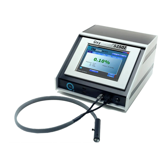
The Permeation chamber is part of OxySense’s OxyPerm line oxygen analysis accessories. OxySense 5000 series instruments are equipped with OxySense’s Gen III software which includes the modules required for capturing oxygen permeation data and calculating the OTR of films reported in either milliliters (cubic centimeters) per square-meter per day... -
Page 6: How It Works
OTR result. Instrumentation Using an OxySense® instrument, one is able to obtain non-invasive (i.e. in-situ) oxygen concentration measurements by way of fluorescence quenching analysis, where, an optical, oxygen-selective sensor (e.g. an OxyDot®) resides within a sealed container, affixed to a transparent surface. -
Page 7: Test Parameters
Permeation Chamber User’s Manual Page 3 2.3.1 Test Parameters The key parameters that must be known prior the test are 1) the oxygen concentration in the driving well, 2) the surface area of the film exposed to the sensing well, and 3) the volume of the sensing well. -
Page 8: Equipment, Material And Supplies
Page 4 Equipment, Materials and Supplies The following list gives the equipment, materials and supplies needed to perform OTR determination using the OxySense® Permeation Chamber. All items are required for a test except for those that are optional as noted. Equipment OxySense®... -
Page 9: Permeation Chamber Overview
Permeation Chamber User’s Manual Page 5 Permeation Chamber Overview The permeation chamber is assembled and tested at the OxySense manufacturing facility. The following diagram depicts the permeation chamber and its assembled components. Serial Number Reading Pen (top view) Insertion Locking Bolts... -
Page 10: Figure 4-2: Permeation Chamber Diagram (Interior)
Permeation Chamber User’s Manual Page 6 Sensing Well Driving Well xyDot® Sensing Well Outlet Sensing Well Inlet Driving Well Outlet Driving Well Inlet (interior view) Figure 4-2: Permeation Chamber Diagram (Interior) Copyright © Industrial Physics Product Integrity 2020... -
Page 11: Gas Cylinders And Flow Meters
0.05 liters per minute (L/min) (0.1 Flow Meter standard cubic-feet per hour (SCFH)). A flow meter may be procured from OxySense or a gas supply retailer. The following figure depicts the connections between a nitrogen cylinder (99.99+% pure), a flow meter, and a permeation chamber. -
Page 12: Otr Determination -Test Setup
Permeation Chamber User’s Manual Page 8 OTR Determination – Test Setup Film OTR is determined by placing a film sample in the permeation chamber, purging the sensing well with nitrogen (99.99+% pure), having a known concentration of oxygen in the driving well (either ambient or 100%), and collecting data over time. - Page 13 Permeation Chamber User’s Manual Page 9 Step 3: Place the chamber on your working surface so that the interior of the chamber is facing up. Step 4: Obtain a tube of vacuum grease. Using your fingers or a dull, non-abrasive utensil (e.g. a swab), create a thin ring of grease around the outer perimeter of the sensing well.
-
Page 14: Purging The Sensing Well
Permeation Chamber User’s Manual Page 10 Step 5: Center and place the film sample over the sensing well. Be sure that the film is positioned such that there will be no gaps between the o-ring of the bottom-side of the chamber and the edges of the film. - Page 15 Permeation Chamber User’s Manual Page 11 IMPORTANT: If you have not yet calibrated the O xyDot®, proceed to Appendix xyDot® Calibration. After calibrating the O xyDot® you may proceed to Section 5.3 Purging the Driving Well Sensing Well Purging Steps: Step 1: Be sure that there is film in the chamber.
-
Page 16: Purging The Sensing Well (Optional)
Permeation Chamber User’s Manual Page 12 Step 5: Connect the outlet of the flow meter to the inlet valve of the top half of the permeation chamber using a length of ¼” gas tubing and tubing connectors with ferrules. Allow the gas to flow through the top of the chamber for 60 seconds. - Page 17 Permeation Chamber User’s Manual Page 13 IMPORTANT: Be sure to consult your organization’s Health and Safety director before acquiring and using concentrated oxygen in your facility. Be sure to comply with all local or state safety regulations. If you plan to use atmospheric oxygen (i.e. air) in the driving well, you may skip this section and proceed to Section 7.0.
- Page 18 Permeation Chamber User’s Manual Page 14 Step 5: Connect the outlet of the flow meter to the inlet valve of the top half of the permeation chamber using a length of ¼” gas tubing and tubing connectors with ferrules. Purge the driving well for at least 4 minutes at 0.05 L/min (0.1 SCFH) Step 6: Close the valves to the driving well in the following sequence:...
-
Page 19: Data Acquisition
Data Acquisition After setting up the permeation chamber for use in the film permeation test, you may proceed to acquire data using the OxySense® 5000 Series instrument and the Gen III Software. As stated in Section 2.0 How It Works, the film permeation test is carried out by monitoring and recording the incremental increase in oxygen concentration in the sensing well over time. - Page 20 Permeation Chamber User’s Manual Page 16 Open Button Browse Active Button Browse All Button View Log File Button View Graph Button Capture Button Setup Button Timer Button Print Report Button End Test Button Chamber Serial Number Box Test Name Box Opens the current test for the permeation chamber with the serial number specified in the Chamber Serial Number box.
- Page 21 Permeation Chamber User’s Manual Page 17 Opens the OTR screen and displays a data plot of the recorded oxygen View Graph values over time for the active test associated with the specified permeation chamber, respectively. Records a data point to the active test associated with the specified Capture permeation chamber.
- Page 22 Permeation Chamber User’s Manual Page 18 Data Display Options Test Identifiers OTR Result Data Display Area Calibration Factors X-Axis Options Select Log Button Timer Interval Options Delete Data Point Button Capture Button Setup Button Timer Button Print Report Button End Test Button Allows you to select what information to display in the Data Display Area.
- Page 23 Permeation Chamber User’s Manual Page 19 The box where data for the test is displayed in either tabular or graphical Data Display format. The format of the data in the box in selected from the data display options. Displays the dA and dB values for the O xyDot®...
-
Page 24: Creating A Permeation Test File
OxySense Gen III software’s database. Steps for Creating a Test File Step 1: With the OxySense Gen III software running, click on the Film Permeation tab. Step 2: Enter the serial number of the film permeation chamber by using a keyboard attached to the instrument, the on-screen keyboard in the software, or by scanning the chamber’s bar... - Page 25 Permeation Chamber User’s Manual Page 21 Step 4: When prompted to add a new test, click Yes. Step 5: The Add New Test window will appear. You must enter the appropriate information in all boxes with the exception of the Test Description box, which is optional. Once you have filled out the text boxes, click Add.
-
Page 26: Configuring Test Parameters
Steps to Configuring Test Parameters Step 1: With the OxySense Gen III software running, click on the Film Permeation tab. You will see the Oxygen Permeation Tests screen. If the test you wish to setup is already open, you may click the Setup button and skip to Step 4. - Page 27 Open button. Step 3: You will see the OTR screen. Click Step 4: Setup Password window will the Setup button appear. Enter the password oxysense and click Copyright © Industrial Physics Product Integrity 2020...
- Page 28 Permeation Chamber User’s Manual Page 24 Step 5: You will see the Setup window. The following table gives a list of items that can be configured in the Setup window. You do not have to make changes to the values in the Setup screen if they are correct. If you made changes to the test setup, click OK.
-
Page 29: Acquiring Data
Steps to Acquiring Data Step 1: Open the test you wish to add data to. With the OxySense Gen III software running, click on the Film Permeation tab. You will see the Oxygen Permeation Tests screen. If the test you wish to setup is already open, you may click the Setup button and skip to Step 5. -
Page 30: Time Intervals
The following are the rules-of-thumb that should be applied when performing a film permeation test by dynamic accumulation using an OxySense 5250i instrument and an OxySense Permeation Chamber: The absolute oxygen concentration difference between data points should be 0.15% or •... -
Page 31: Frequently Asked Questions Aout Time Intervals
Permeation Chamber User’s Manual Page 27 20.8% Oxygen In 100% Oxygen In Driving Well Driving Well Estimated Time Suggested Time Estimated Time Suggested Time for Test Between Each for Test Between Each (mL/m /day) Completion Measurement Completion Measurement 120 days 30 days 28 days 7 days... -
Page 32: Using The Timer Feature
Permeation Chamber User’s Manual Page 28 If I don’t know the OTR of my film, how do I know how much time to wait before taking the next data point? If an estimated or expected OTR of a film is unknown, the time interval must be determined by data monitoring. - Page 33 Permeation Chamber User’s Manual Page 29 Step 3: Before starting the timer, it is best to display the OTR Graph while the timer is running. This allows you to monitor the stability of the rate of permeation. Click on the select button next to OTR in the Graph row of display options.
-
Page 34: Data Analysis
Permeation Chamber User’s Manual Page 30 Data Analysis In order to determine the progress of the test and when the test has ended, you will need to learn how to interpret the Data Quality Indicators available to you in the OTR screen. The four main data quality indicators are listed below. -
Page 35: The Oxygen Graph
Permeation Chamber User’s Manual Page 31 choose a scale with smaller increments than the time interval. For example, if the data points were captured every 3 hours, set the X-Axis to minutes. Select the X-Axis scale by clicking the desired selection box from the X-Axis options. 8.1.2 The Oxygen Graph The oxygen graph depicts the oxygen concentration over time. -
Page 36: Data Interpretation
Page 32 Data Interpretation When performing OTR by DA using OxySense instrumentation, you will find that certain materials, especially those that exhibit a relatively high barrier, will not begin to transmit oxygen immediately. This is due to the physical properties of the film. At the beginning of a test, oxygen ingress in to the sensing well has not yet occurred. -
Page 37: Rejecting Data
When performing OTR by DA and capturing data to the OxySense® Gen III software, it may be necessary to reject data points from the beginning of the data table or the end of the data table and only under the following conditions: 1. - Page 38 Permeation Chamber User’s Manual Page 34 Step 3: Click the Delete Data Point button. You will be prompted to confirm the deletion. Click Yes to confirm. IMPORTANT: process deleting a data point is irreversible. You may wish to back up a copy of the Gen III database prior to rejecting data.
-
Page 39: Troubleshooting
Permeation Chamber User’s Manual Page 35 10.0 Troubleshooting The following examples illustrate scenarios that one may observe throughout the course of a package permeation test. An explanation of the observations and recommended solutions are provided: Scenario 1 Observation: The OTR is negative, or the OTR keeps going up and down. Common The test is in the conditioning phase. -
Page 40: Technical Support
Permeation Chamber User’s Manual Page 36 11.0 Technical Support For technical support, contact Industrial Physics Product Integrity PiSupport@industrialphysics.com Email: +1 (978) 772.2048 Phone: Copyright © Industrial Physics Product Integrity 2020... -
Page 41: Xydot® Calibration
Be sure that there is film in the chamber. If you have not placed film in the chamber, please go to Section 6.1 Placing Film in the Chamber Step 2: Turn on the OxySense 5250i instrument and allow the system to warm up for 30 minutes. Step 3: If it has not already running, launch the OxySense Gen III Software. - Page 42 Permeation Chamber User’s Manual Page A-2 Step 4: Perform the background correction when prompted. You may use the O xyDot® in the permeation chamber to perform the second step of the back ground correction. Step 5: Obtain the High Calibration Point: Ensure that both of the valves on the top of the chamber are fully open.
- Page 43 Permeation Chamber User’s Manual Page A-3 Step 6: Obtain the Low Calibration Point: Ensure that both of the valves on the top of the chamber are fully open. Ensure that the reading pen is inserted properly in the top of the chamber. Ensure that the alignment marker on the chamber is aligned with the alignment marker on the reading pen.
- Page 44 Permeation Chamber User’s Manual Page A-4 (Step 6 cont’d) Connect the outlet of the flow meter to the inlet valve of the top half of the permeation chamber using a length of ¼” gas tubing and tubing connectors with ferrules. Monitor the oxygen concentration displayed on the instrument.
- Page 45 Permeation Chamber User’s Manual Page A-5 Step 7: Close the valves to the sensing well in the following sequence: Close the inlet valve first and then quickly close the outlet valve. IMPORTANT: You must close the inlet valve and then the outlet valve in that order. If you close the outlet valve before the inlet valve, the sensing well will pressurize causing the film in the chamber to distort, bulge and possible...
- Page 46 Permeation Chamber User’s Manual Page A-6 Step 12: Proceed to one of the following sections: If you plan to use ambient oxygen in the driving well, proceed to section 7.0 If you plan to purge the driving well with 100% oxygen, proceed to Section 6.3 Copyright ©...
- Page 47 NOTE: The surface area of the film used in this equation is the area that is exposed to the sensing well and is equal to the cross-sectional area of the sensing well. In an OxySense® Permeation Chamber, the surface area is 0.001676 m...
- Page 48 Permeation Chamber User’s Manual Page B-2 The calculated AOR is defined as the exponent that gives the quotient of volume of accumulated oxygen over the maximum potential accumulated volume and is both time and barrier dependent. ⎛ ⎞ − ⎜ ⎟...
Need help?
Do you have a question about the OxyPerm 5250i and is the answer not in the manual?
Questions and answers