Advertisement
Quick Links
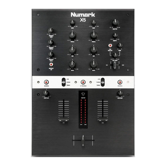
MIC – AUX GAIN" (Microphone – Auxiliary Gain): This knob
adjusts the volume of both the main microphone and auxiliary
inputs.
"Treble " (Microphone – Auxiliary High EQ):This knob adjusts
the high-tone input sound of the microphone.
"Bass" (Microphone – Auxiliary Low EQ): This knob adjusts
the low-tone input sound of the microphone.
"Gain knob" (Input Level Trim): This rotary control adjusts the
pre - fader input signal levels of the inputs.
EQ:
"Treble" (Input Level High EQ): This rotary control adjusts the
high – tone sound of the inputs.
"Middle" (Input Level Midrange EQ): This rotary control adjusts
the high-tone sound of the inputs.
"Bass" (Input Level Low EQ): This rotary control adjusts the
high – tone sound of the inputs.
"Phono(AUX)/Line Switch" (Input Selector Switch): These
three – position toggles select what input source is engaged among
the connected units and a flash position to allow rapid transforming
effect.
"Input Level Slider" (VCA Fader): These slide faders adjust the level
for CH-1 or CH-2 respectively.
"Slope knob" (Input Fader Curve Style Control): The position of this
knob determines the rate of volume level increase of the fader.
"Reverse Button" (Input Fader Reverse Control): Activation of this
switch can reveres the fader direction.
"Program/PFL Level Meter and Button": Press to alternate display
modes.
"Cue Gain Knob"(Headphone Level): This rotary control adjusts
the levels of the headphones connected to the front panel input.
"Cue Tone Knob" (Headphone Tone Control): This rotary knob
adjusts the tone of the headphone output.
"Channel Cue Slider": Channels 1 and 2 can be previewed using this
mini – crossfader.
"Cue Button" (MIC and MASTER Cue Buttons): When pressed,
the CUE button illuminates green indicating that the source is
being cued to the headphones.
"Crossfader Slider" (Digital VCA Crossfader): This slide fader
blends audio between CH-1 and CH-2.
SERVICE MANUAL
SPECIFICATIONS
"Contour Knob" (Crossfader Rate/Slope Control): The position of this switch
determines how quickly or intensely the crossfader will act depending upon mode
setting.
"Direction Button" (Crossfader Reverse Control): Activation of this switch
reverses the assignment of CH-1 and CH-2 on the crossfader.
"Master Knob" (Main Output Level Control): This rotary control adjusts the main
output volume.
"Booth Knob" (Master/Split Style Headphone Cueing Switch): This rotary control
adjusts the auxiliary (AKA booth) output volume.
"Digital Output" (Optical): 48kHz, 24-bit S/PDIF output.
"Digital Output" (Coax): 48kHz, 24-bit S/PDIF output.
MODEL:
X5
Advertisement

Related Manuals for Numark X5


Summary of Contents for Numark X5
- Page 1 SERVICE MANUAL MODEL: SPECIFICATIONS MIC – AUX GAIN” (Microphone – Auxiliary Gain): This knob “Contour Knob” (Crossfader Rate/Slope Control): The position of this switch adjusts the volume of both the main microphone and auxiliary inputs. determines how quickly or intensely the crossfader will act depending upon mode “Treble “...
-
Page 2: Disassembly Procedures
DISASSEMBLY PROCEDURES 1. REMOVING OF THE TOP PANELS (Fig1) (A) REMOVE 4 CAPS. (B) REMOVE 17 SCREWS BEFORE REMOVING OF THE TOP PANELS, INCLUDED UPPER, MIDDLE AND LOWER PANEL. (Fig1) - Page 3 2. REMOVING OF THE BOTTOM CHASSIS (Fig2). (A) REMOVE 12 SCREWS BEFORE REMOVING OF THE BOTTOM CHASSIS. (Fig.2) 3. REMOVING OF THE REAR PANEL AND DISASSEMBLE THE I/O PCB ASSEMBLY. (Fig3). (A) REMOVE 13 SCREWS. (B) REMOVE 2 NUTS TO DISSEMBLING THE REAR PANEL AND THE I/O PCB ASSEMBLY. (Fig.3)
- Page 4 3-1.DISASSEMBLE THE I/O PCB ASSEMBLY . (Fig.3-1) (A)(B)(C)(D)(E)(F)(G)(H)REMOVE 9 CABLES. (Fig.3-1) 4. REMOVING OF THE FRONT PANEL (Fig4). (A) REMOVE 1 KNOB. (B) REMOVE 2 SCREWS BEFORE MOVING OF THE FRONT PANEL.. (Fig.4)
- Page 5 4-1. DISASSEMBLE THE MIC AND PHONE PCB ASSEMBLY . (Fig.4-1) (A) REMOVE 2 NUTS AND 2 WASHERS BEFORE REMOVING OF THE MIC AND PHONE PCB ASSEMBLY. (B) REMOVE 2 CABLES ON THE MIC AND PHONE PCB ASSEMBLY. (Fig.4-1) 5. REMOVING OF THE MAIN PCB ASSEMBLY. 5-1.
- Page 6 5-2. REMOVING OF THE NUTS, WASHERS AND VELVET CARPETS ON THE CABINET . (Fig.5-2) (A) REMOVE 14 NUTS AND 14 WASHERS. (B) REMOVE 2 VELVET CARPET. (C) REMOVE 10 SCREWS. (Fig.5-2) 5-3. REMOVING OF THE VR PCB ASS’Y . (Fig.5-3) (A) REMOVE 8 SCREWS.
- Page 7 5-4. DISASSEMBLE THE SWITCH PCB ASSEMBLY AND REMOVING OF THE FADERS . (Fig.5-4) (A) REMOVE 2 KNOBS. (B) REMOVE 4 SCREWS. (C) REMOVE 2 METAL PLATE. (D)REMOVE 2 CABLES ON SWITCH PCB ASSEMBLY. (E)(F)(G)REMOVE 3 CABLES CONNECTED TO THE FADERS BEFORE REMOVING OF THE FADERS. (Fig.5-4) 5-5.
-
Page 8: Wiring Diagram
WIRING DIAGRAM... -
Page 9: Explode Diagram
EXPLODE DIAGRAM NMS9MAR01/02/03/04/05/06/07 SEQUENCE NO OF EXPLODE DIAGRAM WILL BE MARKED ON REF. COLUMN OF BOM LIST... -
Page 10: Packing Diagram
PACKING DIAGRAM NMS9MAR01... - Page 11 PACKING DIAGRAM NMS9MAR02...
- Page 12 PACKING DIAGRAM NMS9MAR03...
- Page 13 PACKING DIAGRAM NMS9MAR04/05/06/07...
- Page 14 NMS9MAR01~07 BOM LEVEL DESCRIPTION 0.1 CN0820003006 Flat Cable 8Pin Pitch 2.0mm Single row length 300mm 0.1 K46-1 Cable Tie 0.1 LAC62MAR631 Date Label 0.1 LAC22MAR398 SERIAL LABEL 0.1 LAC62MAR399 BAR COADE LABEL 0.1 LAC62MAR492 Bar Code Label 0.1 LAC63MAR410 SAFETY LABEL 0.1 LAC67YAH261 Sticker φ8mm Green 0.1 MT0705517...
- Page 15 0.1 RU1330701 FOOT STAND 0.1 SC0204BIPI Screw 0.1 SC0305PIBI Screw 0.1 SC0308ABBI Screw(FLAT) 0.1 SC0308ABNI Screw 0.1 SC0308PBBI Screw M3x8mm PPB TAPPING 0.1 SC0308RBNI Screw M3*8mm Prn Tapping 0.1 SC0312RBNI Screw 0.1 SC2604RIBI SCREW 0.1 SC2606RBNI SCREW 0.1 SP1110603 SPRING 0.1 TF48093201UL ADAPTOR 9VAC 1.3A UL (01) TF48093301EU...
- Page 16 PC02C035 I/O PCB 2Layer FR-4 1.6T 208*136.5MM RJ1106-09 RCA BASE 2P RJ1107-09 RCA BASE 4P J1~3 RS000008J05 RESISTOR 0Ω 5% SMD 0805 R149,150 RS001M08F05 RESISTOR 1M 1% SMD 0805 RS002K08F05 RESISTOR 2K 1% SMD 0805 R74,108,110,111,113 RS010008F05 RESISTOR 100Ω 1% SMD 0805 R2,5,10,13,23,40~43,66,67,123,140 RS010K08F05 RESISTOR 10K 1% SMD 0805...
- Page 17 ...3 RS004708F05 RESISTOR 47Ω 1% SMD 0805 R6,9 ...3 RS010008F05 RESISTOR 100Ω 1% SMD 0805 R4,5 ...3 RS010K08F05 RESISTOR 10K 1% SMD 0805 R2,7,8,10,11,13,16,17 ...3 RS015008F05 RESISTOR 150Ω 1% SMD 0805 ...3 RS3K3208F05 RESISTOR 3.32K 1% SMD 0805 ...3 SW-150 POWER SWITCH S3~7 ...3 SWSKHVBE3520...
- Page 25 J01MNB03A.sch-1 - Mon Apr 30 16:36:00 2007...
- Page 26 J01MNB03A.sch-2 - Mon Apr 30 16:36:01 2007...
Need help?
Do you have a question about the X5 and is the answer not in the manual?
Questions and answers