
Related Manuals for FLIR M500


Summary of Contents for FLIR M500
- Page 1 Operator’s Manual M500 This document does not contain export-controlled information...
- Page 2 © 2020 FLIR Systems, Inc. All rights reserved worldwide. No parts of this manual, in whole or in part, may be copied, photocopied, translated, or transmitted to any electronic medium or machine readable form without the prior written permission of FLIR Systems, Inc.Names and marks appearing on the products herein are either registered trademarks or trademarks of FLIR Systems, Inc.
-
Page 3: Table Of Contents
Park Mode ..................13 The Bootup Process ................13 Powering the Camera..............13 Powering the JCU II..............14 JCU II Power Menu ................14 Standby States................14 M500 Joystick Control Unit Introduction..................16 JCU II Joystick..................16 Tilting the Camera ................16 Rotating the Camera ..............16 Zooming the Camera..............16 JCU II Buttons ..................17... - Page 4 Color Button—IR Imaging only ..........18 Focus Buttons ................18 Camera Button ..............18 User Buttons ................18 Display Camera and JCU II IP Address .........19 Button Summary................19 M500 System Configuration Overview ....................20 Main Menu..................20 Immediate Action Menu Buttons...........21 Tracker: .................21 Park camera: .................21 InstAlert/Exit InstAlert mode: ..........21...
- Page 5 Radar target (TTM): ...............31 Video Tracking Mode Overview ...................32 Joystick Operation ................34 Video Tracker Errors ................34 Online Tracker Help................35 M500 Reference Information Introduction..................36 Acronyms ...................36 List of Icons ..................37 System Specifications ................40 Troubleshooting Tips ................41 Video not displayed on monitor ..........41 Cleaning ................41...
- Page 6 Contents Multiple Cameras and/or JCU IIs on a single network ...42 432-0012-01-10 Version 110 August 2020...
-
Page 7: M500 Overview
M500 Overview General Information This manual describes the operation of the M500 cameras. If you need help or have additional questions, please call to speak with our support experts; refer to contact information listed on the back cover of this manual. -
Page 8: Documentation Conventions
Caution: Be careful not to leave fingerprints on the M500 optics. Caution: The M500 requires a power supply of 12 Vdc to 24 Vdc nominal, 5.5 A maximum @ 24 Vdc, 11 A maximum @ 12 Vdc. Absolute voltage range: 12 Vdc to 32 Vdc. Operating the system outside of the specified input voltage range or the specified operating temperature range can cause permanent damage. -
Page 9: System Description
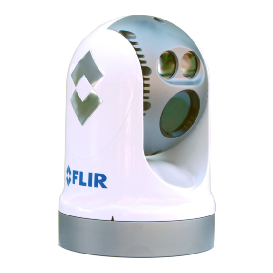
System Description System Description The multi-sensor M500 is a stabilized maritime thermal and high definition (HD) visible-light camera system for use on most types of vessels. The mid-wave infrared (MWIR) thermal camera with 14X optical zoom provides excellent nighttime visibility and situational awareness, without any form of natural or artificial illumination. -
Page 10: M500 Components
• Main camera body, also known as the pan/tilt camera unit • Joystick Control Unit (JCU II), compatible with the MU, MV, M400, and M500 camera systems • Ethernet switch with power over Ethernet (PoE) to power the JCU II and network to the camera •... -
Page 11: Thermal Video Display
OSD menu that is shown when the Menu button is pressed. Using the menus is described in “M500 System Configuration” on page 20. A complete list of all of the icons used in the system and a brief description of how they are used can be found in “List of Icons”... -
Page 12: Position Indicator Icons
Thermal Video Display Position indicator icons The azimuth position indicator shows the direction the camera is pointing relative to the vessel. The shaded triangle shows the approximate camera field of view (FOV). The elevation position indicator shows the vertical tilt of the Azimuth Elevation camera above or below the horizontal plane of the vessel. -
Page 13: M500 System Startup
M500 System Startup System Startup and Shutdown The M500 camera does not have an on/off switch. Instead, its power state is controlled by the JCU II. Generally, the camera is never completely off but in a Park mode or standby state waiting for a “wake”... -
Page 14: Powering The Jcu Ii
ID, Select camera such as M500. When more than one camera is found on the network, the JCU II attempts to reconnect to the last camera it was connected to, or if it has not connected to a camera, it will prompt the user to select a camera. - Page 15 JCU II Power Menu option from the menu. The menu options available will reflect the available hardware on the camera network. • JCU Stndby?—select to power down the JCU II. • Camera Stndby?—select to power down the camera, leaving the JCU II powered to connect to a different camera.
-
Page 16: M500 Joystick Control Unit
M500 Joystick Control Unit Introduction The Joystick Control Unit (JCU II) is the primary method of controlling the M500 camera. Use it to move the camera, zoom the camera, switch between infrared and visible-light cameras, adjust image settings, and access the on-screen menus. -
Page 17: Jcu Ii Buttons
Menu Button Press the Menu button to access the system on-screen-display (OSD) menus. In most cases, there is no need to modify the factory default configuration settings of the system. Refer to “M500 System Configuration” on page 20. When the OSD menu is shown, use the joystick up, down, left, and right to navigate through the menu entries. -
Page 18: Scene Button-Ir Imaging Only
JCU II Buttons Scene Button—IR imaging only The M500 thermal sensor automatically adjusts to changing conditions providing optimized high-contrast images. The preset automatic gain control (AGC) settings offer the most balance and image quality for specific conditions. Experiment with the different settings to find out which settings work best in different conditions. -
Page 19: Display Camera And Jcu Ii Ip Address
JCU II Buttons Display Camera and JCU II IP Address Press the Color button while pushing the joystick forward; the IP address of the JCU II and then the camera will display on the JCU II screen. Button Summary Table 3.1 summarizes the action of each button on the JCU II. Summary of Button Actions TABLE 3.1 Button... -
Page 20: M500 System Configuration
Overview This chapter describes how to configure the system options using on-screen-display (OSD) menus. Operating the M500 camera does not require modifying any of the factory configuration settings. However, the OSD menus allow setting the following: • Choose configuration options that match personal preferences such as Joystick Mode or default color scheme. -
Page 21: Immediate Action Menu Buttons
Home button. The camera will return to Home position. The Park position can be reconfigured by an admin user through the web browser interface. See the M500 Installation Guide. InstAlert/Exit InstAlert mode: When the camera is placed in InstAlert mode, a special search palette is invoked so that a set percentage of the hottest temperatures in the image are highlighted in Red-Orange shades, while colder temperatures are all in shades of gray. -
Page 22: Surveillance
Main Menu Surveillance: When the camera is in surveillance mode, it pans continuously left and right, until it is taken out of surveillance mode or until the JCU II is used to move the camera. The camera does not automatically resume panning; enable surveillance again by pressing a programmed User button or selecting it again in the main menu. -
Page 23: Image And Settings Configuration Menus
Main Menu Image and Settings Configuration Menus The final three main menu buttons provide choices for system settings and information. End of menu symbol Menu will loop to the other end Image... See “Image Menu” on page 24. Settings… See “Settings Menu” on page 25. Help…... -
Page 24: Image Menu
Image Menu Image Menu When Image is selected from the main menu, the following OSD menu items are shown. Polarity—IR camera only: Inverts the colors representing hot and cold in the infrared imagery. When using the IR camera the color palettes described below are available. -
Page 25: Vis Low Light Mode
Settings Menu Color Palette Polarity Inverted Redscale Red-Hot Red-Cold Fusion Fusion Fusion-Invert VIS low light mode: On/Off Select this option to turn On/Off VIS low light mode. This function works in conjunction with the setting of the Advanced image low light mode (refer to “Advanced Image Menu”... -
Page 26: Surveillance
Set Az & El zero reference: Icons on the video show the direction the camera is facing in relation to an outline of a ship. The M500 camera has a “forward” direction adjustment which has been set at the factory. After the camera is installed, both the azimuth and elevation should be set to account for variations required during installation so that the icons on the video show the expected angular position of the camera. -
Page 27: Advanced Image Menu
Settings Menu Advanced Image Menu IR eZoom, VIS eZoom: (On/Off) The IR camera will extend past the 14x optical zoom with an additional 8x eZoom (to 112x). After the lens reaches the maximum optical zoom, eZoom the zoom scale shown on the display changes as shown at the right. The scale will change back to 14x when the eZoom is decreased to zero. -
Page 28: Instalert Highlight, Icealert Highlight
Selecting Minimal turns off most of the on-screen icons except when their corresponding controls are actively in use. The pan position (azimuth) icon, tilt (elevation) position icon, and the FLIR logo are always displayed. Other icons such as home and scene display on the screen only momentarily when they are changed. -
Page 29: Help Text
Additional information regarding the protocol can be found on the NMEA Web site: http://www.nmea.org/content/nmea_standards/nmea_standards.asp. When NMEA is being used, the M500 acts as a listener and receives messages from the main control unit that is monitoring various sending devices in the system, such as radar, GPS, or independent input ports. -
Page 30: Nmea Settings
Additional settings such as target dwell time affect how the messages are processed. Dwell time determines how long the camera remains on a particular target. The ability of the M500 to accurately track a target depends on the quality of the data sent from the radar unit. -
Page 31: Next Waypoint (Bwc)
Icon Display Mode. While it is possible to select up to 100 targets to be tracked by M500 (refer to the radar or GPS documentation on how to designate a target), typically the operator selects five or less. Once targets are selected, the camera will point toward each sequentially, and track it using position data sent from the radar unit. -
Page 32: Video Tracking Mode
Video Tracking Mode Overview To enable Video Tracking mode press the right joystick button; a tracking box is shown on the video. Manually center the target in the tracking box by pointing the camera using the joystick. Press the right joystick button again to engage the target and begin tracking. When a target is selected, the tracking box is no longer shown and the Tracking icon is shown on the display. - Page 33 Overview Tracking state—When the target is acquired, the acquisition gate disappears and the tracking icon is shown. To show the tracking box after engaging a target, select show tracking box (refer to “Tracker:” on page 21). Tracking icon Joystick Buttons: Left - Cancel tracking Figure 5-2: Video Tracking Mode—Tracking state Seeking state—In the seeking state, orange cross-hairs will be shown within the acquisition gate and flash at 2 Hz, while trying to acquire the target.
-
Page 34: Joystick Operation
Joystick Operation Joystick Operation When the Video Tracking mode is enabled by pressing the right joystick button, the behavior of the joystick changes so that tracker-specific features can be controlled. When acquiring a target, use the JCU II to: • Point the camera at the area containing a possible target (normal pan and tilt joystick operation). -
Page 35: Online Tracker Help
Online Tracker Help Online Tracker Help Refer to the Tracker tab on the OSD Help / User guide page (shown) for instructions on using the video Tracking mode. • The Tracking mode is enabled by selecting the right joystick button. •... -
Page 36: M500 Reference Information
M500 Reference Information Introduction This chapter includes a glossary of acronyms, a list of symbols used in on-screen-display (OSD), and a number of lists and tables that summarize system information and show how features vary by camera model. It also includes a set of tips for troubleshooting issues. -
Page 37: List Of Icons
List of Icons Acronyms TABLE 6.1 Acronym/Term Definition NTSC National Television System Committee on-screen-display Pan/Tilt Phase Alternating Line Power over Ethernet SCTE Society of Cable Telecommunications Engineers Software Developer’s Kit UPnP Universal Plug and Play Volts, Direct Current Visible (visible-band camera reference) List of Icons Table 6.2 lists the icons that may be shown on the screen during various operations, with a brief description of their meaning. - Page 38 List of Icons Video Display Icons (Continued) TABLE 6.2 Icon Name Description Elevation (Tilt) Shows the vertical tilt of the camera. The shaded triangle shows the approximate camera position. Focus Scale Shown when autofocus is invoked to indicate the progress of the operation.
- Page 39 List of Icons Video Display Icons (Continued) TABLE 6.2 Icon Name Description NMEA TTM Receiving NMEA messages using the NMEA Tracked Target Message Message (TTM) sentence format has been enabled; this is also known as radar tracking The camera is shutting down. Power down Scene: Night One of four scene presets (automatic gain control settings)
-
Page 40: System Specifications
System Specifications System Specifications Table 6.3 lists details about physical characteristics, power usage, and environmental features of the M500 camera. Specifications TABLE 6.3 Physical Characteristics Camera Size 32.4 cm (12.75 in) diameter by 46 cm (18.1 in) tall Camera Weight 12.22 kg (27 lb), depending on the camera model... -
Page 41: Troubleshooting Tips
If the camera still does not produce an image, contact the FLIR dealer or reseller who provided the camera, or contact FLIR directly (contact information is provided on the rear cover of this manual). -
Page 42: Image Too Dark Or Too Light
Image too dark or too light By default, the M500 thermal camera uses an automatic gain control (AGC) setting that has proven to be superior for most applications. However, a specific environment may benefit from a different AGC setting. - Page 43 FLIR Systems, Inc. CS World Headquarters FLIR Systems, Inc. 6769 Hollister Ave. Goleta, CA 93117 PH: +1 888 747 3547, Option 5 maritimecamerasupport@flir.com 432-0012-01-10 Rev. 110 August 2020...
Need help?
Do you have a question about the M500 and is the answer not in the manual?
Questions and answers