Advertisement
Quick Links
NAV SD 501 and NAV SD 101 • Setup Guide
This guide provides instructions for an experienced installer to install the Extron NAV SD 501 and
NAV SD 101 scaling decoders and to make all connections. One or more compatible Extron NAV
encoders and one or more decoders form an AV distribution and switching matrix on a managed 1G
IP network.
For more information on any subject in this guide, see the NAV SD 501 and NAV SD 101 User Guide, available at
NOTE:
www.extron.com.
Installation
Step 1 — Mounting
Turn off or disconnect all equipment power sources and rack or furniture mount the decoder as required.
Step 2 — Rear Panel Connections
POWER
12V
2.0 A MAX
H H
H
POWER
12V
2.0 A MAX
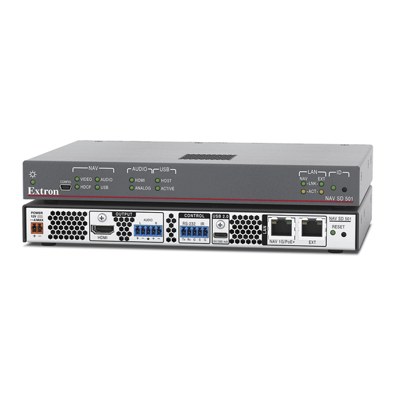
Figure 1.
NAV SD 501 and NAV SD 101 Rear Panel Features
A
NAV 1G/PoE+ port — Connect to an Ethernet LAN on which one or more encoders also reside for streaming and control. This port
can also receive Power over Ethernet (PoE+) to power the decoder (see
B
Extension port (NAV SD 501 only) — If desired, connect another networked device to this port. The port acts as a networked switch
to the NAV 1G/PoE+ port.
NOTE:
The Extension port cannot provide PoE.
C
HDMI output port — Connect an HDMI cable between this port and an HDMI display (or a DVI display, with an appropriate adapter).
See
LockIt® Lacing Brackets
D
AUDIO output port — This 5-pole, 3.5 mm captive screw connector outputs the streamed, unamplified, line level analog audio. Connect
an audio device, such as an audio amplifier or powered speakers (see
E
CONTROL RS-232/IR port — Connect a serial RS-232 signal, a modulated IR signal, or both to this 3.5 mm, 5-pole captive screw
connector for bidirectional RS-232 and IR communication with connected remote controlled devices using an Extron control system
Control connector
(see
F
USB 2.0 port (NAV SD 501 only) — Connect a USB Type-C cable to USB host or a USB device. See
securely fasten the USB connector to the decoder.
This connector is limited to supplying 200 mA in USB device mode.
NOTE:
G
RESET button — This button initiates three modes of reset (see the NAV SD 501 and NAV SD 101 User Guide, available at
www.extron.com, for details).
H
POWER connector (optional) — Plug the included external 12 VDC power supply into this 2-pole connector for local power (see
Power connector
on page 6 to wire the connector and
OUTPUT
AUDIO
L
R
HDMI
C
C C
D
D D
OUTPUT
AUDIO
L
R
HDMI
on page 6 to use the LockIt HDMI Cable Lacing Bracket to secure the connector to the decoder.
on page 6 to wire the connector).
CONTROL
USB 2.0
RS-232
IR
Tx Rx G S G
5V/200 mA
E E
E
F
F F
CONTROL
RS-232
IR
Tx Rx G S G
Power
on page 3 for power options).
Analog audio output
Power
for power options).
NAV SD 501
RESET
NAV 1G/PoE+
EXT
A
A A
B
B B
G
G G
NAV SD 101
RESET
NAV 1G/PoE+
on page 6 to wire the connector).
LockIt® Lacing Brackets
to
1
Advertisement

Subscribe to Our Youtube Channel
Related Manuals for Extron electronics NAV SD 501


Summary of Contents for Extron electronics NAV SD 501
- Page 1 Power over Ethernet (PoE+) to power the decoder (see on page 3 for power options). Extension port (NAV SD 501 only) — If desired, connect another networked device to this port. The port acts as a networked switch to the NAV 1G/PoE+ port.
- Page 2 The port uses IP over USB technology; the IP address is always 203.0.113.22 and CANNOT be changed. The Config port is also discoverable via Extron Toolbelt (see the NAV SD 501 and NAV SD 101 User Guide; the guide and Toolbelt are available for download at www.extron.com).
-
Page 3: System Operation
2)— Indicate the status of the network connections, as follows: • NAV LED (NAV SD 501) or LAN LED (NAV SD 101) — Link LED — Lit steadily indicates that a network link is established. Blinking indicates a link speed less than 1G. - Page 4 NAV SD 501 and NAV SD 101 • Setup Guide (Continued) Press the keyboard <Enter> key. The browser displays a privacy error message (see figure 3 at right for an example in the Chrome browser). Click Advanced (see figure 3, ).
-
Page 5: Connection Settings
1 1 1 1 * NAV SD 501 only Figure 5. Home Page Detailed descriptions of communication, configuration, and monitoring are provided in the NAV SD 501 and NAV SD 101 NOTE: User Guide, available at www.extron.com. Connection settings View and change connection settings as follows: On the home page, click Settings (see figure 5, ) >... -
Page 6: Connection Details
NAV SD 501 and NAV SD 101 • Setup Guide (Continued) Use a Tweeker or other small screwdriver to press and release the encoder front panel ID button. The encoder exits pairing mode. Repeat steps 1 through 4 to pair decoders to other encoders.
Need help?
Do you have a question about the NAV SD 501 and is the answer not in the manual?
Questions and answers