Table of Contents
Advertisement
Quick Links
Advertisement
Table of Contents

Related Manuals for HT JUPITER


Summary of Contents for HT JUPITER
- Page 1 ENGLISH User manual Copyright HT ITALIA 2017 Version EN 1.00 - 03/10/2017...
-
Page 3: Table Of Contents
JUPITER Table of contents: PRECAUTIONS AND SAFETY MEASURES ............... 2 1.1. Preliminary instructions ..................... 2 1.2. During use ......................... 3 1.3. After use ..........................3 1.4. Definition of Measurement (Overvoltage) category ............3 GENERAL DESCRIPTION ................... 4 ... -
Page 4: Precautions And Safety Measures
Only the leads supplied with the instrument guarantee compliance with the safety standards. They must be in good conditions and replaced, if necessary, exclusively with HT original accessories. Do not test circuits exceeding the specified voltage limits. Do not perform any test under environmental conditions exceeding the limits indicated in §... -
Page 5: During Use
JUPITER 1.2. DURING USE Please carefully read the following recommendations and instructions: CAUTION Failure to comply with the caution notes and/or instructions may damage the instrument and/or its components or be a source of danger for the operator. Before activating the rotary switch, disconnect the test leads from the circuit being measured. -
Page 6: General Description
JUPITER 2. GENERAL DESCRIPTION The instrument carries out the following measurements: DC / AC, AC+DC TRMS voltage DC / AC / AC+DC TRMS voltage with low impedance (LoZ) DC / AC / AC+DC TRMS current with standard clamp transducers ... -
Page 7: Preparation For Use
JUPITER 3. PREPARATION FOR USE 3.1. INITIAL CHECKS Before shipping, the instrument has been checked from an electric as well as mechanical point of view. All possible precautions have been taken so that the instrument is delivered undamaged. However, we recommend generally checking the instrument in order to detect possible damage suffered during transport. -
Page 8: Nomenclature
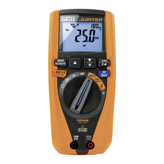
JUPITER 4. NOMENCLATURE 4.1. DESCRIPTION OF THE INSTRUMENT CAPTION: 1. LCD display 2. arrow key 3. Key/ 4. Key MODE/MXMNPK 5. Key H/H%/H 6. Key RCDIN/ 7. Key GO/HOLD 8. Rotary selector switch 9. Input terminal COM 10. Input terminal V L Fig. -
Page 9: Description Of Function Keys
JUPITER 4.2. DESCRIPTION OF FUNCTION KEYS 4.2.1. Key GO/HOLD , and Pressing the key GO/HOLD (for functions V , LoZV ) makes the instrument hold the value of the quantity shown on the display. The message HOLD appears on the “... -
Page 10: Key Mode/Mxmnpk
JUPITER 4.2.3. Key MODE/MXMNPK A simple pressing of key MODE/MXMNPK allows for the following operations: Selection of measuring modes AC+DC in positions V , LoZV “ ” “ ” “ ” Selection of measuring modes AC+DC (see § 4.2.8) in “... -
Page 11: Loz Function
JUPITER 4.2.6. LoZ function This mode allows carrying out AC/DC voltage measurement with a low input impedance, in order to eliminate wrong readings due to parasite voltages for capacitive couplings. CAUTION By plugging the instrument between the phase and earth conductor, because of the low impedance of the instrument during measurement, RCD protections may trip while carrying out the test. -
Page 12: Setting The Rated Voltage In Loop/Ra Measurement
JUPITER 4.2.11. Setting the rated voltage in Loop/Ra measurement To set the value of rated voltage necessary to instrument in order to calculate the assumed short-circuit current in position Ra Loop, proceed as follows: 1. Select the position Ra Loop 2. -
Page 13: Operating Instructions
JUPITER 5. OPERATING INSTRUCTIONS 5.1. DC VOLTAGE MEASUREMENT CAUTION The maximum input DC voltage is 690V. Do not measure voltages exceeding the limits given in this manual. Exceeding voltage limits could result in electrical shocks to the user and damage to the instrument. -
Page 14: Ac, Ac+Dc Voltage Measurement
JUPITER 5.2. AC, AC+DC VOLTAGE MEASUREMENT CAUTION The maximum input AC voltage is 690V to earth. Do not measure voltages exceeding the limits given in this manual. Exceeding voltage limits could result in electrical shocks to the user and damage to the instrument. -
Page 15: Ac, Dc, Ac+Dc Voltage With Low Impedance (Loz)
JUPITER 5.3. AC, DC, AC+DC VOLTAGE WITH LOW IMPEDANCE (LOZ) CAUTION The maximum input AC/DC voltage is 690V to earth. Do not measure voltages exceeding the limits given in this manual. Exceeding voltage limits could result in electrical shocks to the user and damage to the instrument. -
Page 16: Resistance Measurement And Continuity Test
JUPITER 5.4. RESISTANCE MEASUREMENT AND CONTINUITY TEST CAUTION Before attempting any resistance measurement, cut off power supply from the circuit to be measured and make sure that all capacitors are discharged, if present. Fig. 11: Use of the instrument for resistance measurement and continuity test 1. -
Page 17: Phase Sequence And Phase Concordance With 1 Terminal
JUPITER 5.5. PHASE SEQUENCE AND PHASE CONCORDANCE WITH 1 TERMINAL CAUTION Input AC voltage to carry out this test must be in range 130V ÷ 690V with a frequency in range 42.5Hz ÷ 69Hz. This test can only be performed by touching the metal parts of the conductors. - Page 18 JUPITER 4. In conditions of correct voltage and frequency, the instrument shows message HOLD “ ” symbols and the buzzer sounds continuously, waiting for a stable voltage “ ” value on phase L1 to be detected (see Fig. 14 left side).
-
Page 19: Overall Earth Resistance Without Rcd Tripping
JUPITER 5.6. OVERALL EARTH RESISTANCE WITHOUT RCD TRIPPING This function is performed in compliance with standards CEI 64-8 612.6.3, IEC/EN61557-6 and allows measuring the impedance of the fault loop, comparable to the overall earth resistance in TT systems (see § 9.2). - Page 20 JUPITER 1. set the value of rated voltage Phase-Earth (see § 4.2.11) 2. Set the limit value of contact voltage (see § 4.2.10) 3. Select position Ra Loop. 4. Press key MODE/MXMNPK and select option RCD Ra “ ” 5. In case the cable with Shuko plug is used, insert the red conductor into input terminal V ...
- Page 21 JUPITER 8. In case no anomalous conditions are present, the instrument carries out the test and symbol flashes on the display. At the end of the test, the following screens appear on the display. Fig. 22: Results of measurement of overall earth resistance 9.
-
Page 22: Measurement Of Line/Loop Impedance
JUPITER 5.7. MEASUREMENT OF LINE/LOOP IMPEDANCE This function is performed in compliance with standards CEI 64-8 612.6.3, IEC/EN61557-3 and allows measuring line impedance, fault loop impedance and the assumed short-circuit current (see § 9.3). The following operating modes are available: ... - Page 23 JUPITER Fig. 24: Use of the instrument for measuring Loop L-PE impedance with leads Fig. 25: Use of the instrument for measuring Loop L-N impedance with cable provided with Schuko plug IT - 21...
- Page 24 JUPITER Fig. 26: Use of the instrument for measuring Loop L-N impedance with leads Fig. 27: Use of the instrument for measuring Loop L-L impedance with leads 1. Set the value of rated phase-to-earth, phase-to-neutral or phase-to-phase voltage (see § 4.2.11) 2.
- Page 25 JUPITER 6. For Loop L-PE measurements, in case measuring leads are used, insert the red conductor into input terminal V L and the black conductor into input terminal COM/E/N and connect the instrument to the system to be tested (see Fig. 24). The value of voltage Phase-Earth is shown on the display 7.
-
Page 26: Test On A And Ac Rcds
JUPITER 5.8. TEST ON A AND AC RCDS This function is performed in compliance with standard IEC/EN61557-6 and allows measuring the tripping time and the current of the instant general RCDs of the system (see § 9.1). The following operating modes are available: ... - Page 27 JUPITER Fig. 30: Use of the instrument for RCD test on single-phase system with leads Fig. 31: Use of the instrument for RCD test on three-phase system with leads IT - 25...
- Page 28 JUPITER 1. Set the limit value of contact voltage (see § 4.2.10) 2. Select position RCD 3. Press key MODE/MXMNPK and select one of the following options: Mode AUTO RCD T Measurement of the RCD s tripping time in automatic ’...
- Page 29 JUPITER 10. The first test carried out is the one with test current In and polarity 0°. The result of partial measurement is shown on the display with indication NOT OK (see Fig. “ ” “ ” left side). Symbol flashing indicates that the RCD must be reset.
- Page 30 JUPITER Tripping time in manual mode (test current In) Fig. 35: Tripping time in manual mode at In 10. The correct measurement result is shown on the display (see Fig. 35 left side) with – indication “ ” 11. The correct measurement result is shown on the display (see Fig. 35 right side) with –...
-
Page 31: Dc, Ac, Ac+Dc, Inrush Current With Clamp Transducers
The instrument carries out the measurement both with flexible clamp transducer (optional accessories) and with other standard clamp transducers in the HT family (optional accessories). With transducers having an Hypertac output connector, the optional adapter NOCANBA is necessary to obtain the connection. - Page 32 JUPITER 6. For standard clamp transducers, press key MODE/MXMNPK to select “ ” “ ” AC+DC measurement. Anyway, the instrument automatically recognizes AC or DC “ ” quantities. 7. Insert the red cable into input terminal V L and the black cable into input terminal COM/E/N.
- Page 33 The instrument carries out the measurement both with flexible clamp transducers (optional accessories) and with other standard clamp transducers in the HT family (optional accessories). For inrush current with high DC component is recommended the use of AC/DC clamps.
- Page 34 JUPITER 9. Upon recognition of the event, measurement stops automatically and the instrument shows, in its main display, the Max RMS value calculated according to the evaluation time of 100ms (default) indicated on the secondary display (see Fig. 43 right side) –...
-
Page 35: Maintenance
JUPITER 6. MAINTENANCE CAUTION Only expert and trained technicians should perform maintenance operations. Before carrying out maintenance operations, disconnect all cables from the input terminals. Do not use the instrument in environments with high humidity levels or high temperatures. Do not expose to direct sunlight. -
Page 36: Technical Specifications
JUPITER 7. TECHNICAL SPECIFICATIONS 7.1. TECHNICAL CHARACTERISTICS Accuracy calculated as [%reading + (no. digits*resolution)] at 23°C 5°, <80%HR DC Voltage (Autorange) Range Resolution Input Accuracy Overload protection impedance 0.0 690.0 (0.5%rdg + 2digits) 1M 690VDC/ACrms AC, AC+DC, LoZ TRMS Voltage (Autorange) - Page 37 JUPITER Harmonic voltage and current (Autorange) Fundamental Accuracy (*) Harmonic order Resolution frequency (non-zeroed values) (5.0rdg+20digits) 0.1V / 0.1A /0.1% 1 25 42.5Hz 69Hz (5.0rdg+10digits) (10.0rdg+10digits) THD% 0.1% ’ Accuracy of harmonic amplitudes expressed in % is evaluated considering the accuracy of parameters...
-
Page 38: General Characteristics
JUPITER Reference standards Instrument safety: IEC/EN61010-1,IEC/EN61010-2-030, IEC/EN61010-2-033 EMC: IEC/EN 61326-1 Test RCD: IEC/EN61557-6 Test LOOP P-P, P-N, P-PE, Ra IEC/EN61557-3 Phase sequence: IEC 61557-7 Insulation: double insulation Pollution level: Measurement category: CAT IV 600V, CAT III 690V to earth and between inputs 7.1.1. -
Page 39: Assistance
JUPITER 8. ASSISTANCE 8.1. WARRANTY CONDITIONS This instrument is warranted against any material or manufacturing defect, in compliance with the general sales conditions. During the warranty period, defective parts may be replaced. However, the manufacturer reserves the right to repair or replace the product. -
Page 40: Theoretical
JUPITER 9. THEORETICAL APPENDIXES 9.1. TEST ON DIFFERENTIAL SWITCHES (RCD) Purpose of the test Checking standards that the general differential protection devices (G) have been correctly installed and adjusted and that they maintain their characteristics over time. This check must make sure that the RCD trips at a current non higher than its rated operating current IdN and that the tripping time does not exceed the maximum time indicated in the standard for general RCDs (according to the description in Table 2). -
Page 41: Overall Earth Resistance In Tt Systems
JUPITER 9.2. OVERALL EARTH RESISTANCE IN TT SYSTEMS Purpose of the test Checking that the protection device is coordinated with the value of earth resistance. We cannot assume a priori a reference limit value for earth resistance as a reference when checking measurement results. -
Page 42: Loop And Calculation Of Assumed Short-Circuit Current
JUPITER 9.3. LOOP AND CALCULATION OF ASSUMED SHORT-CIRCUIT CURRENT Purpose of the test Fault ring" (Loop) indicates the circuit run through by the current generated by an “ insulation fault to earth (dead short). The fault ring includes: The phase winding of the transformer. -
Page 43: Voltage And Current Harmonics
JUPITER 9.4. VOLTAGE AND CURRENT HARMONICS Any periodic non-sinusoidal wave may be represented by a sum of sinusoidal waves, each with a frequency which is a whole multiple of the fundamental, according to the relationship: ... - Page 44 JUPITER Odd Harmonics Even Harmonics Not multiple of 3 Multiple of 3 Relative Voltage Order h Relative Voltage Relative Voltage Order h Order h %Max %Max %Max 6..24 Table 3: Limits for the harmonic voltages the supplier may introduce into the network.
Need help?
Do you have a question about the JUPITER and is the answer not in the manual?
Questions and answers