Table of Contents
Advertisement
Selectronic
Premier
Thermostatic Instantaneous Electronic Shower
Handbook
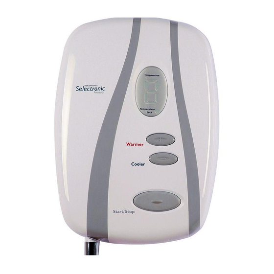
Temperature
Selectronic
Premier
Temperature
Lock
Warmer
Cooler
Start/Stop
IMPORTANT!
PLEASE REMOVE THE
IMPORTANT
"USER INFORMATION" LABEL
This booklet should be given to the customer
FROM FRONT COVER IF THIS
after installation and demonstration
IS A CARE INSTALLATION
Advertisement
Table of Contents

Related Manuals for Redring Selectronic Premier


Summary of Contents for Redring Selectronic Premier
- Page 1 Selectronic Premier Thermostatic Instantaneous Electronic Shower Handbook Temperature Selectronic Premier Temperature Lock Warmer Cooler Start/Stop IMPORTANT! PLEASE REMOVE THE IMPORTANT “USER INFORMATION” LABEL This booklet should be given to the customer FROM FRONT COVER IF THIS after installation and demonstration IS A CARE INSTALLATION...
-
Page 2: Product Dimensions
INSTRUCTION CONCERNING USE OF THE APPLIANCE IN A SAFE WAY AND UNDERSTAND THE HAZARDS INVOLVED. CHILDREN SHALL NOT PLAY WITH THE APPLIANCE. CLEANING AND USER MAINTENANCE SHALL NOT BE MADE BY CHILDREN Selectronic Premier Selectronic Premier Plus (with 1.25m Hose) (with 2m Hose) 264 mm... -
Page 3: Table Of Contents
Contents Installer Information;- Page Page User Information Product Dimensions Product Dimensions Installation Instructions How To Use Your Shower Plumbing Connections How Your Shower Works Electrical Connections Handset Operation Changing The Operation Mode Routine Maintenance Templock/Normal Periodical Maintenance Changing ‘DIP Switch’ Default Setting Trouble Shooting (User) Commissioning BEAB Care Wash Scheme... - Page 4 This has 1500x1500 Wheelchair Turning Space been made a firm fit to aid stability and stop rotation. All measurements shown are in millimetres. Drawing sizes are not to scale. Shower model shown is a Selectronic Premier Plus.
-
Page 5: Plumbing Connections
Plumbing Connections Diagram 2 Plumbing to be carried out before wiring DO NOT use jointing compounds on any pipe fittings for the installation. DO NOT solder fittings near the shower unit as heat can travel along pipework and damage components. Compression fittings MUST be used to connect to the inlet of the shower. - Page 6 Connect the mains water supply to the Inlet of the shower via 15mm copper, stainless steel or plastic pipe using a 15mm compression fitting. See (Diagram 4) for advice on Rear Entry fitting. The Inlet fitting is designed to rotate through 180° to allow for either Top or Bottom/Rear entry fitting (See Diagrams 3).
-
Page 7: Electrical Connections
If you are replacing an earlier model of the Redring Selectronic you will need to remove the appropriate backplate section subject to whether the mains water plumbing approach is either top or bottom entry. See Diagram 2 - Options ‘A’ or ‘B’. - Page 8 entry points then the following backplate component will need to be discarded allowing Diagram 5 for the conduit to fit into the backplate. See Diagram 5 - Option ‘E’ or ‘F’. CIRCUIT PROTECTION Unit Cartridge Rating Fuse 8.5kW 9.5kW 40/45A 10.8kW Twin and earth PVC insulated cable Current carrying capacity...
-
Page 9: Changing The Operation Mode
On the extreme right hand side of the PCB mid way up is the ‘4 Way Temp Limit Slider LOCKED POSITION Switch’ (See Diagram 8). ’2’ PLEASE NOTE! The Selectronic Premier is factory set with the ‘Temp Limit Slider Switch’ set at ‘Locked Position 1’. LOCKED POSITION ’3’... - Page 10 Previous Setting DIP 6: Maximum Flow Limiter Flow Limited to 6 l/m max Flow Limited to 9 l/m max PLEASE NOTE! The Selectronic Premier is Diagram 9 factory set with the ‘DIP Switch’ set as follows:- 4 at ‘0’ (Fixed Flow) 5 at ‘0’...
-
Page 11: Commissioning
Commissioning Diagram 10 Ensure the water and electricity are switched on to the unit. Press and hold the Cooler button until confirmed with one audible short bleep. Audible Short Audible Short See Diagram 10 Bleep Bleep The digital display will illuminate with a capital “C”. -
Page 12: How To Use Your Shower
How To Use Your Shower Temperature Lock Light Diagram 13 Temperature Selectronic Premier Temperature Audible Short Lock Bleep Warmer Cooler Warmer Start/Stop Cooler Start / Stop To Switch The Shower On : Switch On Electricity at ceiling / isolating switch. Press the Start / Stop button. - Page 13 Diagram 15 Press the Cooler Button to decrease the temperature. (See Diagram 15). Audible Short Bleep (Confirmed with a Single bleep). Always wait for a few seconds for the temperature to change to the new setting. Diagram 16 Pressing the Warmer Button when the temperature is at Maximum will not increase the temperature.
- Page 14 To Switch the Shower Off : Diagram 18 To switch the shower off, press the Start /Stop button. (Confirmed with 3 short bleeps). Audible Short (See Diagram 18). Bleeps IMPORTANT NOTE! Always use the Start/Stop button to switch the shower OFF.
- Page 15 It can take a long time for the unit to reach a safe temperature. To speed this temperature reduction up, the hot water can be purged from the unit. Purging While the unit is in “O” (Over) “t” (Temperature) shutdown mode. Press the Diagram 21 cooler button for more than 3 seconds.
-
Page 16: How Your Shower Works
Temperature Lock Override Note: For Care Wash installations the Temperature Lock Switch MUST be set to ON (Templock Position 1 or 2) and must Diagram 24 not be overridden. The temperature lock feature can be overridden, while the shower is running, by pressing the warmer and cooler buttons together for more than three seconds (See Diagram 24). - Page 17 5. A stabiliser is built into the flow SWITCH valve to automatically compensate TERMINAL for small fluctuations in water BLOCK WARNING THIS pressure that frequently occur in PRODUCT MUST BE EARTHED households. TEMPLOCK LOGIC There are three further controls to SWITCH cater for exceptional reductions in water pressure to prevent the...
-
Page 18: Handset Operation
Handset Operation There are five defined spray plate setting modes (patterns) adjustable by rotating the spray plate (see Diagram 25). These modes (patterns) have a positive click to identify them. The spray plate rotates through a limited travel and changes spray pattern with every click. So you can choose your favourite setting to enhance your shower experience. -
Page 19: Trouble Shooting (Installer)
Periodical Maintenance Diagram 26 Cleaning the Filter It is recommended that the filter is periodically cleaned in order to maintain the performance of the shower. It is essential that this operation is carried out by a competent person. WARNING! Switch OFF the electricity at the isolating switch and the water supply at the mains before removing the cover. -
Page 20: Beab Care Wash Scheme
Switch OFF electricity at ceiling/wall isolating switch, d) Display behaves erratically. wait a few seconds, switch on again. (Note: The shower should be switched OFF each time after use at the ceiling/wall isolating switch. e) Water does not flow when START/STOP Note: If there is no water flowing then the shower will automatically switch OFF after about 5 seconds. -
Page 21: Spares
Spares (Ring 0344 372 3587 UK ONLY) Please Note:- The fitting of all spares should be supervised by a suitably qualified person Description Part No, Part No. Description 93594147 Complete Remote Control Set 93594102 Triac PCB 93594150 Backplate Rubber Seal Set 93594104 Flow Valve Assy (No Outlet) Receiving PCB... - Page 22 Diagram 27 Use the wall brackets to mark rawl plug positions on wall. Clip reinforcing plates into position before fixing screws in place. Slide / push riser rail into position then push the bracket covers into place locating the clips at the open end into the slots. EASY CLEAN SOAPDISH HOSE RETAINER REINFORCING PLATES...
- Page 23 Diagram 28 SCREW COVER After fixing the brackets to the wall, slide the fixings covers over behind rail, push covers into place locating the clips at the open end into the slots If the shower hose supplied has protective plastic caps on the hose cones, please remove them and then: Connect the hose cone ends to...
-
Page 24: Guarantee
You must provide to Redring or its authorised agents on request the original receipt as proof of purchase and - if required by Redring - proof of delivery. If you are unable to provide this documentation, you will be required to pay for any repair work required.
Need help?
Do you have a question about the Selectronic Premier and is the answer not in the manual?
Questions and answers