Table of Contents
Advertisement
Quick Links
1500 - - - - E4500
1500
1500
1500
Combustion Analyzer
Combustion Analyzer
Combustion Analyzer
Combustion Analyzer
OPERATING & MAINTENANCE
OPERATING & MAINTENANCE
OPERATING & MAINTENANCE
OPERATING & MAINTENANCE
Respect your environment: think before printing the full manual on paper
E4500
E4500
E4500
MANUAL
MANUAL
MANUAL
MANUAL
Document covers both E and BTU
version analyzers (E4500/BTU4500)
Advertisement
Table of Contents

Related Manuals for E Instruments E4500


Summary of Contents for E Instruments E4500
- Page 1 1500 - - - - E4500 1500 E4500 1500 1500 E4500 E4500 Combustion Analyzer Combustion Analyzer Combustion Analyzer Combustion Analyzer Document covers both E and BTU version analyzers (E4500/BTU4500) OPERATING & MAINTENANCE OPERATING & MAINTENANCE OPERATING & MAINTENANCE OPERATING & MAINTENANCE...
-
Page 3: Table Of Contents
TABLE OF CONTENTS IMPORTANT INFORMATION Introduction Safety warnings SAFETY Intended use of the product Improper use of the product WORKING PRINCIPLE Working principle Measuring Sensors DESCRIPTION OF THE PRODUCT General Description of the Combustion Analyzer General Characteristics of the Combustion Analyzer Description of the Components of the Combustion Analyzer 4.3.1 Keypad... - Page 4 TABLE OF CONTENTS POWER ON - OFF Starting the device CONFIGURATION Configuration Menu Analysis Menu 9.2.1 Configuration=>Analysis=>Fuel 9.2.2 Configuration=>Analysis=>Condensation 9.2.3 Configuration=>Analysis=>O reference 9.2.4 Configuration=>Analysis=>NO /NO ratio 9.2.5 Configuration=>Analysis=>Measuring Units 9.2.6 Configuration=>Analysis=>Autozero 9.2.7 Configuration=>Analysis=>Measures list Instrument Menu 9.3.1 Configuration=>Instrument=>Bluetooth 9.3.2 Configuration=>Instrument=>Time/Date 9.3.4 Configuration=>Instrument=>Brightness 9.3.5...
- Page 5 TABLE OF CONTENTS 11.2 Print=>Report 11.3 Print=>Configuration 11.4 Print=>Test 11.5 Print=>Header 11.6 Print=>Printer 11.6.1 Print=>Printer=>Pairing 11.7 Print=>Measures list 12.0 MEASUREMENTS 12.1 Measurements Menu 12.2 Measurements=>Draft 12.3 Measurements=>Smoke 12.4 Measurements=>Ambient CO 12.5 Measurements=>Temperature 12.6 Measurements=>Pressure 12.7 Measurements=>Tightness test 12.7.1 Connection of the tool tightness test kit 12.8 Measurements=>Tightness test=>New System 12.8.1 Performing tightness test according to UNI 7129...
- Page 6 ANNEX B - Coefficients of the fuels and Formulas ANNEX C - Declaration of Conformity E INSTRUMENTS INTERNATIONAL LLC - ALL RIGHTS RESERVED - Total or partial reproduction of this document by any means (including photocopying or storage on any electronic medium) and transmittal of same to third parties in any manner, even electronically, is strictly prohibited unless explicitly authorised in writing by E INSTRUMENTS INTERNATIONAL LLC.
-
Page 7: Important Information
1.1 Information about this manual This manual describes the operation and the characteristics and the maintenance of the Combustion Analyzer model E4500. Read this operation and maintenance manual before using the device. The operator must be familiar with the manual and follow the instructions carefully. -
Page 8: Safety
2.2 Improper use of the product The use of E4500 in application areas other than those specified in Section 2.1 "Intended use of the product" is to be considered at the operator’s risk and the manufacturer assumes no responsibility for the loss damage or costs that may result. -
Page 9: Working Principle
WORKING PRINCIPLE 3.1 Working principle The gas sample is taken in through the gas probe, by a diaphragm suction pump inside the instrument. The measuring probe has a sliding cone that allows the probe to be inserted in any stack with the gas probe tip roughly centered in the flue. -
Page 10: Description Of The Product
Its internal memory is able to store 2000 complete tests and using the dedicated SW and mini-USB serial communication cable it is possible to download the data to a PC. It is also interesting to know that "E4500" is equipped with a single "Li-Ion" rechargeable battery pack used both to power the unit and for the printer: it also has a bright and wide (55 x 95 mm) TFT color display that has an excellent readability also thanks to the zoom function and the backlight. - Page 11 E Instruments does, however, certify measurement accuracy only when a calibration certificate has been issued by its own laboratory or by an authorized laboratory.
-
Page 12: Description Of The Components Of The Combustion Analyzer
4.3 Overview of Flue Gas Analyzer Components C C C C Q Q Q Q Q Q Q Q D D D D B B B B E E E E O O O O P P P P A A A A F F F F G G G G Q Q Q Q... -
Page 13: Keypad
4.3.1 Keypad Adhesive polyester keypad with keys for main control functions: KEYS FUNCTION KEYS FUNCTION Activates context Turns the device On / keys shown display Access to the Memory Exits the current screen menu Access to the Printing Select and/or Modify menu Confirm/Save settings A c c e s s... -
Page 14: Printer
4.3.3 Printer Thermal polyester or thermal paper. Thermal polyester cannot be altered and it is resistant to light, temperature, humidity and water. The print menu is accessed by pressing the relative key and, besides enabling read-out printing, the menu also allows you to modify print settings and to feed the paper manually for paper roll replacement. -
Page 15: Main Configurations
MAIN CONFIGURATIONS 1500 E4500-2 E4500-3 E 4500-N E 4500-S E4500-C O2 SENSOR CO+H2 SENSOR NO SENSOR NO2 SENSOR SO2 SENSOR CxHy SENSOR NOT EXPANDABLE POSSIBILITY OF UPGRADING TO 4 SENSOR AUTOMATIC AUTOZERO CO DILUTION BLUETOOTH TIGHTNESS TEST CALIBRATION CERTIFICATE QUICK GUIDE GAS SAMPLE PROBE 300mm (12”) + 10’... -
Page 16: Technical Specifications
TECHNICAL SPECIFICATIONS 6.1 Technical Specifications Autozero: Automatic autozero cycle. Dilution (where provided): Expansion system of the CO sensor measuring range up to 100,000ppm (10.00%) programmable as a simple protection of the CO sensor with triggering threshold programmable by the user. Preset triggering threshold at 1500 ppm. -
Page 17: Measurement And Accuracy Ranges
6.2 Measurement and Accuracy Ranges MEASUREMENT SENSOR RANGE RESOLUTION ACCURACY Electrochemical sensor 0 .. 25.0% vol 0.1% vol ±0.2% vol ±10 ppm 0 .. 200 ppm Electrochemical sensor 0 .. 8000 ppm 1 ppm ±5% measured value 201 .. 2000 ppm with H compensation ±10% measured value... -
Page 18: Startup
Remove the instrument from its packing and check it for damage. Make sure that the content corresponds to the items ordered. If signs of tampering or damage are noticed, notify the E INSTRUMENTS service center or distributor immediately and keep the original packing. A label on the back of the analyzer bears the serial number. -
Page 19: Use With External Power Pack
7.3.2 Use with external power pack The instrument can work with the batteries fully discharged by connecting the external power pack provided. THE POWER SUPPLY/BATTERY CHARGER IS A SWITCHING TYPE ONE. THE APPLICABLE INPUT VOLTAGE RANGES BETWEEN 90Vac AND 264Vac. INPUT FREQUENCY: 50-60Hz. -
Page 20: Connection Diagram
7.4 Connection diagram AA AL05 AAC TA03A AAC KP01 AA SA08 AAC SO01 AA SF--A K000000000EJ 023826A0 100714... -
Page 21: Gas Sampling Probe
7.4.1 Gas sampling probe The gas sampling probe is made up of an INOX steel tube with a plastic hand grip and an internal K-type thermocouple (Ni-NiCr) for measuring the gas temperature up to 1470°F (800°C). Flue gas temperature is measured by means of a thermocouple inserted in the tip of the probe. -
Page 22: Connecting The Tc-K Probe
7.4.5 Combustion air temperature probe (for Condensing Boilers/Furnaces) The probe to measure the temperature of the combustion air (necessary for an exact calculation of the efficiency of the appliance) features a stainless steel tube with an adapter for wells of the diameter of 7.5 / 17 mm and K- type internal thermocouple (Ni-NiCr) to measure the temperature between -4°F and 212°F (-20°C and +100°C.) The probe comes complete with an 80”... -
Page 23: Power On - Off
∆T ∆T 74.7 74.7 °C °C hold for a Loss tot Loss tot E4500-N Eff. tot Eff. tot 91.4 seconds 91.4 Serial number: 1000 Firmware version: 1.00 During autozero, you can only use the menus that do not require autozero. -
Page 24: Configuration
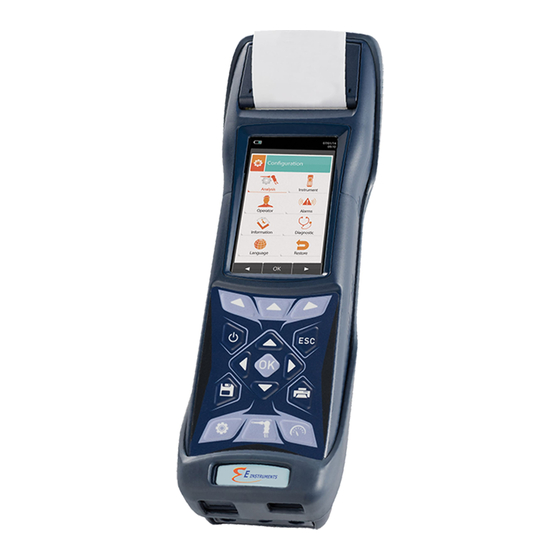
CONFIGURATION 9.1 Configuration menu 07/08/14 FUNCTION 10:00 Activate the context keys shown on the Configuration display. Returns to the previous screen. Analysis Instrument Operator Alarms CONTEXT KEY FUNCTION ◄ Selects the available parameters. Information Diagnostic Enters in the selected parameter setting. Language Restore ►... -
Page 25: Analysis Menu
Configuration→Analysis → 07/08/14 FUNCTION 10:00 Activate the context keys shown on the Configuration display. Analysis Returns to the previous screen. Fuel Condensation reference CONTEXT KEY FUNCTION /NO ratio ◄ Selects the available parameters. Measure units Autozero Enters in the selected parameter setting. Measures list ►... -
Page 26: Configuration=>Analysis=>Fuel
9.2.1 Configuration→Analysis→Fuel → 07/08/14 07/08/14 10:00 10:00 Configuration Configuration Fuel Fuel Natural gas Pellet 8% Propane Wood 20% L.P.G. Woodchips Butane Coal Diesel oil Fuel oil Propane-Air Biogas FUNCTION Activate the context keys shown on the display. The arrows select each line displayed. Confirms the choice of fuel to be used during the analysis. -
Page 27: Configuration=>Analysis=>Condensation
9.2.2 Configuration→Analysis→Condensation → 07/08/14 10:00 Configuration Condensation Altitude Altitude above sea level R.H. air Relative humidity of air FUNCTION Activate the context keys shown on the display. The arrows select each line displayed (the selected line is red). In edit mode, it scrolls through the suggested values. Enters the modify mode for the selected parameter, then confirms the modification. -
Page 28: Reference
9.2.3 Configuration→Analysis→Reference O → 07/08/14 10:00 Configuration reference Percentage of Oxygen in CO measurement Percentage of Oxygen in NO measurement Percentage of Oxygen in SO measurement FUNCTION Activate the context keys shown on the display. Keys '▲' and '▼' select any line shown on the display (the selected line is evidenced in red). -
Page 29: Ratio
9.2.4 Configuration→Analysis→NO /NO ratio → 07/08/14 10:00 Configuration /NO ratio 1.05 FUNCTION Activate the context keys shown on the display. When in modify mode, sets the desired value. Enters edit mode of the selected element and then confirms the change. When pressed in modify mode cancels the selection made, otherwise returns to the previous screen. - Page 30 9.2.5 Configuration→Analysis→Measurement units → 07/08/14 10:00 Configuration Measure units Measurement unit can be set as: ppm - mg/m - mg/kWh - g/GJ - g/m - g/kWh - % Measurement unit can be set as: ppm - mg/m - mg/kWh - g/GJ - g/m - g/kWh - % Measurement unit can be set as: ppm - mg/m - mg/kWh - g/GJ - g/m...
-
Page 31: Configuration=>Analysis=>Autozero
9.2.6 Configuration→Analysis→Autozero → 07/08/14 10:00 Configuration Autozero Autozero Duration of autozero, expressed in seconds. Purging Duration of the cleaning cycle, expressed in seconds. FUNCTION Activate the context keys shown on the display. When in modify mode, sets the desired value. Enters edit mode of the selected element and then confirms the change. -
Page 32: Configuration=>Analysis=>Measures List
9.2.7 Configuration→Analysis→Measures list → 07/08/14 10:00 Configuration Measures list Ex. Air T flue T air ∆T Loss tot (PCI) Eff. tot (PCI) » FUNCTION Activate the context keys shown on the display. Select each line displayed (the line selected is red). In edit mode, it sets the desired value. - Page 33 Example: → 1. Add a measurement to the list - example 07/08/14 07/08/14 07/08/14 07/08/14 10:00 10:00 10:00 10:00 Configuration Configuration Configuration Configuration Measures list Measures list Measures list Measures list Ex. Air Ex. Air ▲ T flue T flue Ex.
-
Page 34: Instrument Menu
Configuration→Instrument → 07/08/14 FUNCTION 10:00 Activate the context keys shown on the Configuration Instrument display. Returns to the previous screen. Bluetooth Time/Date Brightness Pump CONTEXT KEY FUNCTION ◄ Selects the available parameters. CO dilutor Micromanometer Enters in the selected parameter setting. ►... -
Page 35: Configuration=>Instrument=>Bluetooth
07/08/14 10:00 Bluetooth Bluetooth enabling / disabling Status Instrument name E4500 - 0001 MAC address detected 00026BB5500 FUNCTION Activate the context keys shown on the display. Also activates the context key shown on the display. Returns to the previous screen. -
Page 36: Configuration=>Instrument=>Time/Date
9.3.2 Configuration→Instrument→Time/Date → 07/08/14 10:00 Configuration Time/Date Time, in the chosen format Time 3:00 PM Date, in the chosen format Date 7/08/14 Date format: USA (American) or EU (European) Mode Time format: 12h or 24h Mode 12 h FUNCTION Activate the context keys shown on the display. When in modify mode, sets the desired value. -
Page 37: Configuration=>Instrument=>Brightness
9.3.3 Configuration→Instrument→Brightness → 07/08/14 10:00 Configuration Brightness FUNCTION Activate the context keys shown on the display. Increases or decreases the brightness of the display. Confirms the modification. When pressed in modify mode cancels the selection made, otherwise returns to the previous screen. CONTEXT KEY FUNCTION ◄... -
Page 38: Configuration=>Instrument=>Pump
9.3.4 Configuration→Instrument→Pump → 07/08/14 10:00 Configuration Pump Pump Flow Displays the flow of the pump, expressed in litres per minute. l/min FUNCTION Activate the context keys shown on the display. When in modify mode, sets the desired value. Enters edit mode of the selected element and then confirms the change. When pressed in modify mode cancels the selection made, otherwise returns to the previous screen. -
Page 39: Configuration=>Instrument=>Co Dilution
9.3.5 Configuration→Instrument→CO dilutor → 07/08/14 10:00 Configuration CO dilutor Available settings: auto, on or off Mode auto Limit Threshold that activates the dilution pump (available only if the "Mode" parameter is set o 1500 "auto". FUNCTION Activate the context keys shown on the display. Select each line displayed (the line selected is red). -
Page 40: Configuration=>Instrument=>Micromanometer
9.3.6 Configuration→Instrument→Micromanometer → 07/08/14 10:00 Configuration Micromanometer Sets the input used for the test: P+ o P- Inlet FUNCTION Activate the context keys shown on the display. In edit mode, it sets the desired input. Enters edit mode of the selected element and then confirms the change. When pressed in modify mode cancels the selection made, otherwise returns to the previous screen. -
Page 41: Configuration=>Operator
Configuration→Operator → 07/08/14 10:00 Configuration Operator Operator 1 Operator 2 Operator 3 Operator 4 Operator 5 Operator 6 Operator 7 Operator 8 FUNCTION Activate the context keys shown on the display. In "edit text": Moves the cursor on the box corresponding to the letter or number required to form the word. - Page 42 Example: → 1. Edit text 07/08/14 07/08/14 07/08/14 10:00 10:00 10:00 Configuration Edit text Edit text Operator Operator 1 Operator 2 Operator 3 Operator 1_ Operator _ Operator 4 Operator 5 Operator 6 Operator 7 Operator 8 07/08/14 07/08/14 07/08/14 10:00 10:00 10:00...
-
Page 43: Configuration=>Alarm
Configuration→Alarm → 07/08/14 10:00 Configuration Alarms Number of the alarm set Number Monitored parameter: O - CO - NO - NO - P diff - Plow - P ext - T1 - T2 Measure Type of alarm set: Maximum, Minimum, Off Mode maximum Threshold setting for the alarm: ±999999.999... -
Page 44: Information Menu
Sensors SEE SECTION 9.6.2. This submenu contains details regarding the E Instruments’ Service Center to be contacted in the event of instrument fault or ordinary maintenance. The instrument model, serial number and firmware version are also displayed, thus allowing for a quick product identification. -
Page 45: Configuration=>Information=>Battery
9.6.1 Configuration→Information→Battery → 07/08/14 10:00 Information Battery 94 % FUNCTION Activate the context keys shown on the display. Returns to the previous screen. CONTEXT KEY FUNCTION Returns to the previous screen. K000000000EJ 023826A0 100714... -
Page 46: Configuration=>Information=>Sensors
9.6.2 Configuration→Information→Sensor → 07/08/14 07/08/14 10:00 10:00 Information Diagnostic Sensors Sensors S1: O S2: CO S3: NO For further information, see section 9.7.1. S4: NO FUNCTION Activate the context keys shown on the display. Returns to the previous screen. CONTEXT KEY FUNCTION Displays the details of the main features of the sensors installed. -
Page 47: Configuration=>Information=>Info Service
9.6.3 Configuration→Information→InfoService → 07/08/14 10:00 FUNCTION Information Service Activate the context keys shown on the display. E Instruments 402 Middletown Blvd, Ste. 216 Returns to the previous screen. Langhorne, PA 19047 USA Tel. 215-750-1212 Fax. 215-750-1399 CONTEXT KEY FUNCTION www.E-Inst.com info@E-Inst.com... -
Page 48: Configuration=>Diagnostic
Configuration→Diagnostic → 07/08/14 FUNCTION 10:00 Activate the context keys shown on the Diagnostic display. Returns to the previous screen. Sensors Gas probe Hardware Pump CONTEXT KEY FUNCTION ◄ Selects the available parameters. On site cal. Enters in the selected parameter setting. ►... -
Page 49: Configuration=>Diagnostic=>Sensors
9.7.1 Configuration→Diagnostic→Sensors → 07/08/14 10:00 Diagnostic Sensors S1: O S2: CO S3: NO S4: NO FUNCTION Activate the context keys shown on the display. Selects the fuel. Activates the context keys located in the left side of the display. Returns to the previous screen. CONTEXT KEY FUNCTION Displays the details of the selecter sensor (see example below). -
Page 50: Configuration=>Diagnostic=>Gas Probe
9.7.2 Configuration→Diagnostic→Gas probe → 07/08/14 10:00 Diagnostic Connect the flue gas sampling probe and water trap assembly to the Gas probe instrument; Close the flue gas probe Fully insert the black rubber cap on the gas probe tip, as shown in the following picture: Press OK to start Black rubber cap... -
Page 51: Configuration=>Diagnostic=>Memory
9.7.3 Configuratione→Diagnostic→Hardware → 07/08/14 10:00 Diagnostic Hardware State of memory. Memories State of calibration. Calibration Version of CPU board HW Cpu version Version of motherboard HW MB version FUNCTION Activate the context keys shown on the display. Returns to the previous screen. CONTEXT KEY FUNCTION Returns to the previous screen. -
Page 52: Configuration=>Diagnostic=>Pump
9.7.4 Configuration→Diagnostic→Pump → 07/08/14 10:00 Diagnostic Pump Pump Flow l/min FUNCTION Activate the context keys shown on the display. In edit mode, cycling between on and off. Enters edit mode of the selected element and then confirms the change. Returns to the previous screen. CONTEXT KEY FUNCTION Enters edit mode: it is possible to turn the gas suction pump on and off. -
Page 53: Configuration=>Diagnostic=>On Site Calibration
9.7.5 Configuration→Diagnostic→On site cal. → 07/08/14 10:00 Password On site calibration 0 0 0 0 FUNCTION Activate the context keys shown on the display. Sets the password. Selects line; the selected line is evidenced in red. In modification sets the value or the desired mode. Activates the context key located in the left side of the display. - Page 54 ∆T ∆T 74.7 74.7 °C °C pressed for Loss tot Loss tot a few E4500-N Eff. tot Eff. tot seconds 91.4 91.4 Serial number: 1000 Firmware version: 1.00 ATTENTION Make sure autozero is performed in clean air and completes properly.
- Page 55 → 3. Once in the ‘On site calibration’ menu, the list of the installed sensors are shown for which the recalibration is available. In the recalibration screen all information related to the last performed calibration is shown, as well as the relevant values. Calibrate: saves new calibration 07/08/14...
- Page 56 → 07/08/14 07/08/14 07/08/14 10:00 10:00 10:00 On site calibration On site calibration On site calibration Sensor CO Sensor CO Sensor CO Calibrate Calibrate Calibrate Status active Status active Status not active Elapsed time 00:00:00 Elapsed time 00:00:00 Elapsed time 00:00:00 Applied gas Applied gas...
- Page 57 → 07/08/14 07/08/14 10:00 10:00 Messages in the 'Status' line: On site calibration On site calibration saving: instrument saving Sensor CO Sensor CO performed calibration Calibrate Calibrate error: sensor been Status not active Status active recalibrated for any of the following Elapsed time 00:03:00 Elapsed time...
-
Page 58: Configuration=>Language
Configuration→Language 07/08/14 10:00 Configuration Language Italiano English Français Espaňol Deutsch Poccийcкo FUNCTION Activate the context keys shown on the display. Scrolls through the available languages. Sets the selected language. Returns to the previous screen. CONTEXT KEY FUNCTION Sets the selected language. K000000000EJ 023826A0 100714... -
Page 59: Configuration=>Restore
Configuration→Restore 07/08/14 07/08/14 10:00 10:00 Configuration Configuration Restore Restore WARNING Clear memory data and Confirm restoring? restore factory setting? F1: restore F2: cancel di fabbrica? FUNCTION Activate the context keys shown on the display. Starts the factory data reset phase. Exits the current screen without resetting. -
Page 60: Memory
10.0 MEMORY 10.1 Memory Menu 07/08/14 FUNCTION 10:00 Activate the context keys shown on the Memory display. Returns to the previous screen. Save Average Select Data logger CONTEXT KEY FUNCTION ◄ Selects the available parameters. Delete Usage % Enters in the selected parameter setting. ►... - Page 61 Warning: in automatic mode, the measurements of draft, smoke and ambient CO must be taken before starting the combustion analysis. Manual analysis mode If the user chooses the manual mode, he will perform the combustion analysis manually; in this case, the settings regarding printing and duration of the automatic analysis will not be considered.
-
Page 62: Memory=>Save
10.2 Memory Menu→Save 07/08/14 07/08/14 10:00 10:00 Memory Memory Save Save Manual analysis mode Automatic analysis mode Mode manual Mode UNI 10389 Number of selected memory Number of selected memory Memory Memory Number of analyses carried Number of samples to take Analysis Samples Interval... - Page 63 Example 1: Saving the combustion analysis in manual mode 07/08/14 07/08/14 07/08/14 10:00 10:00 10:00 Memory Memory Memory Save Save Save Mode manual Mode manual Mode manual Memory Memory Memory Analysis Analysis Analysis Example 2: Saving the combustion analysis in automatic mode (example UNI 10389) 07/08/14 07/08/14 07/08/14...
-
Page 64: Memory=>Average
10.3 Memory Menu→Average 07/08/14 10:00 Memory Average analysis Ex. Air 1.25 T flue 190.1 °C T air 15.4 °C ∆T 74.7 °C Loss tot Eff. tot 91.4 FUNCTION Activate the context keys shown on the display. Scrolls through the values of the average analysis. Activates the context key located in the left side of the display. -
Page 65: Memory Select
Memory Select Select Memory number Boiler model Memory Boiler xxxx Customer Address of the cus- Customer Address E Instruments tomer Address of the cus- Address 402 Middletown tomer Ste 216 Telephone number Langhorne, PA 19047 Phone Telephone number Phone 215-750-1212... -
Page 66: Memory=>Memory Recall
10.4.1 Memory Recall 07/08/14 07/08/14 10:00 10:00 Memory Memory Select Recall Memory Measure conditions Customer Single analysis E Instruments Address 402 Middletown Average analysis Ste 216 Langhorme, PA 19047 Phone 215-750-1212 Boiler xxxx Date 7/08/14 FUNCTION Activate the context keys shown on the display. - Page 67 2. Details of Single analysis 07/08/14 07/08/14 10:00 10:00 Memory Memory Single analysis Average analysis 07/08/14 15:10:30 07/08/14 15:15:00 Ex. Air 07/08/14 15:20:30 1.25 T flue 07/08/14 15:25:00 190.1 °C T air 07/08/14 15:30:35 15.4 °C ∆T 74.7 °C Loss tot Eff.
- Page 68 3. Average interval details 07/08/14 07/08/14 10:00 10:00 Memory Memory Defines the starting sample to define the analysis Average Average analysis average. Defines the end sample to define the analysis average. Ex. Air 1.25 T flue 190.1 °C T air 15.4 °C ∆T...
-
Page 69: Memory Data Logger
10.5 Memory Menu→Data logger 07/08/14 10:00 Memory Data logger Mode The selectable analysis modes are: manual - UNI 10389 - BImSchV - data logger UNI 10389 Samples Number of samples to make (parameter not visible in manual analysis mode). Interval Period of acquisition of each sample (parameter not visible in manual analysis mode). -
Page 70: Memory=>Delete
10.6 Memory→Delete 07/08/14 FUNCTION 10:00 Activate the context keys shown on the Memory display. Delete Returns to the previous screen. Single CONTEXT KEY FUNCTION ◄ Selects the available parameters. Enters in the selected parameter setting. ► Selects the available parameters. PARAMETER DESCRIPTION This option allows the user to delete the contents of each individual memory;... -
Page 71: Memory=>Delete=>Single
07/08/14 10:00 10:00 Memory Memory Delete single Delete single Memory number Memory Memory Customer Customer Customer E Instruments E Instruments WARNING Address of the cus- Address 402 Middletown Address 402 Middletown Confirm deleting? tomer Ste 216 Ste 216 F1: Delete... -
Page 72: Memory=>Delete=>All
10.6.2 Memory→Delete→All 07/08/14 07/08/14 10:00 10:00 Memory Memory Delete all Delete all WARNING Confirm deleting? Delete all data? F1: Delete F2: cancel FUNCTION Activate the context keys shown on the display. Start erasing all memories. Returns to the previous screen. CONTEXT KEY FUNCTION Start erasing all memories. -
Page 73: Memory=>Usage
10.7 Memory→Usage % 07/08/14 10:00 Memory Usage % FUNCTION Activate the context keys shown on the display. Returns to the previous screen. CONTEXT KEY FUNCTION Returns to the previous screen. K000000000EJ 023826A0 100714... -
Page 74: Print
11.0 PRINT 11.1 Print 07/08/14 FUNCTION 10:00 Activate the context keys shown on the Print display. Returns to the previous screen. Report Configuration Test Header CONTEXT KEY FUNCTION ◄ Selects the available parameters. Printer Measures list Enters in the selected parameter setting. ►... -
Page 75: Print=>Report
11.2 Print→Report 07/08/14 07/08/14 Date: 07/08/14 10:00 10:00 Time: 10.10 Fuel: Natural gas Altitude: 0 m Print Print R.H. air: 50 % Report Report 4.2 ٪ 9.3 ٪ Analysis running Analysis running Ex. Air 1.25 T flue 190.2 °C Model partial Model partial... -
Page 76: Print=>Configuration
11.3 Print→Configuration 07/08/14 10:00 Print Configuration Set the number of copies to print: 1 .. 5. Copies The test ticket models that can be selected are: partial - full - total Model partial FUNCTION Activate the context keys shown on the display. Selects line;... -
Page 77: Print=>Test
11.4 Print→Test 07/08/14 10:00 Print Test Print Paper feed FUNCTION Activate the context keys shown on the display. Selects line; the selected line is evidenced in red. In modification sets the value or the desired mode. Activates the context key located in the left side of the display. Returns to the previous screen. -
Page 78: Print=>Header
11.5 Print→Header 07/08/14 10:00 Print Header Line 1 ---- Line 2 ---- Line 3 ---- Line 4 ---- Line 5 ---- Line 6 ---- FUNCTION Activate the context keys shown on the display. In "edit text": It moves the cursor on the box corresponding to the letter or number required to form the desired word. - Page 79 Example: 1. Edit text 07/08/14 07/08/14 07/08/14 10:00 10:00 10:00 Print Edit text Edit text Header Line 1 ---- Line 2 ---- Line 3 ---- Operator 1_ Operator 1_ Line 4 ---- Line 5 ---- Line 6 ---- 07/08/14 07/08/14 07/08/14 10:00 10:00...
-
Page 80: Print=>Printer
11.6 Print→Printer 07/08/14 07/08/14 10:00 10:00 Print Print Printer Printer Printer type: built in (internal) - Bluetooth (external). Type built in Type Bluetooth Name of the Bluetooth printer associated with the ---- instrument. ---- Address of the Bluetooth printer associated with the instrument. -
Page 81: Print=>Printer=>Pairing
11.6.1 Print→Pairing 07/08/14 10:00 Print Report Configuration Pairing Header Printer Measures list FUNCTION Activate the context keys shown on the display. Selects line; the selected line is evidenced in red. In modification sets the value or the desired mode. Activates the context key located in the left side of the display. Returns to the previous screen. - Page 82 1. Once the Bluetooth printer is configured, proceed as follows: 07/08/14 07/08/14 07/08/14 10:00 10:00 10:00 Print Print Print Printer Printer SPP-R200 Select icon 'Pairing' to start configuration MPT-II Report Configuration WARNING Turn on the printer and start searching Pairing Header F1: search F2: esc...
-
Page 83: Print=>Measures List
11.7 Print→Measures list 07/08/14 10:00 Configuration Measures list Ex Air T flue T air ∆T Loss tot Eff. tot (PCI) » FUNCTION Activate the context keys shown on the display. Selects the available measurements from the suggested list. In edit mode, it scrolls through the measurements present. - Page 84 Example: 1. Add a measurement to the list 07/08/14 07/08/14 07/08/14 07/08/14 10:00 10:00 10:00 10:00 Configuration Configuration Configuration Configuration Measures list Measures list Measures list Measures list ▼ Ex. Air Ex. Air T flue T flue Ex. Air Ex. Air ▲...
-
Page 85: Measurements
12.0 READINGS 12.1 READINGS 07/08/14 FUNCTION 10:00 Activate the context keys shown on the Measurements display. Returns to the previous screen. Draft Smoke Ambient CO Temperature CONTEXT KEY FUNCTION ◄ Selects the available parameters. Pressure Tightness test Enters in the selected parameter setting. External probe ►... - Page 86 Pressure SEE SECTION 12.6. The E4500 can perform the tightness test on heating plants which use combustible gases according to the standards UNI 7129 and UNI 11137: 2012, respectively applicable to new or renewed pipings and to existing pipings. The result of this tightness test, whose steps are...
-
Page 87: Measurements Draft
12.2 Readings→Draft 07/08/14 07/08/14 07/08/14 10:00 10:00 10:00 Measurements Measurements Measurements Draft Draft Draft P diff P+ low P+ ext 0.001 0.001 0.001 inH2O inH2O inH2O To measure the draft proceed as follows: - Connect the probe pressure input hose to the instrument P+ input. - Enter the external air temperature. -
Page 88: Measurements Smoke
12.3 Readings→Smoke Test 07/08/14 10:00 Measurements Smoke Measure 1 Measure 2 Measure 3 Average - Measure the carbon black using the specific optional kit. - Enter the values found. - The values of the carbon black that you want to save must be acquired before saving the analyses. - To join the values of the smoke test to the measurements of the current analysis use the ' ' function. -
Page 89: Measurements Ambient Co
12.4 Readings→Ambient CO 07/08/14 10:00 Measurements Ambient CO CO max It is recommended to perform the autozero in the fresh, clean air, so that the ambient CO measurement is correct. It is advisable to turn on the instrument and wait for the autozero completion outside the area where the test is being performed. -
Page 90: Measurements Temperature
12.5 Readings→Temperature 07/08/14 07/08/14 10:00 10:00 Measurements Measurements Temperature Temperature T1 flow T1 flow 70.5 °C T2 return ∆T 45.2 °C °C ∆T 25.3 °C ∆T FUNCTION Activate the context keys shown on the display. Returns to the previous screen. CONTEXT KEY FUNCTION Accesses the acquisition of the temperature difference between the supply... -
Page 91: Measurements Pressure
12.6 Readings→Pressure 07/08/14 07/08/14 10:00 10:00 Measurements Measurements Pressure Pressure Measurement Measurement differential pressure by pressure by means of P diff P ext means of the internal external draft 0.01 0.01 pressure sensor. gauge. inH2O inH2O FUNCTION Activate the context keys shown on the display. Returns to the previous screen. -
Page 92: Measurements=>Tightness Test
12.7 Readings→Tightness test 07/08/14 FUNCTION 10:00 Activate the context keys shown on the Tightness test display. Returns to the previous screen. Existing Result CONTEXT KEY FUNCTION ◄ Selects the available parameters. Enters in the selected parameter setting. ► Selects the available parameters. PARAMETER DESCRIPTION With this menu it is possible to perform a tightness test, in accordance with UNI 7129, on new... -
Page 93: Measurements=>Tightness Test=>New System
12.8 NEW PIPING: UNI 7129 STANDARD 07/08/14 10:00 New piping Configuration Stabilization Duration of the stabilization phase that can be set between 15 and 240 minutes Printing mode, that can be set as manual or automatic. Print manual FUNCTION Activate the context keys shown on the display. Selects line;... - Page 94 10 Pa. The E4500 allows the user to customize the stabilization phase through the following parameter: WAIT TIME: it is the stabilization time and can be set by the user from 15 to 99 minutes. Please note that the UNI 7129 standard requires that the stabilization takes no less than 15 minutes, However, the wait can be interrupted by activating the context key '' although the range is not finished.
-
Page 95: Performing Tightness Test According To Uni 7129
12.8.1 PERFORMING TIGHTNESS TEST ACCORDING TO UNI 7129 07/08/14 07/08/14 07/08/14 10:00 10:00 10:00 New piping New piping New piping Configuration Configuration Configuration Stabilization Stabilization Stabilization Print Print Print manual manual manual 07/08/14 07/08/14 07/08/14 10:00 10:00 10:00 New piping New piping New piping Configuration... - Page 96 07/08/14 10:00 New piping Stabilization P diff Pressure of the system. 100.00 ∆P 1 min Pressure variation in the last minute. 100.00 Wait time 00:15:00 Waiting time to end the stabilization phase. o o o o The stabilization phase can be interrupted in any moment. Automatically 07/08/14 07/08/14...
- Page 97 Oper.: John Smith Print Sign.: ______________ Report Test according to UNI 7129 standard Analysis Running Indirect method Model Tightness test E4500 WARNING Serial: 999989 Printing. Date: 07/08/14 Please wait…. Time: 10.30 F1: stop Stab.duration: 00:15:00 Test duration: 00:01:00 Gas Fuel: Natural gas...
-
Page 98: Measurements=>Tightness Test=>Existing System
12.9 EXISTING PIPING: UNI 11137 STANDARD 07/08/14 10:00 Existing piping Configuration Stabilization Duration of the stabilization phase that can be set between 1 and 240 minutes. Printing mode, that can be set as manual or automatic. Print auto Fuel used in the system: L.P.G. - Natural gas. Fuel L.P.G. - Page 99 If you use volume calculation, for each section of piping it is necessary to set the material, the nominal diameter and the length of the same. The E4500 calculates the volume of the section ("partial volume") and it adds it up, activating the context key ' ' (sum piping), to the calculation of the volume of the system.
- Page 100 Press the key relative to the context key ' • Open the valve on the side where the syringe is connected, take exactly 100 ml (100 cc) of the gas present in • the system. Wait for the stabilization of the pressure of the system. After a few seconds, the device displays the measured •...
- Page 101 ∆P: Pressure variation between the last instant and the first instant of the test. If the pressure decreased, it presents a negative value. Qtest: Is the calculated leakage measured in dm /h according to the conditions under which the test has been performed, i.e.
-
Page 102: Configuration Of Tightness Test According To Uni 11137
12.9.1 CONFIGURATION OF TIGHTNESS TEST ACCORDING TO UNI 11137 07/08/14 07/08/14 07/08/14 10:00 10:00 10:00 Existing piping Existing piping Existing piping Configuration Configuration Configuration Stabilization Stabilization Stabilization Print manual Print manual Print manual Fuel Fuel Fuel L.P.G. L.P.G. L.P.G. Test gas Test gas Test gas Type test... - Page 103 07/08/14 07/08/14 07/08/14 10:00 10:00 10:00 Existing piping Existing piping Existing piping Configuration Configuration Configuration Stabilization Stabilization Stabilization Print manual Print manual Print manual Fuel Fuel Fuel L.P.G. L.P.G. L.P.G. Test gas Test gas Test gas Fuel Type test preliminary Type test preliminary Type test...
- Page 104 Alternatively Take, with the syringe (that comes with the tightness test kit), 100 ml of gas. If the volume measuring procedure of the system ends correctly, the E4500 automatically displays the measured volume, otherwise it requires another test. 07/08/14 07/08/14...
- Page 105 07/08/14 07/08/14 10:00 10:00 Existing piping Existing piping Configuration Calculate volume Stabilization Volume Total volume acquired. 18.0 Print auto Fuel L.P.G. Partial Volume of the section of piping set below. Test gas Sets the material of the section of piping. Type test complete Material...
-
Page 106: Performing Tightness Test According To Uni 11137
12.9.2 PERFORMING THE TIGHTNESS TEST ACCORDING TO UNI 11137 Wait for 07/08/14 07/08/14 07/08/14 10:00 10:00 10:00 the end of the autozero Existing piping Existing piping Existing piping Pressurization Pressurization Pressurization pressurize the P diff P diff P diff system WARNING 0.06 Fill the system to... - Page 107 Oper.: John Smith Print Sign.: ______________ Scontrino Test according to UNI 7129 standard Analysis Running Indirect method Model Tightness test E4500 WARNING Serial: 999989 Printing. Date: 07/08/14 Please wait... Time: 10.30 F1: stop Stab. duration:00:15:00 Test duration: 00:01:00 Gas comb.: Natural gas...
-
Page 108: Measurements=>Tightness Test=>Results Of The Tightness Test
Oper.: John Smith Sign.: ______________ Print Report Test according to UNI 7129 standard Analysis Running Indirect method Model Tightness test E4500 WARNING Serial: 999989 Printing. Date: 07/08/14 Please wait... Time: 10.30 F1: stop Stab. duration:00:15:00 Test duration :00:01:00 Comb. gas: Natural gas... - Page 109 12.11 Measurements→External probe Not available. K000000000EJ 023826A0 100714...
-
Page 110: Combustion Analysis
13.0 FLUE GAS ANALYSIS 13.1 FLUE GAS ANALYSIS To perform complete flue gas analysis, follow the instructions below. SOME IMPORTANT WARNINGS TO CONSIDER DURING THE COMBUSTION ANALYSIS ARE LISTED BELOW: FOR A CORRECT ANALYSIS NO AIR MUST FLOW INTO THE PIPE FROM OUTSIDE DUE TO A BAD TIGHTENING OF THE POSITIONING CONE OR A LEAK IN THE PIPELINE. -
Page 111: Combustion Analysis
When auto-calibration is complete the instrument will instruct the user to insert the sample probe that has been previously connected to the relative input on the instrument, and the analysis screen will appear automatically. In order for the probe to be inserted at the right point within the stack, its distance from the boiler has to be twice the diameter of the stack pipe itself or, if this is not possible, must comply with the boiler manufacturer’s instructions. -
Page 112: Combustion Analysis - Preliminary Operations
13.2 FLUE GAS ANALYSIS - PRELIMINARY OPERATIONS 07/08/14 10:00 Combustion analysis Insert the gas sample probe in the chimney: Models (with automatic Ex. Air 1.25 autozero solenoid) E4500 T flue 190.1 °C T air 15.4 °C Do not insert the gas sample ∆T Hold down 74.7 °C... - Page 113 07/08/14 10:00 Print PARAMETERS BEFORE Report Configuration PROCEEDING (SEE SECTION 11.0): Configuration Test Header Header Measures list Printer Measures list 07/08/14 10:00 A C Q U I R E T H E F O L L O W I N G M E A S U R E M E N T S B E F O R E Measurements...
-
Page 114: Combustion Analysis - Manual Mode
13.3 PERFORMING COMBUSTION ANALYSIS - MANUAL MODE 07/08/14 07/08/14 07/08/14 10:00 10:00 10:00 Memory Combustion analysis Combustion analysis Save Mode manual Memory Ex. Air Ex. Air Analysis 1.25 1.25 T flue T flue 190.1 190.1 °C °C T air T air Saves 15.4 15.4... - Page 115 07/08/14 07/08/14 07/08/14 10:00 10:00 10:00 Memory Print Print Average analysis Report Report Memory Memory Analysis Average Analysis Average WARNING Ex. Air 1.25 Model partial Model Printing. partial Please wait... T flue 190.1 F1: stop °C T air 15.4 °C ∆T 74.7 °C...
-
Page 116: Combustion Analysis - Uni 10389 Mode
13.4 PERFORMING THE COMBUSTION ANALYSIS- UNI 10389 MODE 07/08/14 07/08/14 07/08/14 10:00 10:00 10:00 Combustion analysis Memory Combustion analysis Save UNI 10389 Mode UNI 10389 Memory Ex. Air Ex. Air Samples 1.25 1.25 Interval T flue T flue 190.1 190.1 °C °C Automatically saves... -
Page 117: Combustion Analysis - Bimschv Mode
13.5 PERFORMING THE COMBUSTION ANALYSIS - BImSchV MODE 07/08/14 07/08/14 07/08/14 10:00 10:00 10:00 Combustion analysis Memory Combustion analysis Save BImSchV Mode BImSchV Memory Ex. Air Ex. Air Samples 1.25 1.25 Interval T flue T flue 190.1 190.1 °C °C Automatically saves T air T air... -
Page 118: Combustion Analysis - Data Logger Mode
13.6 PERFORMING THE COMBUSTION ANALYSIS - data logger MODE 07/08/14 07/08/14 07/08/14 10:00 10:00 10:00 Combustion analysis Memory Combustion analysis Save data logger Mode data logger Memory Ex. Air Ex. Air Samples 1.25 1.25 Interval T flue T flue 190.1 190.1 °C °C... -
Page 119: Sensors
14.0 SENSORS 14.1 Sensors arrangement SENSOR ARRANGEMENT INSIDE GRAPHICAL DISPLAY OF ARRANGEMENT THE SENSOR COMPARTMENT 07/08/14 10:00 Information POSITION Sensors POSITION POSITION POSITION 14.2 Sensor types and relevant positioning POSITION CODE Flex-Sensor O Cod. AACSE11 Flex-Sensor O Cod. AACSE15 Flex-Sensor CO+H Cod. -
Page 120: Gas Sensors Life
Sensor characteristics diminish as the reagents are consumed and when these have been used up completely the sensor must be replaced. The sensors must be recalibrated on a regular basis to assure measuring accuracy: recalibration can only be performed by a qualified E INSTRUMENTS service center. Chart 14.4 illustrates the characteristics inherent to each sensor. -
Page 121: Expandability To 4 Sensors
14.5 Expandability to 4 sensors In the E4500 instruments range, two are the versions which can be expanded: E4500-2 E4500-3 2 sensors, expandable to 3 or 4 sensors. 3 sensors, expandable to 4 sensors. POSITION POSITION POSITION POSITION POSITION POSITION... -
Page 122: Cxhy Sensor For Measurement Of The Unburned Hydrocarbons
14.6 CxHy sensor for measurement of the Unburned hydrocarbons The Unburned hydrocarbons are chemicals produced by an incomplete combustion of molecules (hydrocarbons) made of Carbon and Hydrogen. These are usually named as HC or (better) CxHy: when this is filled with the actual values for the number of C and H atoms, the actual type of fuel is exactly defined. -
Page 123: Co Sensor For Carbon Dioxide Measurement In Combustion Processes
When the CO (position S3/S4) is mounted in the E4500, it is mandatory to configure the autozero by setting it at 60 seconds, in order to allow for a proper pre-heating of the sensor itself. Configuration→Analysis→Autozero (SEE SECTION 9.2.6) →... -
Page 124: Maintenance
Do not exceed sensor overload thresholds. • When the analysis is over disconnect the sample probe and let the E4500 draw fresh air for a few minutes, or • at least until the displayed parameters return to their original values. Do NOT bypass Post purge of the unit. -
Page 125: Maintaining The Water Trap / Filter Unit
15.4 Maintaining the water trap / filter unit To remove the water trap, just rotate the cover and unhook the filter holder body; remove the internal cup and then replace the filter (see figure on the side). Clean all the filter parts using water only, dry the components and reassemble the filter. 15.5 Replacing the particulate filter If the particulate filter appears black, especially on the inner surface (see adjacent example), it has to be replaced immediately. - Page 126 Locate the sensor to be replaced; here is an example of a connected sensor to be replaced. Electrical connection Disconnect the sensor to be replaced; here is an example of a disconnected sensor to be replaced. K000000000EJ 023826A0 100714...
- Page 127 The sensor is bayonet-connected to its socket; rotate it counter-clockwise to remove it. Here is an example of a rotated sensor. While rotating the sensor, take care not to exert any pressure onto the printed circuit above: exert pressure only onto the plastic body. After rotating the sensor, pull it upward;...
- Page 128 Rotate the sensor clockwise until hearing a click (See point 4). While rotating the sensor, take care not to exert any pressure onto the printed circuit above: exert pressure onto the plastic body only. Reconnect the sensor (See point 3). Close the back door of the sensor compartment again, and tighten screws again (See point 1).
-
Page 129: Replacing The Battery Pack
15.7 Replacing the battery pack Follow these instructions to replace the battery pack: Remove the battery compartment cover. Extract the battery pack. Remove the battery pack connector, and replace the pack with a new one following the reverse procedure described above. Battery pack connector K000000000EJ 023826A0 100714... -
Page 130: Replacing The Printer Paper Roll
15.8 Replacing the printer paper Follow these instructions to change the paper roll in the printer. Lift the top tile, indicated by the arrow. Lift the whole block of the lid completely. Insert the roll of printing paper as shown in the following figures. Close the whole block of the lid of the printer, At this point it is possible to use the printer. -
Page 131: Troubleshooting
16.0 TROUBLESHOOTING 16.1 Troubleshooting guide SYMPTOM PROBABLE CAUSES AND REMEDIES a. Keep the On/Off key depressed for at least 2 The instrument does not work at all. When the On/Off pushbutton is pressed the instrument does not come seconds. b. The battery is low; connect the battery charger to the instrument. - Page 132 Troubleshooting guide SYMPTOM PROBABLE CAUSES AND REMEDIES The rear lighting of the display is not on. The backlighting LED’s are faulty. Contact the nearest service center to replace the display. a. Battery capacity is limited by low temperatures. To The batteries last less than 9 hours. achieve a longer battery life it is recommended to store the instrument at higher temperatures.
-
Page 133: Spare Parts And Technical Assistance
AAC TA03A: Particulate/water filter assembly with steel pipe and connector AA UA03: Adapter cable USB-A / mini USB-B 17.3 Service Center E Instruments International LLC 402 Middletown Blvd, Suite 216 Langhorne, PA 19047 (USA) Tel.: (215) 750-1212 Fax.: (215) 750-1399 E-mail: info@E-Inst.com... -
Page 134: Annex A - Analysis Report Examples
15.4 °C ∆T 174.8 °C Test according to Loss tot 8.6 ٪ UNI 10389-1 Eff. tot 91.4 ٪ ηc 4.9 ٪ E4500-3 ηt 91.4 ٪ Serial: 999989 148 ppm Memory: 01 40 ppm Analysis: Average /NO: 1.03 Date: 04/04/14 41 ppm Time: 10.30... - Page 135 Test according to 9.3 ٪ UNI 10389-1 Ex. Air 1.25 T flue 190.2 °C T air 15.4 °C ∆T 174.8 °C E4500-3 Loss tot 8.7 ٪ Serial: 999989 Eff. tot 91.4 ٪ Memory: 01 4.9 ٪ Analysis: Average ηt 91.4 ٪...
- Page 136 Tel.800-555-1234 Park Road, 9 Tel.800-555-1234 Oper.: John Smith Oper.: John Smith Sign.: ______________ Sign.: ______________ Test according to UNI 11137: 2012 standard E4500-3 Indirect method Serial: 999989 Memory: 01 E4500-3 Serial: 999989 Date: 04/04/14 Memory: 01 Time: 10.30 Date: 04/04/14...
-
Page 137: Annex B - Coefficients Of The Fuels And Formulas
ANNEX B Coefficients of the fuels and Formulas The following chart, derived from standard UNI 10389-1, lists the coefficients of the memorized fuels, used for calculating losses and efficiencies. Coefficients for calculating combustion efficiency Fuel CO2t M aria V gas dry (KJ/Kg) (KJ/Kg) (Kg/Kg) -
Page 139: Annex C - Declaration Of Conformity
ANNEX C DECLARATION OF CONFORMITY The manufacturer: E Instruments International LLC with registered address in: E Instruments International LLC 402 Middletown Blvd, Suite 216 Langhorne, PA 19047 USA declares that the following products: 1500 E4500-2 E4500-3 E4500-N E4500-S E4500-C is in conformity with the essential requirements of directives 2004/108/CE and 2006/95/CE. - Page 141 NOTE...
- Page 142 NOTE...
- Page 144 E INSTRUMENTS INTERNATIONAL LLC Address: 402 Middletown Blvd, Ste 216 Langhorne, PA 19047 Tel.: (215) 750-1212 Fax: (215) 750-1399 E-mail: info@E-Inst.com Website: www.E-Inst.com...
Need help?
Do you have a question about the E4500 and is the answer not in the manual?
Questions and answers