Table of Contents
Advertisement
Advertisement
Table of Contents

Related Manuals for Inovance MD290 Series


Summary of Contents for Inovance MD290 Series
- Page 1 User Guide MD290 Series AC Drive (500‒630 kW) User Guide Data code 19010376...
-
Page 2: Preface
Preface Preface Thank you for purchasing the MD290 series AC drive developed by Inovance. It is a general-purpose AC drive mainly used for controlling and adjusting the speed and torque of three-phase AC asynchronous motors. MD290 provides user-programmable features and software tool monitoring and communication bus functions, delivering rich and powerful combined functions and stable performance. - Page 3 This user guide provides a complete list of the parameters with functional description and care should always be taken whenever parameters are adjusted during a live running startup. Inovance and Authorized Distributors can provide product training and if in doubt seek advice.
-
Page 4: Revision History
This user guide briefly introduces product information, installation and wiring, troubleshooting, and routine maintenance. For more details, see 19010321 MD290 Series AC Drive Advanced User Guide. To obtain the user guide, access Inovance's website ( ), click http://www.inovance.com "Download", search for the user guide by its name, and then download the PDF file. -
Page 5: Safety Instructions
4) Use this equipment according to the designated environment requirements. Damage caused by improper usage is not covered by warranty. 5) Inovance shall take no responsibility for any personal injuries or property damage caused by improper usage. Safety Levels and Definitions... - Page 6 Safety Instructions WARNING ◆ Do not install the equipment if you find damage, rust, or indications of use on the equipment or accessories. ◆ Do not install the equipment if you find water seepage, component missing or damage upon unpacking. ◆...
- Page 7 Safety Instructions DANGER ◆ Equipment installation, wiring, maintenance, inspection, or parts replacement must be performed by only professionals. ◆ Installation, wiring, maintenance, inspection, or parts replacement must be performed by only experienced personnel who have been trained with necessary electrical information.
- Page 8 Safety Instructions Power-on DANGER ◆ Before power-on, make sure that the equipment is installed properly with reliable wiring and the motor can be restarted. ◆ Before power-on, make sure that the power supply meets equipment requirements to prevent equipment damage or even a fire. ◆...
- Page 9 Safety Instructions WARNING ◆ Perform daily and periodic inspection and maintenance for the equipment according to maintenance requirements and keep a maintenance record. Repair DANGER ◆ Equipment installation, wiring, maintenance, inspection, or parts replacement must be performed by only professionals. ◆...
-
Page 10: Safety Signs
Safety Instructions Safety Signs ■ Description of safety signs in the user guide Read the user guide before installation and operation. Reliably ground the system and equipment. Danger! High temperature! Prevent personal injuries caused by machines. High voltage! Wait xx minutes before further operations. **min ■... -
Page 11: Table Of Contents
Contents Contents Preface ............................1 Revision History ......................... 3 Safety Instructions ........................4 Safety Precautions ....................... 4 Safety Levels and Definitions ..................... 4 Safety Instructions ....................... 4 Safety Signs .......................... 9 1 Product Information ......................12 1.1 Nameplate and Model Number .................. 12 1.2 Components ........................ - Page 12 Contents ..................51 3.2.3 Control Circuit Terminals 4 Panel Operations ........................ 55 4.1 Introduction ......................... 55 4.2 Keys on the Operating Panel ..................55 4.3 Indicators on the Operating Panel................56 5 Basic Operations and Trial Run ..................57 5.1 Quick Commissioning ....................57 5.2 Precautions Before Power-on ..................
-
Page 13: Product Information
1.1 Nameplate and Model Number Nameplate MODEL: MD290T18.5G/22PB Certifications Model INPUT: 3PH AC 380-480V 59.0A 50Hz/60Hz Rated input OUTPUT: 3PH AC 0-480V 45.0A 0-500Hz 22kW Rated output S/N: XXXXXXXXXXXXXXXX Serial No. Suzhou Inovance Technology Co., Ltd. Figure 1-1 Nameplate and model number - 12 -... -
Page 14: Components
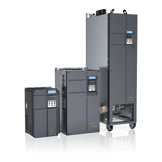
1 Product Information 1.2 Components The AC drive has either a plastic housing (three-phase 380 to 480 V, 0.4 to 15 kW models and three-phase 200 to 240 V, 0.4 to 7.5 kW models used as an example) or a sheet metal housing (200 to 450 kW models used as an example), depending on the voltage and power rating, as shown in the following figures. - Page 15 1 Product Information Figure 1-3 Components (Three-phase 380–480 V, MD290T200G to MD290T450G, MD290T220P to MD290T500P) - 14 -...
-
Page 16: Technical Data
1 Product Information 1.3 Technical Data Table 1-1 MD290TXXP models and technical data (three-phase 380–480 V) Item Specification MD290TXXP 18.5 Applicable 0.75 18.5 Motor (kW) Rated Output Current (A) Output 0 to input voltage Voltage Output Maximum Output 500 Hz (editable through a parameter) Frequency Carrier 0.8 to 8.0 kHz (automatically adjusted according to the temperature) - Page 17 1 Product Information Item Specification MD290TXXP Rated Input Current (A) Rated Input Three-phase 380 to 480 VAC, 50/60 Hz Voltage Allowed Voltage -15% to +10%; actual allowed range: 323–528 VAC Input Fluctuation Allowed Frequency ±5% Fluctuation Power Capacity (kVA) Thermal Power 1.22 1.61...
- Page 18 1 Product Information Item Specification MD290-2TXXP 18.5 Thermal Power 0.060 0.088 0.112 0.140 0.207 0.273 0.491 0.561 0.76 0.85 1.04 1.22 1.61 1.91 2.22 2.67 Thermal Consumption (kW) Design Air Flow 57.4 118.5 118.5 122.2 122.2 218.6 287.2 354.2 (CFM) IP Rating IP20 ◆...
- Page 19 1 Product Information Item Specification MD290TXXG Applicable Motor (kW) Rated Output Current (A) Output Three-phase 380 to 480 V (proportional to input voltage) Voltage Maximum Output Output 500 Hz (editable through a parameter) Frequency 0.8–8.0 kHz 0.8–6.0 kHz Carrier frequency Automatically adjusted according to the temperature Overload 150% for 60s with rated current (MD290T450G: 130% for 60s with rated current)
- Page 20 1 Product Information Table 1-4 MD290-2TXXG models and technical data (three-phase 200–240 V) Item Specification MD290-2TXXG 18.5 Applicable 0.75 18.5 Motor (kW) Rated Output 13.0 25.0 32.0 Current (A) Output 0 to input voltage Voltage Output Maximum Output 500 Hz (editable through a parameter) Frequency Carrier 0.8 to 8.0 kHz (automatically adjusted according to the temperature)
- Page 21 1 Product Information Table 1-5 Technical specifications of the MD290 series AC drive Item Specification Input frequency Digital setting: 0.01 Hz resolution Analog setting: Max. frequency x 0.025% Control mode Voltage/Frequency (V/F) control Torque boost Automatic boost; customized boost 0.1 % to 30.0 %...
- Page 22 1 Product Information Item Specification Allows different methods of switching between running commands: ◆ Operating panel (keypad & display) Running command ◆ Terminal I/O control ◆ Serial communication Supports up to 10 frequency reference setting channels and allows different methods of switching between frequency reference setting channels: Main frequency ◆...
- Page 23 Altitude Max. 3000 m (Note: The maximum altitude for 0.4 to 3 kW AC drives is 2000 m. For use at altitude over 2000 m, contact Inovance.) -10° C to + 40° C. Ambient If the ambient temperature is not in this range, de-rating by 1.5% per 1° C...
-
Page 24: Overall Dimensions
1 Product Information 1.4 Overall Dimensions 1.4.1 Overall Dimensions of MD290T0.4G/0.7PB to MD290T160G/200P and MD290-2T0.4G/0.7PB to MD290-2T55G/75P Figure 1-4 Overall and mounting dimensions of MD290T0.4G/0.7PB to MD290T37G/45P(B) and MD290-2T0.4G/0.7PB to MD290-2T18.5G/22P(B) Figure 1-5 Overall and mounting dimensions of MD290T45G/55P(B) to MD290T160G/200P and MD290-2T22G/30P(B) to MD290-2T55G/75P - 23 -... - Page 25 1 Product Information Table 1-6 Mounting hole dimensions of MD290T0.4G/0.7PB to MD290T160G/200P Hole Dimensions (mm) Overall Dimensions (mm) Hole Diameter (mm) AC Drive Model Weight (kg) MD290T0.4G/0.7PB MD290T0.7G/1.1PB MD290T1.1G/1.5PB Ø5 MD290T1.5G/2.2PB MD290T2.2G/3.0PB MD290T3.0G/3.7PB MD290T3.7G/5.5PB Ø5 MD290T5.5G/7.5PB MD290T7.5G/11PB Ø6 MD290T11G/15PB MD290T15G/18.5PB Ø6 MD290T18.5G/22P(B) Ø6 MD290T22G/30P(B)
-
Page 26: Overall Dimensions Of Md290T200G To Md290T450G And Md290T220P To Md290T500P
1 Product Information 1.4.2 Overall Dimensions of MD290T200G to MD290T450G and MD290T220P to MD290T500P Figure 1-6 Overall and mounting dimensions of MD290T200G to MD290T450G and MD290T220P to MD290T500P Table 1-8 Mounting hole dimensions of MD290T200G to MD290T450G and MD290T220P to MD290T500P Hole Hole Dimensions (mm) Overall Dimensions (mm) Diameter... -
Page 27: Overall Dimensions Of Md290T200G-L To Md290T450G-L And Md290T220P-L To Md290T500P-L
1 Product Information 1.4.3 Overall Dimensions of MD290T200G-L to MD290T450G-L and MD290T220P-L to MD290T500P-L Figure 1-7 Overall and mounting dimensions of MD290T200G-L to MD290T450G-L and MD290T220P-L to MD290T500P-L Table 1-9 Mounting hole dimensions of MD290T200G-L to MD290T450G-L and MD290T220P-L to MD290T500P-L (with the reactor base) Hole Hole Dimensions (mm) Overall Dimensions (mm) -
Page 28: System Connections
Ground Figure 2-1 MD290 series system composition ◆ The preceding figure is just a schematic system connection diagram of the MD290 series AC drive. For peripherals and options, see 19010321 MD290 Series AC Drive Advanced User Guide. NOTE - 27 -... -
Page 29: System Structure
2 System Connections 2.2 System Structure Table 2-1 Description of peripheral electrical devices in the MD290 series AC drive system Device Mounting Location Function Description MCCB: Cuts off power supply when overcurrent Between the occurs on downstream devices. Breaker power supply and... - Page 30 2 System Connections Device Mounting Location Function Description The output side of the AC drive generally has much higher harmonics. When the motor is far from the AC drive, there is much distributed capacitance in the circuit and certain harmonics may cause Between the AC resonance in the circuit, which will: drive output side...
-
Page 31: Options
2 System Connections 2.3 Options Peripherals and options include braking units, function extension cards, and external operating panel, as listed in the following table. For use of each option, see its user guide. If you need to purchase the following options, specify the required option in the order. - Page 32 User User programmable extension card Available for programmable MD38PC1 Compatible with H1U-series PLCs of models of 15 kW or card Inovance above Parameter copy External LCD External LCD display and operating MDKE9 and download operating panel panel supported...
-
Page 33: Selection Of Cables, Breakers, And Contactors
2 System Connections 2.4 Selection of Cables, Breakers, and Contactors Table 2-3 Selection of cables, breakers, and contactors (three-phase 380–480 V) Recommended Recom- Recom- Fuse Bussmann mended Terminal RST/UVW Ground Cable mended Passed UL Contac- Width Breaker Certification Model of the Screw Recom- Recom-... - Page 34 2 System Connections Recommended Recom- Recom- Fuse Bussmann mended RST/UVW Ground Cable Terminal mended Passed UL Contac- Width Breaker Certification Model of the Screw Recom- Recom- Recom- Recom- AC Drive Rated Rated Rated mended mended mended Lug mended (mm) Current Model Current Current...
- Page 35 2 System Connections Terminal RST/UVW Ground Cable Width of Model Screw the AC Drive Recommended Recommended Recommended Cable Recommended (mm) Cable (AWG/mil) Lug Model (AWG/kcmil) Lug Model MD290T315P(-L) 2×500 SQNBS325-16 SQNBS325-16 MD290T315G(-L) 2×600 SQNBS325-16 SQNBS325-16 MD290T355P(-L) 2×500 TLK300-16 TLK300-16 MD290T355G(-L) 2×600 TLK400-16 TLK400-16...
-
Page 36: Selection Of The Ac Output Reactor
200–500 ≧ 11 200–500 200–500 Table 2-8 Recommended models of the AC output reactor (three phase 380–480 V) AC Output Reactor Model AC Output Reactor Model AC Drive Model AC Drive Model (Inovance) (Inovance) MD290T0.4G/0.7PB MD-OCL-5-1.4-4T-1% MD290T18.5G/22P(B) MD-OCL-50-0.14-4T-1% MD290T0.7G/1.1PB MD-OCL-5-1.4-4T-1% MD290T22G/30P(B) MD-OCL-60-0.12-4T-1%... -
Page 37: Selection Of Braking Components
2 System Connections AC Output Reactor Model AC Output Reactor Model AC Drive Model AC Drive Model (Inovance) (Inovance) MD290-2T1.5G/2.2PB MD-OCL-10-0.7-4T-1% MD290-2T22G/30P(B) MD-OCL-120-0.058-4T-1% MD290-2T2.2G/3.7PB MD-OCL-15-0.47-4T-1% MD290-2T30G/37P(B) MD-OCL-150-0.047-4T-1% MD290-2T3.7G/5.5PB MD-OCL-20-0.35-4T-1% MD290-2T37G/45P(B) MD-OCL-200-0.035-4T-1% MD290-2T5.5G/7.5PB MD-OCL-40-0.18-4T-1% MD290-2T45G/55P MD-OCL-250-0.028-4T-1% MD290-2T7.5G/11PB MD-OCL-40-0.18-4T-1% MD290-2T55G/75P MD-OCL-330-0.021-4T-1% ◆ Use AC output reactors of MD290T200G-L to MD290T450G-L for AC drives MD290T200G to MD290T450G. - Page 38 2 System Connections 125% Braking Torque Braking Unit Minimum (10% ED, Max. 10s) Applicable Braking AC Drive Model Remarks Motor (kW) Resistance Recommended Model (Ω) Braking Resistor MDBUN-90-T 16000 W 6.3 Ω Input voltage ≤ 440 VAC 6.2×2 MD290T160G/200P MDBUN-90-5T 16000 W 7.2 Ω...
- Page 39 2 System Connections Table 2-11 Braking component selection (three phase 200–240 V) 125% Braking Torque Minimum Braking Unit (10% ED, Max. 10s) Applicable Braking AC Drive Model Remarks Motor (kW) Resistance Recommended Model (Ω) Braking Resistor MD290-2T0.4G/0.7PB 0.75 220 W 500 Ω MD290-2T0.7G/1.1PB 440 W 260 Ω...
-
Page 40: External Operating Panels
MDKE9 is an optional external LCD operating panel. It supports copy, download, and modification of all parameters and is easy to use in both Chinese and English. The following figure shows its appearance and keys. (For details, see 19010321 MD290 Series AC Drive Advanced User Guide.) - Page 41 2 System Connections 26.4 MDKE9 Figure 2-4 Mounting dimensions of the MDKE9 external operating panel (unit: mm) 3) MDKE9 mounting base Before installing the MDKE9 operating panel on the cabinet door, install the CP600- BASE1 (optional) base first. The mounting dimensions are shown below. 53.3 Figure 2-5 Sheet metal slot dimensions (unit: mm) - 40 -...
- Page 42 2 System Connections 27.5 27.5 46.8 46.8 Figure 2-6 Mounting base dimension limits (unit: mm) - 41 -...
-
Page 43: Installation And Wiring
3 Installation and Wiring 3 Installation and Wiring 3.1 Installation 3.1.1 Installation Environment 1) Ambient temperature: The AC drive's service life is greatly influenced by the ambient temperature. Do not run the AC drive under a temperature exceeding the allowed temperature range (-10℃ to +50℃ ). 2) Install the AC drive on a flame-retardant surface, and ensure that sufficient space is left around the enclosure to allow for efficient heat dissipation. -
Page 44: Backplate Mounting And Through-Hole Mounting
3 Installation and Wiring 3.1.2 Backplate Mounting and Through-Hole Mounting 1) Backplate mounting Figure 3-2 Backplate mounting of MD290T0.4G/0.7PB to MD290T37G/45P(B) and MD290- 2T0.4G/0.7PB to MD290-2T18.5G/22P(B) Hoisting ring Mounting hole Figure 3-3 Backplate mounting of MD290T45G/55P(B) to MD290T160G/200P and MD290- 2T22G/30P(B) to MD290-2T55G/75P ◆... - Page 45 3 Installation and Wiring 2) Through-hole mounting Fit the bracket to the housing and secure screws The mounting bracket is mounted. at both sides. Through-hole mounting bracket Secure the AC drive to the rear of the The AC drive is mounted. supporting surface.
- Page 46 3 Installation and Wiring The mounting bracket is Secure the through-hole mounting brackets to the mounted. left and right of the housing. Through-hole mounting bracket Through-hole mounting bracket Secure the AC drive to the front of the supporting The AC drive is mounted. surface.
-
Page 47: Mounting In The Cabinet
3 Installation and Wiring 3) Through-hole mounting brackets Table 3-1 Through-hole mounting bracket models (three phase 380–480 V) Through-hole Through-hole Mounting Bracket AC Drive Model Mounting Bracket AC Drive Model Model Model MD290T18.5G/22P(B) MD290T0.4G/0.7PB (-T) MD500-AZJ-A1T5 MD290T0.7G/1.1PB MD290T22G/30P(B)(-T) MD290T1.1G/1.5PB MD290T30G/37P(B) MD500-AZJ-A1T1 MD500-AZJ-A1T6 MD290T1.5G/2.2PB MD290T37G/45P(B) - Page 48 3 Installation and Wiring ■ Direct discharging cabinet (without fans on the top) Cabinet top air outlet cover Ventilation airflow Isolation barrier 2200 450 kW model Air inlet of front door Figure 3-6 Direct discharging cabinet Table 3-3 Specification of the direct discharging cabinet Effective Area of Effective Area of Quantity...
- Page 49 3 Installation and Wiring ■ Cabinet with fans on the top Ventilation airflow Isolation barrier 2200 450 kW model Air inlet of front door Figure 3-7 Cabinet with fans on the top Table 3-4 Specification of the cabinet with fans on the top Effective Max.
-
Page 50: Wiring
3 Installation and Wiring 3.2 Wiring 3.2.1 Standard Wiring Diagram As shown in the following figure, the wiring part marked by the double-headed arrow differs between three-phase 380 to 480 V 0.4G/0.7PB to 75G/90P(B) models and 90G/100P to 450G/500P models, and between three-phase 200 to 240 V 0.4G/0.7PB to 37G/45P(B) models and 45G/55P and above models. -
Page 51: Main Circuit Terminals
3 Installation and Wiring 3.2.2 Main Circuit Terminals Figure 3-9 Terminal arrangement in MD290T0.4G/0.7PB to MD290T15G/18.5PB and MD290- 2T0.4G/0.7PB to MD290-2T7.5G/11PB R S T U V W BR (+) (-) POWER MOTOR Figure 3-10 Terminal arrangement in MD290T18.5G/22P(B) to MD290T160G/200P and MD290- 2T11G/15P(B) to MD290-2T55G/75P (Front view) (Side view) -
Page 52: Control Circuit Terminals
3 Installation and Wiring Table 3-5 Description of main circuit terminals Terminal Name Description Three-phase power R, S, T Connected to AC input three-phase power supply. supply input terminals DC bus positive and Common DC bus input, connected to the external (+), (-) negative terminals braking unit for AC drives of 90 kW and above... - Page 53 3 Installation and Wiring Table 3-6 Description of control circuit terminals Terminal Type Terminal Name Description Mark Provides +10 V power supply to an external unit. Its +10 V power maximum output current is 10 mA. V-GND supply Generally used to supply an external potentiometer of 1 to 5 kΩ...
- Page 54 3 Installation and Wiring Terminal Type Terminal Name Description Mark Optically-coupled isolation, dual-polarity open- collector output Output voltage range: 0 to 24 V Output current range: 0 to 50 mA DO1-CME Digital output 1 Note that CME and COM are internally insulated, but are shorted externally by a jumper.
- Page 55 3 Installation and Wiring Power grid system requirements: ◆ The AC drive is applicable to power grid systems with neutral points grounded. If the AC drive is used in an IT power system (where the neutral point is not grounded), screws 1 and 2 shown in the following figure must be screwed out to remove the jumpers of the voltage-dependent resistor (VDR) and EMC.
-
Page 56: Panel Operations
The LED operating panel allows you to set and modify parameters, monitor system status, and start or stop the AC drive. For details, see 19010321 MD290 Series AC Drive Advanced User Guide. An external LED (MD32NKE1) or LCD (MDKE9) operating panel is also available as an option. -
Page 57: Indicators On The Operating Panel
4 Panel Operations Name Function Stop the AC drive when the AC drive is in the RUNNING status. Stop/Reset STOP Perform a reset operation when the AC drive is in the FAULT status. Perform a function switchover as defined by the setting of F7-01 Multifunction (MF.K key function selection). -
Page 58: Basic Operations And Trial Run
Set motor parameters in group F1. Confirm that the motor can be safely started up. Press "RUN" to run the (Step 4: See 19010321 MD290 Series AC Drive motor. Check whether the running current and running direction are normal Advanced User Guide.) in both no-load and with-load running. -
Page 59: Status Display After Power-On
5 Basic Operations and Trial Run 5.3 Status Display After Power-on The following table lists the display on the operating panel after the AC drive is powered State Display Description Normal The default value 50.00 Hz is displayed. Fault The AC drive stops and displays an error code. 5.4 Parameter Initialization You can restore the AC drive to factory parameters. -
Page 60: Motor Control Modes
5 Basic Operations and Trial Run 5.5 Motor Control Modes Parameter Description Scenario F0-01: Motor F0-01 = 2: V/F control It is applicable to scenarios having no high control (open-loop speed requirement on load (fans and pumps) or using mode control) one AC drive to drive multiple motors. - Page 61 5 Basic Operations and Trial Run Motor Parameter F1-00: Motor type selection F1-01: Rated motor power Motor 1 F1-02: Rated motor voltage F1-03: Rated motor current F1-04: Rated motor frequency F1-05: Rated motor speed A2-00 (Motor type selection) to A2-05 (Rated motor speed) have the same Motor 2 definition.
-
Page 62: Troubleshooting
6 Troubleshooting 6 Troubleshooting 6.1 Fault Codes and Solutions Troubleshoot the faults occurred during operating the AC drive as follows. Fault Fault Name Possible Cause Solution Code A grounding fault or Check whether short-circuit occurs on short circuit exists in the the motor or contactor. - Page 63 6 Troubleshooting Fault Fault Name Possible Cause Solution Code A grounding fault or Check whether short-circuit or open- short circuit exists in the circuit occurs on the motor. output circuit. The deceleration time is Increase the deceleration time. too short. Ensure that current limit is enabled (F3- 19 = 1).
- Page 64 6 Troubleshooting Fault Fault Name Possible Cause Solution Code The input voltage is too Adjust the input voltage to the normal high. range. An external force drives Cancel the external force or install a the motor during braking resistor. acceleration. Ensure that the voltage limit function is enabled (F3-23 = 1).
- Page 65 Adjust the voltage to the normal range. permissible range. Err09 Undervoltage The bus voltage is Contact the agent or Inovance. abnormal. The rectifier bridge, pre- charge resistor, drive Contact the agent or Inovance. board, or control board is abnormal.
- Page 66 6 Troubleshooting Fault Fault Name Possible Cause Solution Code The ambient Lower the ambient temperature. temperature is too high. The ventilation is Clean the ventilation. clogged. Err14 IGBT overheat The fan is damaged. Replace the cooling fan. The thermistor of IGBT Replace the thermistor.
- Page 67 6 Troubleshooting Fault Fault Name Possible Cause Solution Code Motor parameters are Set motor parameters correctly not set according to the according to the nameplate. Motor auto- nameplate. Err19 tuning fault Motor auto-tuning times Check whether the AC drive and motor out.
-
Page 68: Common Symptoms And Solutions
Err61 braking resistor is too overload resistance. low. Short-circuit of The braking module is Err62 Contact the agent or Inovance. braking circuit abnormal. 6.2 Common Symptoms and Solutions Fault Symptom Possible Cause Solution There is no power supply to the AC drive or the power Check the power supply. - Page 69 " " control board are damaged. upon power-on. The motor or motor cable is Contact the agent or Inovance. short-circuited to ground. The Hall element is faulty. The mains voltage is too low. The motor or the motor Check the insulation status of the...
- Page 70 ◆ Check whether 24 V power running. supply of the contactor is faulty. ◆ Contact the agent or Inovance. The brake torque of the motor is insufficient when If the braking resistor has been The overvoltage stall...
-
Page 71: Maintenance
7 Maintenance 7 Maintenance 7.1 Routine Maintenance Check the following items daily to ensure normal running and prevent damage to the AC drive. Copy this checklist and sign the "Checked" column after each inspection. Inspection Inspection Points Solutions Checked Item ◆... -
Page 72: Periodic Inspection
7 Maintenance 7.2 Periodic Inspection Inspection Inspection Point Solution Checked Item ◆ Check whether the cabinet of the AC drive is powered off. ◆ Use a vacuum cleaner to Inspect for wastes, dirt, and dust on General suck up wastes and dust to the surface of the AC drive. -
Page 73: Replacing Cooling Fans
7 Maintenance 7.3.2 Replacing Cooling Fans 1) Possible damage causes: bearing worn and blade aging 2) Replacement determination criteria: whether there is crack on the blade; whether there is abnormal vibration noise upon startup; whether the blade runs abnormally 3) Replacement notes: ■... -
Page 74: Storage
For storage of the AC drive, pay attention to the following three aspects: 1) Pack the AC drive with the original packing box provided by Inovance. 2) Do not expose the AC drive to moisture, high temperature or outdoor direct sunlight for an extended period. -
Page 75: Appendix A Parameter Table
Appendix A Parameter Table Appendix A Parameter Table ☆ : It is possible to modify the parameter with the AC drive in the Stop and in the Run status. ★ : It is not possible to modify the parameter with the AC drive in the Run status. ●... - Page 76 Appendix A Parameter Table Param. Name Setting Range Default Change Frequency reference upper F0-12 F0-14 (Frequency reference lower limit) to F0-10 (Max. frequency) 50.00 Hz ☆ limit Frequency reference upper F0-13 0.00 Hz to F0-10 (Max. frequency) 0.00 Hz ☆ limit offset Frequency reference lower F0-14...
- Page 77 Appendix A Parameter Table Param. Name Setting Range Default Change 0.01 A to 655.35 A (AC drive power ≤ 55 kW) Model F1-03 Rated motor current ★ 0.1 A to 6553.5 A (AC drive power > 55 kW) dependent Model F1-04 Rated motor frequency 0.01 Hz to max.
- Page 78 Appendix A Parameter Table Param. Name Setting Range Default Change F3-20 Current limit gain 0 to 100 ☆ Compensation factor of F3-21 speed multiplying current 50% to 200% ★ limit Three phase 380 to 480 V models: 330.0 to 800.0 V F3-22 Voltage limit 770.0 V ★...
- Page 79 Appendix A Parameter Table Param. Name Setting Range Default Change Corresponding percentage F4-14 -100.0% to +100.0% 0.0% ☆ of AI curve 1 min. input F4-15 AI curve 1 max. input F4-13 (AI curve 1 min. input) to 10.00 V 10.00 V ☆...
- Page 80 Appendix A Parameter Table Param. Name Setting Range Default Change F4-35 DI1 delay 0.0s to 3600.0s 0.0s ★ F4-36 DI2 delay 0.0s to 3600.0s 0.0s ★ F4-37 DI3 delay 0.0s to 3600.0s 0.0s ★ Ten Thousands: DI5 active mode 0: High level active 1: Low level active Thousands: DI4 active mode...
- Page 81 Appendix A Parameter Table Param. Name Setting Range Default Change 0: No output 23: Zero-speed running 2 1: AC drive running (having output at stop) 2: Fault output (coast to stop) 24: Accumulative power-on F5-01 FMR function selection ☆ 3: Frequency-level detection FDT1 time reached output 25: Frequency level detection...
- Page 82 Appendix A Parameter Table Param. Name Setting Range Default Change Ten thousands: DO2 active mode 0: Positive logic active 1: Negative logic active Thousands: DO1 active mode Active mode selection of DO 0: Positive logic active F5-22 00000 ☆ 1: Negative logic active output terminals Hundreds: Relay2 active mode...
- Page 83 Appendix A Parameter Table Param. Name Setting Range Default Change Group F7: Operating Panel and Display 0: MF.K key disabled 2: Switchover between forward 1: Switchover from remote control rotation and reverse rotation F7-01 MF.K key function selection ★ (terminal or communication) to 3: Forward jog operating panel control 4: Reverse jog...
- Page 84 Appendix A Parameter Table Param. Name Setting Range Default Change 0000 to FFFF Frequency reference (Hz) Bus voltage (V) DI state DO state AI1 voltage (V) AI2 voltage (V) LED display stop AI3 voltage (V) F7-05 ☆ parameters Count value 12 11 10 9 Length value...
- Page 85 Appendix A Parameter Table Param. Name Setting Range Default Change F8-09 Frequency jump 1 0.00 Hz to the maximum frequency 0.00 Hz ☆ F8-10 Frequency jump 2 0.00 Hz to the maximum frequency 0.00 Hz ☆ F8-11 Frequency jump band 0.00 Hz to the maximum frequency 0.00 Hz ☆...
- Page 86 Appendix A Parameter Table Param. Name Setting Range Default Change AI1 input voltage lower F8-45 0.00 V to F8-46 (AI1 input voltage upper limit) 3.10 V ☆ limit AI1 input voltage upper F8-46 F8-45 (AI1 input voltage lower limit) to 10.00 V 6.80 V ☆...
- Page 87 Appendix A Parameter Table Param. Name Setting Range Default Change Output phase loss Tens: Output phase loss protection F9-13 ☆ before running protection 0: Disabled 1: Enabled Ones: Output phase loss protection 0: Disabled 1: Enabled 0: No fault 23: Motor short circuited to 1: Reserved ground 2: Overcurrent during acceleration...
- Page 88 Appendix A Parameter Table Param. Name Setting Range Default Change F9-41 DO state upon 1st fault 0 to 9999 ● AC drive state upon 1st F9-42 0 to 65535 ● fault Power-on time upon 1st F9-43 0s to 65535s ● fault Running time upon 1st F9-44...
- Page 89 Appendix A Parameter Table Param. Name Setting Range Default Change Type of motor temperature 1: PT100 F9-56 0: No temperature sensor ☆ sensor 2: PT1000 Motor overheat protection F9-57 0℃ to 200℃ 110℃ ☆ threshold Motor overheat pre- F9-58 0℃ to 200℃ 90℃...
- Page 90 Appendix A Parameter Table Param. Name Setting Range Default Change 0: No switchover PID parameter switchover 1: Switchover using DI 3: Auto switchover based on FA-18 ☆ condition 2: Auto switchover based on PID running frequency error PID error 1 for auto FA-19 0.0% to FA-20 (PID error 2 for auto switchover) 20.0%...
- Page 91 Appendix A Parameter Table Param. Name Setting Range Default Change Simple PLC retentive Tens: Retentive at stop FC-17 ☆ 0: Not retentive at stop selection 1: Retentive at stop Ones: Retentive at power down 0: Not retentive 1: Retentive Running time of simple PLC FC-18 0.0s (h) to 6553.5s (h) 0.0s (h)
- Page 92 Appendix A Parameter Table Param. Name Setting Range Default Change Acceleration/Deceleration FC-37 time of simple PLC 0 to 3 ☆ reference 9 Running time of simple PLC FC-38 0.0s (h) to 6553.5s (h) 0.0s (h) ☆ reference 10 Acceleration/Deceleration FC-39 time of simple PLC 0 to 3 ☆...
- Page 93 Appendix A Parameter Table Param. Name Setting Range Default Change 0: No check (8,N,2) Modbus data format 3: No check (8,N,1) FD-01 1: Even parity check (8,E,1) ☆ symbol (Valid for Modbus) 2: Odd parity check (8,O,1) 0: Broadcast address; FD-02 Local address ☆...
- Page 94 Appendix A Parameter Table Param. Name Setting Range Default Change 0: No operation 04: Back up current user 01: Restore factory parameters parameters FP-01 Parameter initialization ★ except motor parameters 501: Restore user backup 02: Clear records parameters Ten: Group A FP-02 Parameter display property ★...
- Page 95 Appendix A Parameter Table Param. Name Setting Range Default Change Function selection for AI1 A1-07 0 to 59 ★ used as DI Function selection for AI2 A1-08 0 to 59 ★ used as DI Function selection for AI3 A1-09 0 to 59 ★...
- Page 96 Appendix A Parameter Table Param. Name Setting Range Default Change Model A2-05 Rated motor speed 1 rpm to 65535 rpm ★ dependent 0.001 Ω to 65.535 Ω (AC drive power ≤ 55 kW) Model A2-06 Stator resistance ★ 0.0001 Ω to 6.5535 Ω (AC drive power > 55 kW) dependent 0.001 Ω...
- Page 97 Appendix A Parameter Table Param. Name Setting Range Default Change Corresponding percentage A6-09 -100.0% to +100.0% -100.0% ☆ of AI curve 5 min. input A6-10 AI curve 5 inflection 1 input A6-08 (AI curve 5 min. input) to A6-12 (AI curve 5 inflection 2 input) -3.00 V ☆...
- Page 98 Appendix A Parameter Table Param. Name Setting Range Default Change Hundreds: DO 0: Disabled Selection of PLC program 1: Enabled A7-05 ☆ controlling digital output Tens: Relay 1 0: Disabled 1: Enabled Ones: FMR 0: Disabled 1: Enabled Setting frequency A7-06 reference using the user -100.00% to 100.00%...
- Page 99 Appendix A Parameter Table Param. Name Setting Range Default Change Factory- AC-02 AI1 measured voltage 2 6.000 V to 9.999 V ☆ corrected Factory- AC-03 AI1 displayed voltage 2 6.000 V to 9.999 V ☆ corrected Factory- AC-04 AI2 measured voltage 1 0.500 V to 4.000 V ☆...
-
Page 100: Monitoring Parameters
Appendix A Parameter Table A.2 Monitoring Parameters Communication Param. Name Minimum Unit Address Group U0: Monitoring Parameters U0-00 Running frequency 0.01 Hz 7000H U0-01 Frequency reference 0.01 Hz 7001H U0-02 Bus voltage 0.1 V 7002H U0-03 Output voltage 7003H U0-04 Output current 0.01 A 7004H... - Page 101 Appendix A Parameter Table Communication Param. Name Minimum Unit Address DI set for function state display 2 U0-44 702CH (function 41-80) U0-45 Fault information 702DH U0-59 Rated frequency 0.01% 703BH U0-60 Running frequency 0.01% 703CH U0-61 AC drive state 703DH U0-62 Current fault code 703EH...
-
Page 102: Warranty Agreement
Warranty Agreement Warranty Agreement 1) Inovance provides an 18-month free warranty to the equipment itself from the date of manufacturing for the failure or damage under normal use conditions. 2) Within the warranty period, maintenance will be charged for the damage caused by the following reasons: a. - Page 103 Service Hotline: 400-777-1260 http: //www.inovance.com Suzhou Inovance Technology Co., Ltd. Add.: No. 16 Youxiang Road, Yuexi Town, Wuzhong District, Suzhou 215104, P.R. China Tel: +86-512-6637 6666 Fax: +86-512-6285 6720 Service Hotline: 400-777-1260 http: //www.inovance.com Copyright Shenzhen Inovance Technology Co., Ltd.
Need help?
Do you have a question about the MD290 Series and is the answer not in the manual?
Questions and answers