Table of Contents
Advertisement
Quick Links
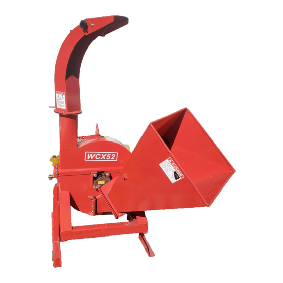
WCX52 WOOD CHIPPER
Rugged Labor Saving Equipment Since 1995
OPERATION & PARTS MANUAL
Please read these instructions carefully before using! Always grease all
fittings and be sure to always check and fill with oil before operating!
Retain this manual for future reference.
Specifications subject to change without notice.
Specifications subject to change without notice.
Advertisement
Table of Contents

Related Manuals for Betstco FHM WCX52

Summary of Contents for Betstco FHM WCX52
- Page 1 WCX52 WOOD CHIPPER Rugged Labor Saving Equipment Since 1995 OPERATION & PARTS MANUAL Please read these instructions carefully before using! Always grease all fittings and be sure to always check and fill with oil before operating! Retain this manual for future reference. Specifications subject to change without notice.
- Page 2 ASSEMBLY INSTRUCTION...
- Page 3 ASSEMBLY INSTRUCTION...
- Page 4 ASSEMBLY INSTRUCTION...
- Page 5 ASSEMBLY INSTRUCTION...
- Page 6 ASSEMBLY INSTRUCTION Contact our support desk for any questions or concerns at (541)895-3083...
- Page 7 INTRODUCTION Congratulations on your choice of a Farmer Helper 3 Point Hitch Wood Chipper to compliment your operation. This equipment has been designed and manufactured to meet the needs of a discerning timber or landscaping industry. Safe, efficient and trouble free operation of your Farmer Helper Wood Chipper requires that you and anyone else who will be using or maintaining the chipper, read and understand the Safety, Operation, Maintenance Trouble Shooting information contained within the Operator's Manual.
-
Page 8: Safety Alert Symbol
SAFETY SAFETY ALERT SYMBOL This Safety Alert symbol means The Safety Alert symbol identifies ATTENTION! BECOME ALERT! important safety messages on the Farmer Helper 3 Point Hitch Wood YOUR SAFETY IS INVOLVED! Chipper and in the manual. When you see this symbol, be alert to the possibility of personal injury or death. -
Page 9: General Safety
GENERAL SAFETY SAFETY 1. Read and understand the YOU are responsible for the SAFE operation and Operator’s Manual and all maintenance of your Farmer Helper 3 Point Hitch safety signs before using, Wood Chipper. YOU must ensure that you and maintaining, adjusting or anyone else who is going to use, maintain or work cleaning the... -
Page 10: Equipment Safety Guidelines
EQUIPMENT SAFETY GUIDELINES 1. Safety of the operator and bystanders is one of 7. Never exceed the limits of a piece of machinery. the main concerns in designing and developing If its ability to do a job, or to do so safely, is in equipment. -
Page 11: Safety Training
SAFETY TRAINING SAFETY SIGNS 1. Keep safety signs clean and legible at all 1. Safety is a primary concern in the design and manufacture of our products. Unfortunately, our times. efforts to provide safe equipment can be wiped 2. Replace safety signs that are missing or have out by a single careless act of an operator or bystander. -
Page 12: Maintenance Safety
MAINTENANCE SAFETY PREPARATION Good maintenance is your responsibility. Poor 1. Never use the machine until you have read and maintenance is an invitation to trouble. completely understand this manual, the tractor Operator's Manual and each of the Safety 1. Follow good shop practices. Messages found on the safety signs on the tractor and machine. - Page 13 2.7 OPERATING SAFETY 11. Use care when feeding material into chipper. Do 1. Please remember it is important that you read not send metal, bottles, cans, rocks, glass or and heed the safety signs on the 3 Point Hitch other foreign material into wood chipper. If Wood Chipper.
-
Page 14: Storage Safety
TRANSPORT SAFETY 2.8 STORAGE SAFETY 1. Store the unit in an area away from human 1. Comply with state and local laws governing activity. safety and transporting of machinery on public roads. 2. Do not children to play on or around the stored machine. -
Page 15: Safety Sign Locations
SAFETY SIGN LOCATIONS The types of safety signs and locations on the equipment are shown in the illustrations that follow. Good safety requires that you familiarize yourself with the various safety signs, the type of warning and the area, or particular function related to that area, that requires your SAFETY AWARENESS. •... - Page 16 The types of safety signs and locations on the equipment are shown in the illustrations that follow. Good safety requires that you familiarize yourself with the various safety signs, the type of warning and the area, or particular function related to that area, that requires your SAFETY AWARENESS. DANGER THROWN OBJECT HAZARD To prevent serious injury or death from...
- Page 17 The types of safety signs and locations on the equipment are shown in the illustrations that follow. Good safety requires that you familiarize yourself with the various safety signs, the type of warning and the area, or particular function related to that area, that requires your SAFETY AWARENESS. DANGER DANGER GUARDS MISSING...
- Page 18 ASSEMBLING FIG 1. The machine comes from the factory in a shipping WCX5 configuration. Always use tools equipment and forklifts of appropriate size and capacity for the job. Always use 2 men when lifting, moving and assembling the machine. When the machine is shipped, follow this procedure when preparing for the customer: 1.
- Page 19 6. Use a forklift to raise and lift the frame. Forklift 7. Or alternatively attach a lifting device to the lifting bracket on top of the frame. Bracket Fig. 3 LIFTING 8. Remove pallet and place machine on the ground. Fig.
- Page 20 9. Release feed hopper transport latch and lower hopper into the working position. Stow anchor latch. Fig. 5 HOPPER TRANSPORT LATCH 10. Tighten anchor bolts to their specified torque. Fig. 6 ANCHOR BOLTS (TYPICAL)
- Page 21 11. Connect the PTO drivline: a. Raise the input shaft guard. b. Check that the driveline telescopes easily and that the shield rotates freely. c. Attach the driveline to the chipper input shaft by depressing the lock pin, slide yoke over the shaft and pushing on the yoke until the lock pin clicks into position.
-
Page 22: Operation
OPERATION OPERATING SAFETY • Never use alcoholic beverages or drugs • Please remember it is important that you read which can hinder alertness or coordination the operator's manual and heed the safety while operating this equipment. Consult signs on the 3 Point Hitch Wood Chipper. your doctor about operating this machine They are there for your safety, as well as the while taking prescription medications. -
Page 23: Machine Components
5.2 MACHINE COMPONENTS Fig. 9 PRINCIPLE COMPONENTS The Farmer Helper 3 Point Hitch Wood Chipper is a rotor with blades for chipping wood. A hinged feed hopper moves the wood material into the rotor. Each rotor is designed with 4 blades and a twig-breaker to generate the small pieces of wood. -
Page 24: Machine Break-In
5.4 PRE-OPERATION CHECKLIST 5.3 MACHINE BREAK-IN Although there are no operational restrictions on Efficient and safe operation of the Farmer Helper 3 the Wood Chipper when used for the first time, Point Hitch Wood Chipper requires that each it is recommended that the following mechanical operator reads and understands the using items be checked: procedures and all related safety precautions... -
Page 25: Driveline Dimension
5.5 DRIVELINE DIMENSION A PTO driveline is supplied with the machine to accompany the variety of 3 point hitch geometry available today, the driveline can be too long for most machines or too short for others. It is very important that the driveline be free to telescope but not to bottom out when going through its working range. - Page 26 5.6 MOUNTING AND UNHOOKING TRACTOR When attaching chipper to a tractor, follow this procedure: 1. Clear the area of bystanders, especially small children. 2. Make sure there is enough room and clearance to safely back up to the chipper. 3. Place the tractor arms in their full sway position.
- Page 27 8. Slowly raise the machine through its working 5. Mounting with a Quick Hitch. range to make sure the telescoping portion of the PTO shaft doesn't bottom out. a. Align the claws on the Quick Hitch slightly below the mounting pins on the chipper. 9.
- Page 28 Deflector Position: Each discharge hood is equipped with a deflector on the end to place the chips exactly where desired. Manual Clamp (WCX52): The deflector is held in place by clamping bolts on each side. Loosen the clamps, move the deflector and tighten PTO Control: If you are not familiar with the location of the Manual Clamp...
-
Page 29: Field Operation
5. 7 FIELD OPERATION OPERATING SAFETY • Please remember it is important that you read • Never use alcoholic beverages or drugs the operator's manual and heed the safety which can hinder alertness or coordination signs on the 3 Point Hitch Wood Chipper. while operating this equipment. - Page 30 1. Starting the Machine: a. Start the tractor engine. b. Move the throttle to its low idle position. c. With the engine at low idle, slowly engage the PTO control. d. Slowly increase the engine speed until the PTO is at rated speed. e.
- Page 31 3. Emergency Stopping: Stop tractor engine if an emergency occurs. Correct emergency situation before starting engine and resuming work. 4. Feeding: a. Manual Feed: • Slowly slide the wooden material into the feed hopper and move it into the rotor. •...
- Page 32 7. Blades: There are 2 types of blades used on the Wood Chipper. They work together to cut, shear and shred the wood as it moves through the machine. a. Rotor blades: The rotor is equipped with 4 blades placed at 90° to each other to keep the rotor in balance.
- Page 33 9. Twig Breaker: Each machine is equipped with a twig breaker to break up twigs or other long material as it moves through the rotor compartment. Open the rotor cover and check the condition of the breaker on a weekly basis. Also check for any entangled material when the rotor cover is opened.
- Page 34 10. Shear Pin: The PTO driveline is designed with a shear pin at the input yoke to prevent overloading the drive system. Remove the broken parts from the yoke when the pin shears and replace with genuine Farmer Helper parts. The drive system is designed to function well without failing the shear pin.
- Page 35 11. Unplugging: Although the machine is designed to handle a wide variety of material without any problem, occasionally it plugs. When the machine plugs, follow this procedure to unplug: a. Clear the area of bystanders, especially small children. b. Stop the engine, remove the ignition key and place it in your pocket and wait for all moving parts to stop before unplugging.
- Page 36 14. Sharpening Blades: The rotor and stationary blades need to be sharp for the chipper to perform as expected. It is recommended that the rotor blades be removed from the rotor when sharpening. Always sharpen the blades at a 45° angle to provide the best cutting effect as it meets the stationary blade.
- Page 37 15 . Personal Protective Equipment (PPE): Each person must wear appropriate personal protective equipment whenever operating the chipper or working in the vicinity. This equipment is designed to prevent injury to any personnel in the area. This list includes but is not limited to: •...
-
Page 38: Transport Safety
5.9 TRANSPORTING TRANSPORT SAFETY 1. Comply with state and local laws governing 5. Be sure the trailer is hitched positively to safety and transporting of machinery on the towing vehicle and a retainer is used public roads. through the mounting pins. 6. -
Page 39: Placing In Storage
5.10 STORAGE 3. Inspect all rotating parts for entangled OPERATING SAFETY material. Remove all entangled material. 4. Run the machine a few minutes to dry the • Store the unit in an area away from human moisture from inside the machine. activity. -
Page 40: Servicing Intervals
SERVICING INTERVALS The period recommended is based on normal operating conditions. Severe or unusual conditions may require more frequent lubrication or oil changes. Hours or Daily Fig. 30 PTO driveline 1. Grease PTO driveline. 40 Hours or Weekly 1. Grease the telescoping section of the PTO shaft. - Page 41 100 Hours 2. Grease rotor bearings on WCX52 / WCX52 IMPORTANT Do not over grease. Front WARNING Machine is shown with guard removed or rotor cover opened for illustrative purposes only. Do not operate machine with guard removed or cover opened. Rear Fig.
-
Page 42: Driveline Maintenance
MAINTENANCE By following a careful service and maintenance program for your machine, you will enjoy many years or trouble-free operation. 6.2.1 DRIVELINE MAINTENANCE The driveline should telescope easily and the The PTO driveline is designed to telescope to guard turn freely on the shaft at all times. Annual allow for dimensional changes as the machine disassembly, cleaning and lubrication is goes through its operational range. -
Page 43: Bolt Torque
7.2 BOLT TORQUE CHECKING BOLT TORQUE The tables shown below give correct torque values for various bolts and capscrews. Tighten all bolts to the torques specified in chart unless otherwise noted. Check tightness of bolts periodically, using bolt torque chart as a guide. Replace hardware with the same strength bolt. ENGLISH TORQUE SPECIFICATIONS Bolt Torque* Bolt... -
Page 46: Limited Warranty
Farmer Helper Machinery Brand LIMITED WARRANTY FARMER HELPER MACHINERY CO. LTD. warrants to original Purchaser that F A R M E R H E L P E R M A C H I N E R Y C O . L T D . products are free from major defects in material under normal use and service for a period of Two (2) Years from the date the product is purchased or shipped, whichever is later. - Page 47 Binding arbitration is conducted by the Better Business Bureau (BBB) located at 4004 SW Kruse Way Place Ste 375 Lake Oswego OR 97035 or the current BBB location closest to Betstco, I acknowledge my Limited Warranty is void if any attempt to repair or replace defective parts has been made by unauthorized personnel.
- Page 48 You must sign this extended warranty and email to cservice@betstproducts.com or Fax to 1-541-895-2756 or mail copy to Betstco, 83371 Melton Rd N.#3, Creswell OR 97426. This extended warranty is not effective unless the Purchaser faxes or mails this Registration Form within 30 days of purchase. NOTE: The manufacturer may refuse warranty of any kind unless Betstco receives a completed, legible and signed extended warranty registration.
Need help?
Do you have a question about the FHM WCX52 and is the answer not in the manual?
Questions and answers