Pfeiffer Vacuum DUO 1.6 Operating Instructions Manual
Rotary vane pump
Hide thumbs
Also See for DUO 1.6:
- Operating instructions manual (38 pages) ,
- Operating instructions manual (40 pages)

Related Manuals for Pfeiffer Vacuum DUO 1.6


Summary of Contents for Pfeiffer Vacuum DUO 1.6
- Page 1 OPERATING INSTRUCTIONS Translation of the Original DUO 1.6 ∣ DUO 1.6 M Rotary vane pump...
- Page 2 Dear Customer, Thank you for choosing a Pfeiffer Vacuum product. Your new rotary vane pump is designed to support you by its performance, its perfect operation and without interfering your individual application. The name Pfeiffer Vacuum stands for high-quality vacuum technology, a comprehensive and complete range of top-quality products and first-class service.
-
Page 3: Table Of Contents
Proper use Foreseeable improper use Responsibilities and warranty Owner requirements 2.10 Personnel qualification 2.10.1Ensuring personnel qualification 2.10.2Personnel qualification for maintenance and repair 2.10.3Advanced training with Pfeiffer Vacuum 2.11 Operator requirements Product description Identifying the product Scope of Delivery Function Operating principle... - Page 4 Shutting down for longer periods Recommissioning Disposing of the vacuum pump Malfunctions Service solutions from Pfeiffer Vacuum Spare parts 11.1 Ordering spare parts packs 11.2 Maintenance kit 1 – maintenance level 1 11.3 Radial shaft seal ring set – Maintenance level 2 11.4 Maintenance kit 2 –...
- Page 5 Tbl. 10: Consumables Tbl. 11: Conversion table: Pressure units Tbl. 12: Conversion table: Units for gas throughput Tbl. 13: Materials that make contact with the process media Tbl. 14: Technical data, Duo 1.6 Tbl. 15: Technical data, Duo 1.6 M 5/60...
- Page 6 Dimensions Duo 1.6, 100 V, 50 Hz with switch, 95–105 V, 60 Hz Fig. 17: Dimensions Duo 1.6, single-phase motor, 105 V, 50 Hz | 115‑125 V, 60 Hz Fig. 18: Dimensions Duo 1.6, single-phase motor, 100/200 V, 50/60 Hz Fig.
-
Page 7: About This Manual
Keep the manual for future consultation. 1.1 Validity These operating instructions are for customers of Pfeiffer Vacuum. They describe the function of the designated product and provide the most important information for safe usage of the product. The de- scriptions comply with applicable directives. All information provided in these operating instructions refer to the current development status of the product. -
Page 8: Pictographs
About this manual 1.3.2 Pictographs Pictographs used in the document indicate useful information. Note 1.3.3 Stickers on the product This section describes all the stickers on the product along with their meaning. Rating plate (example) VACUUM D-35641 Asslar Rating plate of the rotary vane vacuum pump Mod.: DUO 11 Mod.-Nr.: PK D59 XXX... -
Page 9: Abbreviations
About this manual Fig. 1: Position of the stickers on the product 1 Rating plate of the rotary vane vacuum pump Operating fluid F4/D1, alternative to item 2: Fill with operating fluid before commissioning 2 Operating fluid P3: Motor rating plate Fill with operating fluid before commissioning Operating fluid F4/D1 (alternative): Caution: fill with F4 or D1 only... -
Page 10: Safety
Safety 2 Safety 2.1 General safety instructions This document includes the following 4 risk levels and 1 information level. DANGER Imminent danger Indicates a hazardous situation which, if not avoided, will result in death or serious injury. ► Instructions on avoiding the hazardous situation WARNING Possibly imminent danger Indicates a hazardous situation which, if not avoided, could result in death or serious injury. - Page 11 Safety Risks during installation DANGER Danger to life from electric shock Contact with exposed and live elements generate an electric shock. Incorrect connection of the mains supply leads to the risk of live housing parts that can be touched. There is a risk to life. ►...
- Page 12 Safety CAUTION Danger of injury from bursting as a result of high pressure in the exhaust line Faulty or inadequate exhaust pipes lead to dangerous situations, e.g. increased exhaust pressure. There is a danger of bursting. Injuries caused by flying fragments, the escaping of high pressure, and damage to the unit cannot be excluded.
-
Page 13: Safety Precautions
Safety WARNING Danger to life from electric shock in the event of a fault In the event of a fault, devices connected to the mains may be live. There is a danger to life from electric shock when making contact with live components. ►... -
Page 14: Safety Precautions For Vacuum Pumps With Magnetic Coupling
(F4, F5, A113) as operating fluid. ► Adhere to the installation, commissioning, operating, and maintenance instructions. ► Do not use any accessory parts other than those recommended by Pfeiffer Vacuum. 2.7 Foreseeable improper use Improper use of the product invalidates all warranty and liability claims. Any use that is counter to the purpose of the product, whether intentional or unintentional, is regarded as misuse, in particular: ●... -
Page 15: Responsibilities And Warranty
This oils oxidize heavily and thus lose their lubricating capacity. 2.8 Responsibilities and warranty Pfeiffer Vacuum shall assume no responsibilities and warranty if the operating company or a third party: ● disregards this document. ● does not use the product for its intended purpose. -
Page 16: 1Ensuring Personnel Qualification
─ Customer with Pfeiffer Vacuum service training ─ Pfeiffer Vacuum service technician 2.10.3 Advanced training with Pfeiffer Vacuum For optimal and trouble-free use of this product, Pfeiffer Vacuum offers a comprehensive range of courses and technical trainings. For more information, please contact Pfeiffer Vacuum technical training. -
Page 17: Product Description
3 Product description 3.1 Identifying the product ► To ensure clear identification of the product when communicating with Pfeiffer Vacuum, always keep all of the information on the rating plate to hand. ► Observe the motor-specific data on the motor rating plate attached separately. -
Page 18: Operating Principle
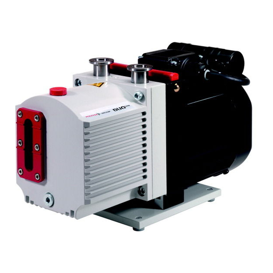
Product description 13 14 Fig. 2: Structure of the rotary vane pump 1 Handle stand 2 Mains switch Drain screw for operating fluid 3 Rubber connector Sight glass 4 Motor Filling screw for operating fluid 5 Base plate Connection for the operating fluid return 6 Motor flange Vacuum flange with protective cap 7 Intermediate flange (only with M version) - Page 19 Product description The rotary vane pump is an oil-sealed rotational displacement pump. The pumping system is made up of the housing, the eccentrically mounted rotor, and the centrifugally- and spring-loaded radially sliding vanes, which divide the suction chamber into multiple chambers. The volume of each chamber changes periodically as the rotor rotates.
-
Page 20: Transportation And Storage
► Take particular care and pay special attention when transporting products manually. ► Do not stack the products. ► Wear protective equipment, e.g. safety shoes. Pfeiffer Vacuum recommends keeping the transport packaging and original protective cov- General information regarding safe transport 1. Observe the weight specified on packaging. - Page 21 Transportation and Storage Procedure 1. Fill the vacuum pump with operating fluid up to the upper edge of the sight glass. 2. Close both connection flanges and all openings on the vacuum pump. 3. Make sure that the gas ballast valve is closed. 4.
-
Page 22: Installation
Property damage from contaminated gases Pumping down gases that contain impurities (condensate, particles) damages the vacuum pump. ► Use suitable filters or separators from the Pfeiffer Vacuum range of accessories, to protect the vacuum pump. Installation and operation of accessories Pfeiffer Vacuum offers a series of special, compatible accessories for its rotary vane pumps. -
Page 23: Connecting The Exhaust Side
6. Support or suspend the piping to the vacuum pump so that no piping system forces act on the vacuum pump. 7. Connect both flanges with a circlip. 8. Use a separator or filter from the Pfeiffer Vacuum line of accessories if necessary. -
Page 24: Establishing Mains Connection
Installation Fig. 7: Exhaust connection with flange connection 1 Exhaust line Centering ring with nozzle and O-rings 2 Protective cap Circlip Procedure 1. Remove the protective cap from the exhaust flange. 2. Observe the centering ring with nozzle including the corresponding O-rings (2×). 3. -
Page 25: Fig. 8: Motor Circuit Diagram, Single-Phase Motor With Switch
Installation NOTICE Property damage from the voltage range being set incorrectly Recommissioning after longer downtimes of the vacuum pump or after changing the oil requires the current settings to be checked. ► Before switching the vacuum pump on each time, check the currently set voltage range. ►... -
Page 26: Filling The Operating Fluid
Risk of damage due to the use of non-approved operating fluid Product-specific performance data are not achieved. All liability and warranty claims against Pfeiffer Vacuum are also excluded. ► Only use approved operating fluids. ► Only use other application-specific operating fluids after consultation with Pfeiffer Vacuum. 26/60... -
Page 27: Fig. 10: Filling The Operating Fluid
The type of operating fluid specified, as well as the filling quantity for the entire rotary vane vacuum pump, are shown on the rating plate. Only the operating fluid used during initial installation is permissi- ble. Subsequent change is possible only after consultation with Pfeiffer Vacuum. Approved operating fluids ●... -
Page 28: Operation
Operation 6 Operation 6.1 Putting the vacuum pump into operation WARNING Danger of poisoning due to toxic process media escaping from the exhaust pipe During operation with no exhaust line, the vacuum pump allows exhaust gases and vapors to escape freely into the air. There is a risk of injury and fatality due to poisoning in processes with toxic process media. -
Page 29: Operating The Rotary Vane Pump With Gas Ballast
Operation NOTICE Risk of damage to the drive from increased motor current consumption At an intake pressure of approximately 300 hPa and under unfavorable operating conditions (such as for example exhaust side counterpressure), the power input exceeds the rated current. ►... -
Page 30: Refilling Operating Fluid
Operation geöffnet/ open geschlossen/ closed Fig. 11: Gas ballast valve Behavior with process gases with condensable vapors ► Operate the vacuum pump with gas ballast, i.e. with the gas ballast valve open. Open gas ballast valve ► Rotate knob on the gas ballast valve to the left to open, into position “1”. Close gas ballast valve ►... -
Page 31: Switching Off The Vacuum Pump
► Shut off the intake line with an additional shut-off valve, after the vacuum pump is switched off during longer venting operations. Pfeiffer Vacuum rotary vane pumps have an integral vacuum safety valve on the intake side. The vac- uum safety valve automatically closes from a differential pressure of ≥250 hPa between the exhaust and intake sides, when the vacuum pump is switched off, and vents the vacuum pump. -
Page 32: Maintenance
► Dismantle the vacuum pump for inspection, away from the system if necessary. NOTICE Danger of property damage from improper maintenance Unprofessional work on the vacuum pump will lead to damage for which Pfeiffer Vacuum accepts no liability. ► We recommend taking advantage of our service training offering. -
Page 33: Checklist For Inspection And Maintenance
You can carry out maintenance work at Maintenance Level 1 yourself. We recommend Pfeiffer Vacuum Service for carrying out maintenance work of Maintenance Level 2 and Maintenance Level 3 (revision). If the required intervals listed below are exceeded, or if mainte- nance work is carried out improperly, no warranty or liability claims are accepted on the part of Pfeiffer Vacuum. -
Page 34: Changing The Operating Fluid
Should process conditions change, you can convert to a different operating fluid type. Safety data sheets You can obtain the safety data sheets for operating fluids from Pfeiffer Vacuum on request, or from the Pfeiffer Vacuum Download Center. -
Page 35: Determine The Degree Of Aging Of P3 Operating Fluid
You can determine the degree of aging of P3 operating fluid in clean processes using the color chart (in accordance with DIN 51578). The supplementary sheet with the document number PK0219 can be ob- tained from the Pfeiffer Vacuum Download Center. Prerequisites ●... -
Page 36: Fig. 13: Draining The Operating Fluid
► Wear protective equipment. ► Use a suitable collection vessel. Cleaning by changing the operating fluid Pfeiffer Vacuum recommends, in cases of heavy contamination with process residues, cleaning the inside of the vacuum pump with several operating fluid changes. Prerequisites ●... -
Page 37: Rinsing And Cleaning The Rotary Vane Vacuum Pump
– Tightening torque: 0.3 Nm 7.4.3 Rinsing and cleaning the rotary vane vacuum pump Cleaning by changing the operating fluid Pfeiffer Vacuum recommends, in cases of heavy contamination with process residues, cleaning the inside of the vacuum pump with several operating fluid changes. Prerequisites ●... -
Page 38: Cleaning The Gas Ballast Valve
Maintenance Fig. 14: Remove/fit rotary vane vacuum pump cap 1 Allen head screw (2×) Pumping system 2 Cap Stand 3 O-ring Remove the cap 1. Drain the operating fluid. 2. Unscrew both Allen head screws from the cap. 3. Remove the cap from the stand in axial direction. –... -
Page 39: Fig. 15: Gas Ballast Valve
Maintenance ballig/ convex Fig. 15: Gas ballast valve 1 O-ring Compression spring 2 Screw cap Washer 3 Valve flap Circlip 4 Valve housing Cam plate 5 O-ring Countersink screw (2×) 6 Tappet Head 7 Cylinder bolt Countersink screw Required tools ●... -
Page 40: Changing The Operating Fluid Type
Maintenance 12. Install the complete valve with O-ring in the vacuum pump. 13. Tighten the countersunk head screws (2x). – Tightening torque: 1.0 Nm. 7.6 Changing the operating fluid type Possibilities for changing the operating fluid type The operating fluid type can be changed between mineral operating fluid – P3 – and syn- thetic operating fluid –... -
Page 41: Decommissioning
10. Pack the vacuum pump together with a drying agent in a plastic bag, and seal the vacuum pump airtight if it is to be stored in rooms with damp or aggressive atmospheres. 11. For longer storage periods (> 2 years), Pfeiffer Vacuum recommends changing the operating fluid again prior to recommissioning. -
Page 42: Malfunctions
► Dismantle the vacuum pump for inspection, away from the system if necessary. NOTICE Danger of property damage from improper maintenance Unprofessional work on the vacuum pump will lead to damage for which Pfeiffer Vacuum accepts no liability. ► We recommend taking advantage of our service training offering. -
Page 43: Tbl. 7: Troubleshooting For Rotary Vane Pumps
● Top up the operating fluid. ● Leak in system ● Locate and eliminate the leak. ● Vacuum pump is dam- ● Contact Pfeiffer Vacuum Service. aged Pumping speed of vacuum ● The intake line is not suit- ● Make sure that connections are... -
Page 44: Service Solutions From Pfeiffer Vacuum
We are consistently striving to perfect our core competence, service for vacuum components. And our service is far from over once you’ve purchased a product from Pfeiffer Vacuum. It often enough really just begins then. In proven Pfeiffer Vacuum quality, of course. - Page 45 Service solutions from Pfeiffer Vacuum 5. Prepare the product for transport in accordance with the details in the declaration of contamination. a) Neutralize the product with nitrogen or dry air. b) Close all openings with airtight blank flanges. c) Seal the product in appropriate protective film.
-
Page 46: Spare Parts
Spare parts 11 Spare parts 11.1 Ordering spare parts packs Procedure 1. Have the vacuum pump part number to hand, along with other details from the rating plate. 2. Install original spare parts only. Spare parts pack Pump version Order no. Maintenance kit 1 – maintenance level 1 Standard, M version PK E01 050 CT Radial shaft seal ring set –... -
Page 47: Set Of Vanes
Spare parts 11.6 Set of vanes The set of vanes contains: ● Vane ● Vane springs 11.7 Coupling set for versions with magnetic coupling The coupling set contains: ● Both coupling halves ● Containment shell with O-ring 47/60... -
Page 48: Accessories
Accessories 12 Accessories View the range of accessories for Pfeiffer Vacuum rotary vane pumps online at pfeiffer-vac- uum.com. 12.1 Accessory information Condensate separator Protects the pump from liquids from inlet line or backlow from exhaust line Oil mist filter Prevents emission of oil mist... -
Page 49: Tbl. 10: Consumables
Accessories Description Order no. P3, mineral oil, 0.5 l PK 001 136 -T P3, mineral oil, 1 l PK 001 106 -T Tbl. 10: Consumables 49/60... -
Page 50: Technical Data And Dimensions
Technical data and dimensions 13 Technical data and dimensions 13.1 General Basis for the technical data of Pfeiffer Vacuum rotary vane pumps: ● Specifications according to PNEUROP committee PN5 ● ISO 21360-1: 2016: “Vacuum technology - Standard methods for measuring vacuum-pump per- formance - Part 1: General description”... -
Page 51: Technical Data
Technical data and dimensions 13.3 Technical data Classification Duo 1.6 Duo 1.6 Duo 1.6 Duo 1.6 Duo 1.6 Order number PK D56 702 PK D56 707 PK D56 710 PK D56 711 PK D56 712 Flange (in) DN 16 ISO-KF DN 16 ISO-KF... - Page 52 0.4 l Weight 9.6 kg 9.6 kg 10.8 kg 10.8 kg 9.6 kg Tbl. 14: Technical data, Duo 1.6 Classification Duo 1.6 M Duo 1.6 M Duo 1.6 M Order number PK D56 102 PK D56 107 PK D56 112...
-
Page 53: Dimensions
11 kg Tbl. 15: Technical data, Duo 1.6 M 13.4 Dimensions Dimensions in mm 13.4.1 Standard version 334.5 28.5 2× DN 16 ISO-KF 122.7 32.5 85.2 ± Fig. 16: Dimensions Duo 1.6, 100 V, 50 Hz with switch, 95–105 V, 60 Hz 53/60... -
Page 54: Fig. 17: Dimensions Duo 1.6, Single-Phase Motor, 105 V, 50 Hz | 115-125 V, 60 Hz
28.5 2× DN 16 ISO-KF 122.7 32.5 85.2 ± Fig. 17: Dimensions Duo 1.6, single-phase motor, 105 V, 50 Hz | 115‑125 V, 60 Hz 2× DN 16 ISO-KF 122.7 32.5 85.2 ± Fig. 18: Dimensions Duo 1.6, single-phase motor, 100/200 V, 50/60 Hz... -
Page 55: Fig. 19: Dimensions Duo 1.6, Single-Phase Motor, 115/230 V, 50/60 Hz
Technical data and dimensions 2× DN 16 ISO-KF 122.7 32.5 85.2 ± Fig. 19: Dimensions Duo 1.6, single-phase motor, 115/230 V, 50/60 Hz 28.5 2x DN 16 ISO-KF 122,7 32.5 85.2 ± Fig. 20: Dimensions Duo 1.6, single-phase motor, 230‑240 V, 50/60 Hz... -
Page 56: Version
Dimensions Duo 1.6 M, 100 V, 50 Hz with switch, 95‑105 V, 60 Hz 28.5 2× DN 16 ISO-KF 122.7 86.2 33.5 ± Fig. 22: Dimensions Duo 1.6 M, single-phase motor, 105 V, 50 Hz | 115‑125 V, 60 Hz 56/60... - Page 57 Technical data and dimensions 28.5 2× DN 16 ISO-KF 122.7 (7.2) 33.5 86.2 ± Fig. 23: Dimensions Duo 1.6 M, single-phase motor, 230‑240 V, 50/60 Hz 57/60...
-
Page 58: Declaration Of Conformity
● Restriction of the use of certain hazardous substances, delegated directive 2015/863/EU The authorized representative for the compilation of technical documents is Mr. Sebas- tian Oberbeck, Pfeiffer Vacuum GmbH, Berliner Strasse 43, 35614 Asslar, Germany. Rotary vane pump Duo 1.6 Duo 1.6 M... - Page 59 59/60...
Need help?
Do you have a question about the DUO 1.6 and is the answer not in the manual?
Questions and answers