Table of Contents
Advertisement
Quick Links
Advertisement
Table of Contents

Related Manuals for Woodway Opti-Link


Summary of Contents for Woodway Opti-Link
- Page 1 Opti-Link ENGINEERS FOR THE EMERGENCY WARNING INDUSTRY...
- Page 2 Installation and Operation Disclaimer This document is intended to be used as a reference guide for the installation and operation of the Opti-Link Control System. Every effort has been made to ensure the reliability and accuracy of the information contained in this manual at the time of going to press.
-
Page 3: Table Of Contents
............................... 5 XTERNAL NPUT CHANGING AND FITTING THE SWITCH LEGENDS ....................6 : ............................6 O FIT THE SWITCH LEGENDS TROUBLESHOOTING ............................... 7 OPTI-LINK SYSTEM INSTALLATION WIRING DIAGRAMS ..................8 ................................8 YSTEM IRING ................................9 UXILIARY ELAYS – H .................... -
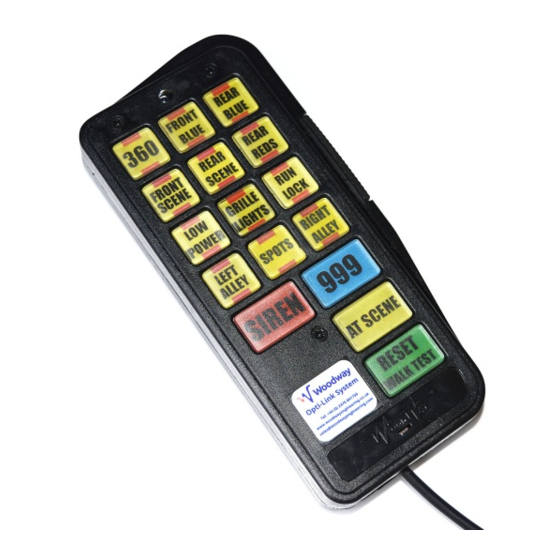
Page 4: The Opti-Link Control System
We strongly recommend that with the exception of low current switching Woodway light bars all devices to be controlled are connected via relays as shown on page 9 of the installation information. -
Page 5: System Operation
PA Microphone The Keypad incorporates a public address microphone for use with a Woodway siren with PA capability and is made active via a PTT (Press-To-Talk) switch located on the side of the keypad. When the switch is operated it will mute any active siren tones. -
Page 6: Keypad Programming
The special strobe setting is only applicable to switches 1 to 3 and is usually set when the system is used to control ‘360’ light selection on a Woodway lightbar. When this option is set pressing SW1 will also activate SW2 and SW3. -
Page 7: Changing And Fitting The Switch Legends
Re-fit all the screws. Do not over tighten the screws as this may distort the plastics and prevent the correct action of the switches Check that all the buttons are free and operate reliably before reconnecting the switch panel. Woodway Engineering Ltd OPTINS-4.0 Rev 4 Page 6 of 9... -
Page 8: Troubleshooting
When selecting ‘360’ the lightbar is Switches are incorrectly set. For the ‘360’ to function correctly when not functioning connected to a Woodway lightbar only SW1 can be used as 360 and the ‘Special Strobe Function’ must be set. (See Keypad Programming on Page 5) Switch panel cannot be programmed. -
Page 9: Opti-Link System Installation Wiring Diagrams
Opti-Link WOODWAY Installation and Operation Opti-Link System Installation Wiring Diagrams System Wiring Woodway Engineering Ltd OPTINS-4.0 Rev 4 Page 8 of 9 December 2007... -
Page 10: Auxiliary Relays
Figure 5 Wire Colour Function Red/White Not Used White/Green Horn Ring White/Brown Wail White/Red Yelp White/Orange Hands Free White/Yellow Not Used White/Violet White/Black Mic - White/Blue Mic + Woodway Engineering Ltd OPTINS-4.0 Rev 4 Page 9 of 9 December 2007...
Need help?
Do you have a question about the Opti-Link and is the answer not in the manual?
Questions and answers