Advertisement
Table of Contents
- 1 Warranty
- 2 General Informations
- 3 Safety Rules
- 4 Appliance Description
- 5 Technical Data
- 6 Electrical Scheme
- 7 Control Panel
- 8 Receipt of Product
- 9 Floor Standing
- 10 Power Connections
- 11 Gas Connection
- 12 Preliminary Operations
- 13 Gas Transformation
- 14 Ordinary Maintenance
- 15 Components Replacement
- 16 Useful Information
- Download this manual
Advertisement
Table of Contents

Related Manuals for Italkero Stratos 3.0 aluminum


Summary of Contents for Italkero Stratos 3.0 aluminum
- Page 1 Norway...
- Page 2 COMPLIANCE O u r a p p l i a n c e s a r e c o m p l i a n c e a t : G a s d i r e c t i v e 2 0 0 9 / 1 4 2 / C E ( e x . 9 0 / 3 9 6 / C E E ) E l e c t r o m a g n e t i c d i r e c t i v e c o m p a t i b l e 2 0 0 4 / 1 0 8 / C E 0694 L o w - t e n s i o n d i r e c t i v e 2 0 0 6 / 9 5 / C E...
-
Page 3: Warranty
Dear Customer We inform you that this unit has a warranty specification (see specifications in the text to follow). During the first switch on, there may be vapor emissions, or bothersome odors absolutely not dan- gerous. In these cases, you should do operate the device at the maximum power for several hours, keeping the room well ventilated. - Page 4 INDEX GENERAL General informations pag.5 Safety rules pag.5 Appliance description pag.6 Identification pag.6 Structure pag.7 Technical data pag.8 Accessories pag.8 Electrical scheme pag.9 Control panel pag.10 INSTALLATION Receiving the product pag.11 Weight and dimension pag.13 Installation: WALL FITTING or FLOOR STANDING - Apparatus choice location pag.14 - Intake &...
-
Page 5: General Informations
GENERAL INFORMATIONS After removing the packaging, check the integrity of The appliance should be serviced at least once a the contents. In case of discrepancies, contact the year. Agency that sold the appliance. This booklet is an integral part of the appliance and The appliance must be installed by an authorised must therefore be carefully looked after and company pursuant to Law no. -
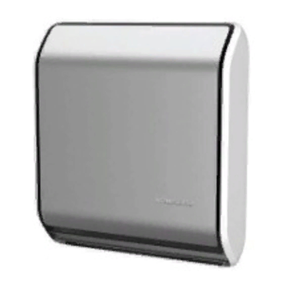
Page 6: Appliance Description
APPLIANCE DESCRIPTION The appliance is a gas radiator that heat up the Note: At request the apparatus can be furnished atmosphere. already arranged at GPL. It has an intake of air that goes in the combustion chamber type C. It also has an electrical device that allows you to do a series of things. - Page 7 STRUCTURE High Safety thermostat Tangential fan Control unit Power plug Technical plate Gas Valve Gas valve Protection fuse Centrifugal fan Low Safety thermostat Burner unit Condenser Detection Electrode (mod. 5.0, 7.0 and 9.0) Digital Wireless control (optional) Ignition Electrodes Main switch Heat exchanger "Integrated"...
-
Page 8: Technical Data
TECHNICAL DATA MODEL G30/G31 G30/G31 G30/G31 G30/G31 Terminal capacity nomination (qn) (Hi) 2,50 4,70 6,80 8,60 Terminal capacity reduction (qn) (Hi) 2,32 4,34 6,25 7,74 7,20 Terminal power convector nomination (pn) (Hi) 1,70 3,30 4,80 5,70 Terminal power convector reduction (pn) (Hi) 1,58 3,05 4,41... -
Page 9: Electrical Scheme
ELECTRICAL SCHEME 1 2 3 4 5 6 V.T. V.T. F 1AT 250V 230V~ SPLIT ROOM PROBE DETECTION ELECTRODE COMBUSTION FAN ELECTRIC GAS VALVE TANGENTIAL FAN FUSE CN... CONNECTOR LINE CONNECTOR POWER TERMINAL ELECTRIC GAS VALVE IGNITION TRANSFORMER PHASE LINE BLUE WIRE NEUTRAL LINE WHITE WIRE... -
Page 10: Control Panel
CONTROL PANEL - GREEN Led On = heater On - GREEN Led Off = heater Off - RED Led On = burner flame block - RED Led Off = heater released - RED Led SLOW flashing = pressure switch donʼt switch ON - RED Led FAST flashing = locked pressure switch - Thermostat knob regulation (approximate value): from MIN 5°C to MAX 35°C A = from 5°C to 10°C (rotate the trimmer all to the right) -
Page 11: Receipt Of Product
RECEIPT OF PRODUCT The appliance is supplied in one cardboard package: Contents of appliance package: Appliance Manual control Metal template Pipe KIT: 1 Adapter union 1 Suction pipe (L = 500mm) (Ø 32mm Mod. 3.0 - 5.0) (Ø 54mm Mod. 7.0 - 9.0) 1 exhaust pipe (L = 500mm) (Ø... - Page 12 SPLIT PIPE KIT WITH SINGLE PIPE END PIECE (SPECIAL) - Ø 32 pipe kit with single pipe end piece (TP32SP 00000) Contents of kit package: Description Paper template for appliance positioning Anchors Ø 8 mm (for fastening the template on the wall) Adapter connection for Ø...
- Page 13 Verify Tube kit When the Appliance is being installed be sure that all the tubes are adjusted for the installation you want done. The tube kits available are: MODEL Description CODE T P 3 2 S P 0 0 0 0 0 KIT special EXHAUST &...
- Page 14 INSTALLATION: WALL FITTING or FLOOR STANDING GENErAL INformATIoNS This apparatus is tin respect to the environment; the air is intake from the outside. -When the appliance is being installed do not use other pieces that are not give from the manufacturer. -Don’t let the electrical cable touch heated parts, like the grill or the intake &...
- Page 15 Installation stage The appliance installations stages are: - Apparatus choice location - Tube installation - Parallel tube kit Ø 32 mm or Ø 54 mm with unique terminal (standard) - Separated pip kit Ø 32 mm o Ø 54 mm with single terminal (special) - Appliance installation - Electrical collegaments...
- Page 16 FITTING THE TEMPLATE, UNION AND PIPES To determine the position of the APPLIANCE and of the support template (3), use the paper template (4) provided: - level and mark the holes (1, 2), then remove the paper template from the wall; - make the holes (2) for fastening the template to the wall;...
- Page 17 outside grill assemblage GP and GPu Ø32 To assemble the grill you only need the inserts, and the steeliness steel flange. Ø54 Assemblage SDP protection Ø32 The assembling is execute in the following way: -After you have drilled on the outside wall put the protection (1) with mortar Ø54 -Assemblage the terminal tube with the equipment...
- Page 18 How to mount special pipes kit from inside the room to be warmed. Drill the hole on the wall. Shorten the special pipes in order to match the real thickness of the wall (see picture). IMPORTANT: Cutting must be perpendicular to the pipe axis, please handle with care in order not to deform the pipes.
- Page 19 Chances A1/A2 tube assemblage in wall. This solution can be adapted when the wall thick- Before you wall up the tubes, only for lengths ness consent to execute the trace for the connection greater than 50cm, provide to insulate the tubes, and can be realize in two ways: exhaust fume tubes, with strong materials resistant at a greater temperature of 200 °C (ex.
- Page 20 Group adapter connection tube The group adapter preparation is effected by two kinds of tubes Ø 32/54 mm -- With Ø 32 mm tubes. - Adapt the length tube; to the wall space so it increases 25 mm, then cut it. - Assemble the tube (1) cute at right measure, and the curve (2) for the adapter connection (3) then fasten with the furnished screws.
- Page 21 Chance A2 with Ø 32/ 54 mm tubes To install the fume exhaust and air suction pipes: - level, mark and make the hole for the pipes (1) and the holes (2) for fastening the template (3). - remove the plate (5) and fit the unit (6) on the tem- plate;...
- Page 22 Chance B – inside tube assemblage This system is used when the wall does not permit to realize the proper work to install the tubes. To install the tubes you need the spacing bar (1). M I N 2 0 0 Before you start the work check that there is enough space that permits the appliance to do the right function.
- Page 23 Chimneypot assemblage To assemble the chimneypot on the exhaust intake tubes use the clamp (1) and the (2) safety screw. The chimneypot application has to satisfy the fol- lowing requirement. -The top of the exhaust fume tube has to be out of the ebb zone, to avoid the eventual pressures that will prevent the free exhaust product of the combu- stion in the atmosphere.
- Page 24 FITTING THE REMOTE DIGITAL CONTROL For correct installation of the remote control in the required position, follow these instructions: - Choose the position of the remote control: - away from the appliance; - on the BASE (provided). - Install the remote control. To ensure correct operation, install the remo- te control at a MAX distance of 6 metres.
-
Page 25: Floor Standing
FLOOR STANDING mouNTING THE “fLoor STANDING” SuPPorT STruCTurE ImPorTANT! read and respect the general information of INSTALLATIoN chap. The support structure kit is used when the wall selec- ted for installation is unable to support the weight of the appliance. Thanks to this accessory, all the wei- ght of the appliance is discharged onto the floor. - Page 26 PROTECTION FOR WALLS MADE OF WOOD PANELS fITTING SILumINA frAmE ASSEmBLY for INSTALLATIoN oN ComBuSTIBLE or WooDEN WALL This assembly is suitable for walls between 100 mm 2) Fit the external stainless - stell (3) AISI 304 to the and 500 mm thick. outside of the wall using the 4 screws, included in the pack, if the external wall is hard stone chose - Having chosen the position for the heater in accor-...
-
Page 27: Power Connections
POWER CONNECTIONS The appliance must be installed by companies approved pursuant to Law no. 46 dated 5 March 1990. Upon completing the installation, such compa- nies must issue a declaration of installation confor- mity in accordance with applicable national and local laws (see art. -
Page 28: Preliminary Operations
PRELIMINARY OPERATIONS The appliance is furnished and preset for the gas Only fill the tray with water. Avoid all other liquids that could damage the tray or cause function (G 20) and regulated in factory. appliance malfunctions. Note: the apparatus can also be requested with the GPL gas function. - Page 29 PROCESSOR CONTROL BOX (P.C.B ASSY) MALFUNCTION In case of any malfunctions in the control unit, RESET as follows: a - press the On/Off button as shown in the illustra- tion. b - connect and disconnect the plug from the socket or move the master switch to “off”...
-
Page 30: Gas Transformation
GAS TRANSFORMATION The appliance is preset for the methane gas (G20) following the technical label, but you can change at GPL (G30/G31) with the transformation that is furnished. The transformation has to be done only by Technical Service Assistance, the manufacturer or by authori- zed persons even if appliance has been already installed. - Page 31 REGOLATION The appliance is furnished with (G20) gas function following the Technical label, and the constructor already regulates it. If you make a new regulation, like exchanging the gas valve, or a gas transforma- tion from Methane to GPL or reversed, this regula- tion has to be done from a Technical service Assistance or by the manufacture Gas methane G 20(20mbr);...
-
Page 32: Ordinary Maintenance
Whenever the apparatus is going to be regulated at the modulator body (4). pure Propane, to avoid heat exchanger overheating, Rotating the regulator screw (3) clockwise the pres- is necessary knowing that you are using the proper sure decrease, rotating counter clockwise the pres- gas, but if you use a un proper gas like a mixture of sure increases. -
Page 33: Components Replacement
Cleaning Electrode The ignition electrode (1) and revelation (2) have to be cleaned very carefully, after a period of time they get fragile because of the work they have to perform. - Unscrew the screws (3 o 4) and extract the electro- de group (1 o 2) using a little brush with metallic hair for cleaning, after insert the electrode group (1 o 2) if necessary exchange the seal gasket (5) be real... - Page 34 Replacing the room probe Follow the instructions below to remove and refit the probe: - disconnect the connector of the probe cable (1) from the control unit (2); - take out the damaged probe; - replace the component part and fit it back, perfor- ming removal operations in the opposite sequence.
- Page 35 Electrodes replacement Follow the indication to replace the electrode. - The ignition electrode (1) and revelation (2) half to be cleaned real carefully, after a period of time they get fragile because of the work they which they do. - Take off the high-tension cable - Unscrew the screws (3 o 4) and extract the electro- de group (1 o 2) - Reassemble the electrode (1 o 2) with the reversed...
- Page 36 Replacing the gas valve Follow the instructions below to remove and refit the valve: - remove the power connections. - loosen the retention nut that secures the burner pipe (1) to the valve body (2). - loosen the retention nut that secures the mains gas pipe (3) to the valve body.
- Page 37 DISASSEMBLY & RIASSEMBLY OF THE CASING Disassembly cover - Disassembly the casing; - Remove the cup (3); - Unscrew the screw (2); - Remove the outside skirt (1) completely; - To replace the skirt do the reversed sequence. EVENTUAL ANOMALY FAULT CAUSE REMEDY...
- Page 38 FAULT CAUSE REMEDY The thermostat does not engage. Thermostat programming wrong Adjust thermostat: - increase - decrease. Unfavourable appliance position. Change appliance position PROBE offset faulty. Offset correctly Upper or lower grille blocked Clean / Free SPLIT probe has come out of seat. Position correctly INTEGRATED room probe faulty Replace Probe or Wireless...
-
Page 39: Useful Information
USEFUL INFORMATION Seller Street tel. Installer Street tel. Technical Service Assistance Street tel. Date Intervention CUSTOMER SERVICE...
Need help?
Do you have a question about the Stratos 3.0 aluminum and is the answer not in the manual?
Questions and answers