
Summary of Contents for Ligao JLM-S
- Page 1 Instruction Manual JLM-S Solenoid Metering Pump Carefully read and understand all precautions before installing and servicing.
-
Page 3: Table Of Contents
CONTENT 1 Precautions..................... 1 2 Product Introduction................3 2.1 Overview..................3 2.2 Technical Parameter..............4 2.2.1 General Parameter............4 2.2.2 Performance Parameter..........5 2.2.3 Installation Drawing............5 2.3 Operation Instruction..............6 2.4 Unpacking Check List................ 7 3 Installation....................8 3.1 Pump Installation................ 9 3.2 Tubing Connections..............14 3.3 Food Valve and Suction Tubing Installation......14 3.4 Injection Valve and Discharge Tubing Installation.... -
Page 4: Precautions
1 Precautions The following precautions should be taken when operating metering pumps. Please read all sections carefully prior to installation. Protective Clothing Wear protective clothing, face shield, safety glasses and gloves when operate or near your metering pump. Additional precautions should be taken depending on the pumped solution. - Page 5 damage. If tubing is exposed to sunlight, black UV resistant tubing should be installed. Check tubing frequently for cracks and replace as necessary. Plumbing Code Please adhere to your local plumbing codes and requirements. Be sure installation does not constitute a cross connection.
-
Page 6: Product Introduction
2 Product Introduction 2.1 Overview JLM-S metering pump is a microprocessor controlled solenoid diaphragm pump with changeable frequency. It is capable for all kinds of solutions dosing, including corrosive solutions. It is widely used in petroleum, chemical, food,... -
Page 7: Technical Parameter
JLM-S solenoid metering pump rated flow range is 1 ~ 20 l / h, with corresponding maximum output pressure of 10 ~ 1bar. The pump outlet displacement can be adjusted according to the pulse frequency selection switch. -
Page 8: Performance Parameter
Protection Class; IP65 Insulation Degree: Outer Connection Control: Passive Contact Pulse Signal Contact Load:5V,0.5mA 2.2.2 Performance Parameter Flow Pressure Frequency Caliber Model Stroke/min JLM-S0110 ¢5 JLM-S0408 ¢5 JLM-S0607 ¢5 JLM-S0805 ¢5 JLM-S1204 ¢5 JLM-S1502 ¢5 JLM-S2001 ¢5 2.2.3 Installation Drawing... -
Page 9: Operation Instruction
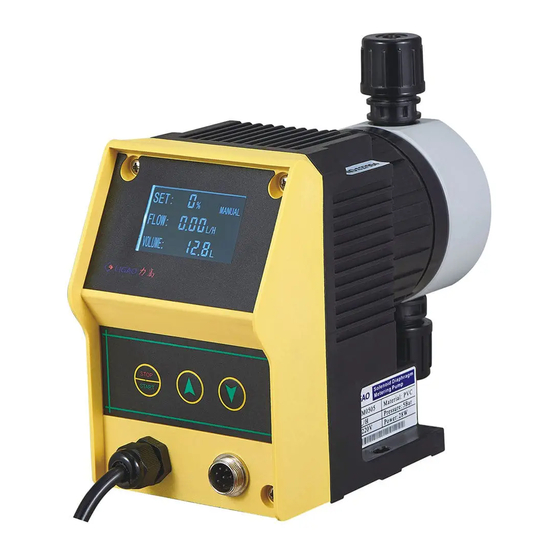
2.3 Operation Instruction 1 Display Screen 2 Stop/Start Button 3 Increase Button 4 Decrease Button 5 Power Cable 6 Signal Plug SET: MANUAL 12.88 FLOW: AUTO REMOTE 1999.9 Stop State Running State Setting State... -
Page 10: Unpacking Check List
2.4 Unpacking Check List Your carton will contain all or some of the following items. Please notify the carrier immediately if there are any signs of damage to the pump or its parts. -
Page 11: Installation
3 Installation Due to the possibility of water residue at the factory test, if the metered solution can not be in contact with water, water must be removed before starting use and the inside of the pump head can be flushed through the suction side with suitable solution. -
Page 12: Pump Installation
limit the maximum back pressure within the allowable value. Only use the hose diameter corresponding to the hose, hose connector and the provisions of the specifications of the hose, or can not guarantee the connection of a solid and lasting. Do not reduce the hose specifications. Longer pipelines or medium viscous use larger cross-section pipelines and pulsating dampers. - Page 13 This type of installation does not require a bottom valve. If it is transported downwards or transported to a low or low pressure place, install a back pressure valve or an anti-siphon valve. All solutions can be used in this type of immersion, but this is especially recommended for high concentrations of liquids.
- Page 14 Note: The following figure is typical wrong installation.
- Page 15 B. Suction Lift; Tank Mount: The pump is mounted on the top of the solution tank.
- Page 16 Wall Bracket Mount:The pump is mounted on the wall with bracket above the solution tank. This method allows for easy changing of the solution tanks.
-
Page 17: Tubing Connections
3.2 Tubing Connections Insert tubing through coupling nut and clamp. Cut the hose at suitable length, and insert the nozzle as deep as possible. Enlarge the diameter of the hose if needed. Press the clamp and tighten the coupling nut. 3.3 Food Valve and Suction Tubing Installation The bottom valve acts as a check valve, allowing the pump to self-priming in the case of a suction installation. -
Page 18: Injection Valve And Discharge Tubing Installation
(see section 3.2). Slide the ceramic weight over the tubing end until it contacts the top of the foot valve coupling nut. Place foot valve and suction tubing into the solution tank. Check if the foot valve is vertical and approximately 50mm from the bottom of the tank. -
Page 19: Air Release Valve Installation
3.5 Air Release Valve Installation Air release valve with exhaust sampling function. The valve is mounted on the outlet check valve and is connected to the hose to allow the medium to return to the dosing tank. In order to ensure smooth self-absorption, the tube can not be immersed in the medium. -
Page 20: Operation And Setting
4 Operation and Setting 4.1 Start-Up and Priming Please read the following carefully before proceeding to the next step. After all the protective measures are done, the pump is installed, the pipe is firmly connected, open all the control valves on the inlet and outlet lines, you can start priming the pump head. -
Page 21: Setting
discharge check valve( see check valve assembly), and re-start the prime steps. 4.2 Setting 1.Stop State: (Screen display “0 ”) ; Press "STOP / START" button to run the pump. In running state, press "STOP/ START" button to stop the pump. - Page 22 3. Parameter List: Code Name Scope Description Machine Code 1-254 ID code for pump Strokes/Minute 10-180 Pump working frequency Flow Setting 0-999 Setting the flow rate Percentage 0-100 Percentage of the flow 0:OFF RS485 control 1:ON 0:Manual control 1:Pulse signal multiply Control mode 2:Pulse signal division 3:4-20mA signal...
- Page 23 pressing the button , range from 10-180. STPO START 2. Set the calibrated flow value. This value is 10 times of measurement flow value. For example, if the the calibrated flow is 6.0 l/h, input value 60. Press STPO START button to adjust the value from 0-999.
- Page 24 6. Base of pulse counts , range 0-255. This setting only works under Pulse Signal Multiply and Pulse Signal Division mode. Under Pulse Signal Multiply mode, the pump will make strokes of this value receiving each pulse signal. Under Pulse Signal Multiply model, the pump will make one stroke after receiving the pulse signals of this value.
- Page 25 Register Address Storage Data Scope Area 2106 0x083A Switch Status HI 0 OFF 1 ON 2107 0x083B Switch Status LO 2108 0x083C Pulse per Minute HI 0x000a-0x00b4 2109 0x083D Pulse per Minute LO 2110 0x083E Pulse Base HI 0x00-0x00ff 2111 0x083F Pulse Base LO 2112...
- Page 26 2124 0x084C Instant Flow HI 0x0000-0x03e7 2125 0x084D Instant Flow LO 2126 0x084E Remote Control HI 0x0000 OFF 0x084F Remote Control LO 2127 0x0001 ON 2129 0x0851 Switch Status HI 0x0000 OFF 0x0001 ON 2130 0x0852 Switch Status LO 2131 0x0853 Pulse per Minute HI 0x000a-0x00b4...
- Page 27 Host send format: Machine Function Register First Number of CRC Check Code Code Address Registers 1-254 0x04 0x083A 0x0009 0x**** (1 Byte) (1 Byte) (2 Byte) (2 Byte) (2 Byte) Slave return correctly: Machine Function Register Number of CRC Check Code Code First...
- Page 28 Slave return correctly: Machine Function Bytes Register Value Code Code Check 1-254 0x04 0x02 Cumulative Flow 0x**** (1 Byte) (1 Byte) (1 Byte) HI,Cumulative Flow LO (2 Byte) (0x02 Byte) Slave error returned: Machine Function Error Code Code Code Check 1-254 0x84 0x01 (Check does not pass)...
- Page 29 Slave error returned: Machine Function Error Code Code Code Check 0-254 0x86 0x01(Check does not pass)or 0x03 0x**** (1 Byte) (1 Byte) (Remote control OFF) (2 Byte) (1 Byte) Function 3: Write multiple register functions (0x10) Host send format: Machin Functio Register Number...
-
Page 30: Signal Connector Description
4.3 Signal Connector Description The signal plug has 7 lines,. The following is the wire color and the corresponding function. 1、 Blue——485 B 2、 Yellow——485 A 3、 Black/Green——Zero Line 4、 White——Pulse Input 5、 Grey—— Remote Control Switch 6、 Red——4-20mA Input Calibration Once the installation is complete, the approximate output of the pump is determined and the pump is... - Page 31 Using a stopwatch or timer, turn the pump on for a measured amount of time(120 strokes minimum). The longer the time period, the more confident you can be of the results. Stop the pump. Record the time and the volume of the discharge medium, calculate the flow rate.
-
Page 32: Maintenance And Repair
Maintenance and Repair Caution Electrical maintenance must be carried out by qualified electricians. Before servicing, unplug the power plug or disconnect the power. Cut off its power if there is a relay. Make sure that the pump's power supply is not turned on during maintenance. -
Page 33: Diaphragm Replacement
Material Safety Data Sheet provided by the material supplier. JLM-S metering pump is designed for trouble free operation, but in order to make the pump in the best working condition, the elastic parts must be maintained daily. - Page 34 Depressurize, drain, and remove the discharge tubing from pump . Place the bottom valve in water or other neutral solution. Start the pump and rinse the pump head. When the pump head is rinsed, remove the bottom valve from the liquid and continue running the pump to allow the air to enter until the pump head has no water or a neutral solution.
- Page 35 bolts①. Pull the pump head② and the bolts ① from the pump body. Turning the diaphragm③ counter-clockwise, and remove it. Turning a new diaphragm③ on to the driving shaft. Check the screw condition. Turning out the diaphragm③ again. ...
-
Page 36: Check Valves Replacement
5.3 Check Valves Replacement The check valve is a cartridge design and should be replaced as a whole component. Refer to the pump head section 7 in this manual. Depressurize and disconnect the discharge line from the pump head. ... -
Page 37: Troubleshooting
Re-install the check valve components (reverse position of disassembly). Reconnect to the pump head and the piping system. Troubleshooting Problem Possible Cause Solution Power supply fault. Check the power. Fuse blown. Eliminate overload, replace the fuse. Find the location of the circuit and Power circuit. - Page 38 Air in the pump cavity. Release the air. Increase suction pressure, Cavitation reduce the suction lift. Priming problem. Repriming and check the leakage. Strainer block. Clean or change the strainer. Check valves wear or Clean or change the check valves. with particles.
-
Page 39: Main Parts List
Main Parts List Pump Body... - Page 40 Pump Head...
- Page 41 Valves...
-
Page 42: Appendix
Power supply in some areas is unstable. Excessive fluctuations in power supply affect the use of equipment, and even cause damage to the pump. JLM-S solenoid metering pump power supply range is ± 10% of the rated voltage(for details, please refer to the relevant technical information). - Page 44 Zhejiang Ligao Pump Technology Co.,LTD ADD:No.227 Huishu Road,Linhai, Zhejiang, China TEL:0086-576-85289780 FAX:0086-576-85668297 WEBSITE: www.ligaopumps.com E-MAIL:sale2@ligaopumps.com Version: 3.0 Specifications subject to change without notice.
Need help?
Do you have a question about the JLM-S and is the answer not in the manual?
Questions and answers