Table of Contents
Advertisement
Advertisement
Table of Contents

Related Manuals for Asus P5S800-VM


Summary of Contents for Asus P5S800-VM
- Page 1 P5S800-VM...
- Page 2 E 2 4 1 9 E 2 4 1 9 E 2 4 1 9 E 2 4 1 9 E 2 4 1 9 Revised Edition V4 Revised Edition V4 Revised Edition V4 Revised Edition V4 Revised Edition V4 January 2006 January 2006 January 2006...
-
Page 3: Table Of Contents
Contents Notices ... vi Safety information ... vii About this guide ... viii Typography ... ix P5S800-VM specifications summary ... x Chapter 1: Product introduction Chapter 1: Product introduction Chapter 1: Product introduction Chapter 1: Product introduction Chapter 1: Product introduction Welcome! ... - Page 4 Contents Chapter 2: BIOS setup Chapter 2: BIOS setup Chapter 2: BIOS setup Chapter 2: BIOS setup Chapter 2: BIOS setup Managing and updating your BIOS ... 2-2 2.1.1 Creating a bootable floppy disk ... 2-2 2.1.2 ASUS EZ Flash utility ... 2-3 2.1.3 AFUDOS utility ...
- Page 5 Contents 2.5.3 ACPI APIC Support ... 2-25 2.5.4 APM Configuration ... 2-26 2.5.5 Hardware Monitor ... 2-27 Boot menu ... 2-29 2.6.1 Boot Device Priority ... 2-29 2.6.2 Disk Drives ... 2-29 2.6.3 Boot Settings Configuration ... 2-30 2.6.4 Security ... 2-31 Exit menu ...
-
Page 6: Notices
Notices Federal Communications Commission Statement Federal Communications Commission Statement Federal Communications Commission Statement Federal Communications Commission Statement Federal Communications Commission Statement This device complies with Part 15 of the FCC Rules. Operation is subject to the following two conditions: • This device may not cause harmful interference, and •... -
Page 7: Safety Information
Safety information Electrical safety Electrical safety Electrical safety Electrical safety Electrical safety • To prevent electrical shock hazard, disconnect the power cable from the electrical outlet before relocating the system. • When adding or removing devices to or from the system, ensure that the power cables for the devices are unplugged before the signal cables are connected. -
Page 8: About This Guide
About this guide This user guide contains the information you need when installing and configuring the motherboard. How this guide is organized How this guide is organized How this guide is organized How this guide is organized How this guide is organized This manual contains the following parts: •... -
Page 9: Conventions Used In This Guide
Conventions used in this guide Conventions used in this guide Conventions used in this guide Conventions used in this guide Conventions used in this guide To make sure that you perform certain tasks properly, take note of the following symbols used throughout this manual. D A N G E R / W A R N I N G : D A N G E R / W A R N I N G : D A N G E R / W A R N I N G :... -
Page 10: P5S800-Vm Specifications Summary
P5S800-VM specifications summary C P U C P U C P U C P U C P U C h i p s e t C h i p s e t C h i p s e t C h i p s e t... - Page 11 P5S800-VM specifications summary I n t e r n a l I n t e r n a l I n t e r n a l I n t e r n a l I n t e r n a l 2 x USB 2.0 connectors for 4 additional USB 2.0 ports...
- Page 12 x i i x i i x i i x i i x i i...
-
Page 13: Chapter 1: Product Introduction
This chapter describes the motherboard features and the new technologies it supports. A S U S P 5 S 8 0 0 - V M A S U S P 5 S 8 0 0 - V M A S U S P 5 S 8 0 0 - V M A S U S P 5 S 8 0 0 - V M A S U S P 5 S 8 0 0 - V M Product... -
Page 14: Welcome
P 5 S 8 0 0 - V M m o t h e r b o a r d ! P 5 S 8 0 0 - V M m o t h e r b o a r d ! ASUS P5S800-VM motherboard 2 x Serial ATA signal cables... - Page 15 SIS Advanced HyperStreaming™ Architecture SIS Advanced HyperStreaming™ Architecture SIS Advanced HyperStreaming™ Architecture SIS Advanced HyperStreaming™ Architecture SIS Advanced HyperStreaming™ Architecture The motherboard supports the SIS HyperStreaming™ technology that smartly manages data streaming between the Northbridge and Southbridge, memory, graphics interface, and other peripherals for efficient and superior performance.
-
Page 16: Innovative Asus Features
Temperature, fan, and voltage monitoring Temperature, fan, and voltage monitoring Temperature, fan, and voltage monitoring Temperature, fan, and voltage monitoring Temperature, fan, and voltage monitoring The CPU temperature is monitored by the ASIC (integrated in the Winbond Super I/O) to prevent overheating and damage. The system fan rotations per minute (RPM) is monitored for timely failure detection. -
Page 17: Before You Proceed
The illustration below shows the location of the onboard LED. P5S800-VM Onboard LED A S U S P 5 S 8 0 0 - V M A S U S P 5 S 8 0 0 - V M... -
Page 18: Motherboard Overview
Motherboard overview Before you install the motherboard, study the configuration of your chassis to ensure that the motherboard fits into it. Make sure to unplug the power cord before installing or removing the motherboard. Failure to do so can cause you physical injury and damage motherboard components. -
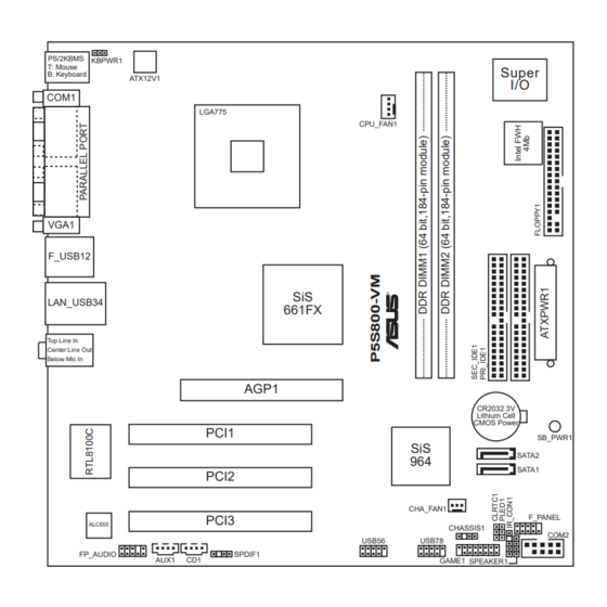
Page 19: Motherboard Layout
1.5.3 1.5.3 1.5.3 Motherboard layout Motherboard layout Motherboard layout 1.5.3 1.5.3 Motherboard layout Motherboard layout PS/2KBMS KBPWR1 T: Mouse B: Keyboard ATX12V1 COM1 LGA775 VGA1 F_USB12 LAN_USB34 Top:Line In Center:Line Out Below:Mic In PCI1 PCI2 PCI3 ALC655 FP_AUDIO AUX1 A S U S P 5 S 8 0 0 - V M A S U S P 5 S 8 0 0 - V M A S U S P 5 S 8 0 0 - V M A S U S P 5 S 8 0 0 - V M... -
Page 20: Central Processing Unit (Cpu)
Installling the CPU To install a CPU: Locate the CPU socket on the motherboard. P5S800-VM CPU Socket 775 Before installing the CPU, make sure that the socket box is facing towards you and the load lever is on your left. - Page 21 Press the load lever with your thumb (A) and move it to the left (B) until it is released from the retention tab. R e t e n t i o n t a b R e t e n t i o n t a b R e t e n t i o n t a b R e t e n t i o n t a b R e t e n t i o n t a b...
- Page 22 Close the load plate (A), then push the load lever (B) until it snaps into the retention tab. The CPU fits in only one correct orientation. DO NOT force the CPU into the socket to prevent bending the connectors on the socket and damaging the CPU! Notes on Intel Notes on Intel...
-
Page 23: Installling The Cpu Heatsink And Fan
1.6.2 1.6.2 Installling the CPU heatsink and fan Installling the CPU heatsink and fan 1.6.2 1.6.2 1.6.2 Installling the CPU heatsink and fan Installling the CPU heatsink and fan Installling the CPU heatsink and fan The Intel ® Pentium ® 4 LGA775 processor requires a specially designed heatsink and fan assembly to ensure optimum thermal condition and performance. - Page 24 When the fan and heatsink assembly is in place, connect the CPU fan cable to the connector on the motherboard labeled CPU_FAN1. P5S800-VM CPU fan connector Do not forget to connect the CPU fan connector! Hardware monitoring errors can occur if you fail to plug this connector.
-
Page 25: Uninstallling The Cpu Heatsink And Fan
1.6.3 1.6.3 Uninstalling the CPU heatsink and fan Uninstalling the CPU heatsink and fan 1.6.3 1.6.3 1.6.3 Uninstalling the CPU heatsink and fan Uninstalling the CPU heatsink and fan Uninstalling the CPU heatsink and fan To uninstall the CPU heatsink and fan: Disconnect the CPU fan cable from the connector on the motherboard labeled... - Page 26 Remove the heatsink and fan assembly from the motherboard. Rotate each fastener clockwise to reset the orientation. The narrow end of the groove should point outward after resetting. (The photo shows the groove shaded for emphasis.) 1 - 1 4 1 - 1 4 1 - 1 4 1 - 1 4...
-
Page 27: System Memory
Inline Memory Modules (DIMM) sockets. You may install 128 MB, 256 MB, 512 MB and 1 GB unbuffered non-ECC DDR DIMMs into the DIMM sockets. The following figure illustrates the location of the sockets: P5S800-VM 184-pin DDR DIMM sockets 1.7.2 1.7.2 1.7.2... - Page 28 DDR Qualified Vendors List DDR Qualified Vendors List DDR Qualified Vendors List DDR Qualified Vendors List DDR Qualified Vendors List S i z e S i z e S i z e S i z e S i z e V e n d o r V e n d o r V e n d o r...
-
Page 29: Installing A Dimm
1.7.3 1.7.3 1.7.3 Installing a DIMM Installing a DIMM Installing a DIMM 1.7.3 1.7.3 Installing a DIMM Installing a DIMM Make sure to unplug the power supply before adding or removing DIMMs or other system components. Failure to do so may cause severe damage to both the motherboard and the components. -
Page 30: Expansion Slots
Expansion slots In the future, you may need to install expansion cards. The following sub-sections describe the slots and the expansion cards that they support. Make sure to unplug the power cord before adding or removing expansion cards. Failure to do so may cause you physical injury and damage motherboard components. -
Page 31: Interrupt Assignments
1.8.3 1.8.3 1.8.3 Interrupt assignments Interrupt assignments Interrupt assignments 1.8.3 1.8.3 Interrupt assignments Interrupt assignments Standard interrupt assignments Standard interrupt assignments Standard interrupt assignments Standard interrupt assignments Standard interrupt assignments I R Q I R Q P r i o r i t y P r i o r i t y I R Q I R Q... -
Page 32: Pci Slots
AGP slot on your motherboard. Install only 1.5 V or 0.8 V AGP cards on this motherboard! 3.3V AGP cards are not supported in this motherboard. P5S800-VM Accelerated Graphics Port (AGP) 1 - 2 0 1 - 2 0... -
Page 33: Clear Rtc Ram
Except when clearing the RTC RAM, never remove the cap on CLRTC jumper default position. Removing the cap will cause system boot failure! P5S800-VM Clear RTC RAM You do not need to clear the RTC when the system hangs due to overclocking. -
Page 34: 1.10 Connectors
(the default is the Space Bar). This feature requires an ATX power supply that can supply at least 1A on the +5VSB lead, and a corresponding setting in the BIOS. P5S800-VM Keyboard power setting 1.10 Connectors 1.10.1 1.10.1... -
Page 35: Lan Port Led Indications
LAN port LED indications LAN port LED indications LAN port LED indications LAN port LED indications LAN port LED indications A C T / L I N K L E D A C T / L I N K L E D A C T / L I N K L E D A C T / L I N K L E D A C T / L I N K L E D... -
Page 36: Internal Connectors
Pin 5 on the connector is removed to prevent incorrect cable connection when using an FDD cable with a covered Pin 5. P5S800-VM Floppy disk drive connector 2 . 2 . P r i m a r y I D E c o n n e c t o r ( 4 0 - 1 p i n P R I _ I D E 1 , S E C _ I D E 1 ) -
Page 37: Hard Disk Drives
This 4-pin connector is for the chassis-mounted system warning speaker. The speaker allows you to hear system beeps and warnings. P5S800-VM Speaker out connector A S U S P 5 S 8 0 0 - V M A S U S P 5 S 8 0 0 - V M... - Page 38 This connector is for the S/PDIF audio module to allow digital sound output. Connect one end of the S/PDIF audio cable to this connector and the other end to the S/PDIF module. P5S800-VM Digital audio connector The S/PDIF out module is purchased separately. 1 - 2 6...
- Page 39 The system may become unstable or may not boot up if the power is inadequate. P5S800-VM ATX power connectors 8 . 8 . P o w e r L E D c o n n e c t o r ( 3 - 1 p i n P L E D 1 )
- Page 40 I n t e r n a l a u d i o c o n n e c t o r s ( 4 - p i n C D 1 , A U X 1 ) These connectors allow you to receive stereo audio input from sound sources such as a CD-ROM, TV tuner, MPEG card or modem. P5S800-VM Internal audio connectors 1 0 . 1 0 .
- Page 41 This connector is for a chassis-mounted front panel audio I/O module that supports legacy AC ‘97 audio standard. Connect one end of the front panel audio I/O module cable to this connector. P5S800-VM Front panel audio connector 1 2 . 1 2 .
- Page 42 By default, the pins labeled “Chassis Signal” and “Ground” are shorted with a jumper cap. Remove the jumper caps only when you intend to use the chassis intrusion detection feature. P5S800-VM Chassis intrusion connector 1 - 3 0 1 - 3 0...
-
Page 43: System Panel Connector
S y s t e m p a n e l c o n n e c t o r ( 1 0 - 1 p i n F _ P A N E L 1 ) This connector supports several chassis-mounted functions. P5S800-VM System panel connector The sytem panel connector is color-coded for easy connection. Refer to the connector description below for details. - Page 44 1 - 3 2 1 - 3 2 1 - 3 2 1 - 3 2 1 - 3 2 C h a p t e r 1 : P r o d u c t i n t r o d u c t i o n C h a p t e r 1 : P r o d u c t i n t r o d u c t i o n C h a p t e r 1 : P r o d u c t i n t r o d u c t i o n C h a p t e r 1 : P r o d u c t i n t r o d u c t i o n...
-
Page 45: Chapter 2: Bios Setup
This chapter tells how to change the system settings through the BIOS Setup menus. Detailed descriptions of the BIOS parameters are also provided. A S U S P 5 S 8 0 0 - V M A S U S P 5 S 8 0 0 - V M A S U S P 5 S 8 0 0 - V M A S U S P 5 S 8 0 0 - V M A S U S P 5 S 8 0 0 - V M... -
Page 46: Managing And Updating Your Bios
Managing and updating your BIOS The following utilities allow you to manage and update the motherboard Basic Input/Output System (BIOS) setup. A S U S A F U D O S A S U S A F U D O S A S U S A F U D O S A S U S A F U D O S (Updates the BIOS in DOS mode using a bootable A S U S A F U D O S... -
Page 47: Asus Ez Flash Utility
d. From the Open field, type D:\bootdisk\makeboot a: assuming that D: is your optical drive. e. Press <Enter>, then follow screen instructions to continue. Copy the original or the latest motherboard BIOS file to the bootable floppy disk. 2.1.2 2.1.2 2.1.2 ASUS EZ Flash utility ASUS EZ Flash utility... -
Page 48: Copying Current Bios
2.1.3 2.1.3 AFUDOS utility AFUDOS utility 2.1.3 2.1.3 2.1.3 AFUDOS utility AFUDOS utility AFUDOS utility The AFUDOS utility allows you to update the BIOS file in DOS environment using a bootable floppy disk with the updated BIOS file. This utility also allows you to copy the current BIOS file that you can use as backup when the BIOS fails or gets corrupted during the updating process. - Page 49 Updating the BIOS file Updating the BIOS file Updating the BIOS file Updating the BIOS file Updating the BIOS file To update the BIOS file using the AFUDOS utility: Visit the ASUS website (www.asus.com) and download the latest BIOS file for the motherboard. Save the BIOS file to a bootable floppy disk. Write the BIOS filename on a piece of paper.
-
Page 50: Asus Crashfree Bios 2 Utility
2.1.4 2.1.4 ASUS CrashFree BIOS 2 utility ASUS CrashFree BIOS 2 utility 2.1.4 2.1.4 2.1.4 ASUS CrashFree BIOS 2 utility ASUS CrashFree BIOS 2 utility ASUS CrashFree BIOS 2 utility The ASUS CrashFree BIOS 2 is an auto recovery tool that allows you to restore the BIOS file when it fails or gets corrupted during the updating process. - Page 51 Recovering the BIOS from the support CD Recovering the BIOS from the support CD Recovering the BIOS from the support CD Recovering the BIOS from the support CD Recovering the BIOS from the support CD To recover the BIOS from the support CD: Remove any floppy disk from the floppy disk drive, then turn on the system.
-
Page 52: Asus Update Utility
2.1.5 2.1.5 ASUS Update utility ASUS Update utility 2.1.5 2.1.5 2.1.5 ASUS Update utility ASUS Update utility ASUS Update utility The ASUS Update is a utility that allows you to manage, save, and update the motherboard BIOS in Windows allows you to: •... - Page 53 Updating the BIOS through the Internet Updating the BIOS through the Internet Updating the BIOS through the Internet Updating the BIOS through the Internet Updating the BIOS through the Internet To update the BIOS through the Internet: Launch the ASUS Update utility from the Windows S t a r t >...
- Page 54 From the FTP site, select the BIOS version that you wish to download. Click Next. Follow the screen instructions to complete the update process. The ASUS Update utility is capable of updating itself through the Internet. Always update the utility to avail all its features.
-
Page 55: Bios Setup Program
BIOS setup program This motherboard supports a programmable firmware chip that you can update using the provided utility described in section “ 2.1 Managing and updating your BIOS.” Use the BIOS Setup program when you are installing a motherboard, reconfiguring your system, or prompted to “Run Setup.” This section explains how to configure your system using this utility. -
Page 56: Bios Menu Screen
2.2.1 2.2.1 BIOS menu screen BIOS menu screen 2.2.1 2.2.1 2.2.1 BIOS menu screen BIOS menu screen BIOS menu screen M e n u i t e m s M e n u i t e m s M e n u i t e m s M e n u i t e m s M e n u i t e m s M e n u b a r... -
Page 57: Menu Items
2.2.4 2.2.4 Menu items Menu items 2.2.4 2.2.4 2.2.4 Menu items Menu items Menu items The highlighted item on the menu bar displays the specific items for that menu. For example, selecting M a i n M a i n M a i n M a i n shows the M a i n... -
Page 58: Main Menu
Main menu When you enter the BIOS Setup program, the Main menu screen appears, giving you an overview of the basic system information. Refer to section “2.2.1 BIOS menu screen” for information on the menu screen items and how to navigate through them. System Time System Date Legacy Diskette A... -
Page 59: Primary And Secondary Ide Master/Slave
2.3.4 2.3.4 2.3.4 Primary and Secondary IDE Master/Slave Primary and Secondary IDE Master/Slave Primary and Secondary IDE Master/Slave 2.3.4 2.3.4 Primary and Secondary IDE Master/Slave Primary and Secondary IDE Master/Slave While entering Setup, the BIOS automatically detects the presence of IDE devices. -
Page 60: Onchip Sata Controller
PIO Mode [Auto] PIO Mode [Auto] PIO Mode [Auto] PIO Mode [Auto] PIO Mode [Auto] Selects the PIO mode. Configuration options: [Auto] [0] [1] [2] [3] [4] SMART Monitoring [Auto] SMART Monitoring [Auto] SMART Monitoring [Auto] SMART Monitoring [Auto] SMART Monitoring [Auto] Sets the Smart Monitoring, Analysis, and Reporting Technology. -
Page 61: Advanced Menu
Advanced menu The Advanced menu items allow you to change the settings for the CPU and other system devices. Take caution when changing the settings of the Advanced menu items. Incorrect field values may cause the system to malfunction. JumperFree Configuration CPU Configuration Chipset Onboard Devices Configuration... -
Page 62: Cpu Configuration
The A G P / P C I F r e q u e n c y A G P / P C I F r e q u e n c y A G P / P C I F r e q u e n c y A G P / P C I F r e q u e n c y A G P / P C I F r e q u e n c y item appears when you set the AI Overclock Tuner to [Overclock 5%, 10%, 20%, or 30%]. - Page 63 Execute Disable Function [Disabled] Execute Disable Function [Disabled] Execute Disable Function [Disabled] Execute Disable Function [Disabled] Execute Disable Function [Disabled] This item allows you to enable or disable the No-Execution Page Protection technology, which can force the XD feature flag to always return to 0. Configuration options: [Disabled] [Enabled] Hardware Prefetcher [Enabled] Hardware Prefetcher [Enabled]...
-
Page 64: Chipset
2.4.3 2.4.3 2.4.3 Chipset Chipset Chipset 2.4.3 2.4.3 Chipset Chipset The Chipset menu items allow you to change the advanced chipset settings. Select an item then press <Enter> to display the sub-menu. NorthBridge SiS661FX Configuration SouthBridge SiS964 Configuration NorthBridge SiS661FX Configuration NorthBridge SiS661FX Configuration NorthBridge SiS661FX Configuration NorthBridge SiS661FX Configuration... -
Page 65: Onboard Devices Configuration
Graphics Win Size [64MB] Graphics Win Size [64MB] Graphics Win Size [64MB] Graphics Win Size [64MB] Graphics Win Size [64MB] Allows you to select the size of mapped memory for AGP graphic data. Configuration options: [32MB] [64MB] [128MB] AGP Fast Write Control [Disabled] AGP Fast Write Control [Disabled] AGP Fast Write Control [Disabled] AGP Fast Write Control [Disabled]... - Page 66 Parallel Port Address [378] Parallel Port Address [378] Parallel Port Address [378] Parallel Port Address [378] Parallel Port Address [378] Allows you to select the Parallel Port base addresses. Configuration options: [Disabled] [378] [278] [3BC] Parallel Port Mode [ECP] Parallel Port Mode [ECP] Parallel Port Mode [ECP] Parallel Port Mode [ECP] Parallel Port Mode [ECP]...
-
Page 67: Pci Pnp
2.4.5 2.4.5 2.4.5 PCI PnP PCI PnP PCI PnP 2.4.5 2.4.5 PCI PnP PCI PnP The PCI PnP menu items allow you to change the advanced settings for PCI/PnP devices. The menu includes setting IRQ and DMA channel resources for either PCI/PnP or legacy ISA devices, and setting the memory size block for legacy ISA devices. -
Page 68: Usb Configuration
PCI IDE BusMaster [Enabled] PCI IDE BusMaster [Enabled] PCI IDE BusMaster [Enabled] PCI IDE BusMaster [Enabled] PCI IDE BusMaster [Enabled] Allows BIOS to use PCI bus mastering when reading/writing to IDE devices. Configuration options: [Disabled] [Enabled] IRQ xx assigned to [Available] IRQ xx assigned to [Available] IRQ xx assigned to [Available] IRQ xx assigned to [Available]... -
Page 69: Legacy Usb Support [Auto]
Legacy USB Support [Auto] Legacy USB Support [Auto] Legacy USB Support [Auto] Legacy USB Support [Auto] Legacy USB Support [Auto] Allows you to enable or disable support for legacy USB devices. Setting to Auto allows the system to detect the presence of USB devices at startup. If detected, the USB controller legacy mode is enabled. -
Page 70: Power Menu
Power menu The Power menu items allow you to change the settings for the Advanced Configuration and Power Interface (ACPI) and the Advanced Power Management (APM). Select an item then press <Enter> to display the configuration options. Suspend Mode ACPI 2.0 Support ACPI APIC Support APM Configuration Hardware Monitor... -
Page 71: Apm Configuration
2.5.5 2.5.5 2.5.5 APM Configuration APM Configuration APM Configuration 2.5.5 2.5.5 APM Configuration APM Configuration Power Button Mode Restore on AC Power Loss Power On By PS2 Keyboard Power On By PS2 Mouse Power On by PCI Devices Power On By External Modems Power On By RTC Alarm Power Button Mode [On/Off] Power Button Mode [On/Off]... -
Page 72: Hardware Monitor
Power On By External Modems [Disabled] Power On By External Modems [Disabled] Power On By External Modems [Disabled] Power On By External Modems [Disabled] Power On By External Modems [Disabled] This allows either settings of [Enabled] or [Disabled] for powering up the computer when the external modem receives a call while the computer is in Soft-off mode. - Page 73 CPU Q-Fan Control [Disabled] CPU Q-Fan Control [Disabled] CPU Q-Fan Control [Disabled] CPU Q-Fan Control [Disabled] CPU Q-Fan Control [Disabled] Allows you to enable or disable the CPU Q-Fan Control feature that smarly adjusts the fan speeds for more efficient system operation. Configuration options: [Disabled] [Enabled] The two succeeding iems appear when the C P U Q - F a n C o n t r o l is set to [Enabled].
-
Page 74: Boot Menu
Boot menu The Boot menu items allow you to change the system boot options. Select an item then press <Enter> to display the sub-menu. Boot Settings Boot Device Priority Boot Settings Configuration Security 2.6.1 2.6.1 2.6.1 Boot Device Priority Boot Device Priority Boot Device Priority 2.6.1 2.6.1... -
Page 75: Boot Settings Configuration
2.6.3 2.6.3 2.6.3 Boot Settings Configuration Boot Settings Configuration Boot Settings Configuration 2.6.3 2.6.3 Boot Settings Configuration Boot Settings Configuration Boot Settings Configuration Quick Boot Full Screen Logo AddOn ROM Display Mode Bootup Num-Lock PS/2 Mouse Support Wait For ‘F1’ If Error Hit ‘DEL’... -
Page 76: Interrupt 19 Capture [Disabled]
Interrupt 19 Capture [Disabled] Interrupt 19 Capture [Disabled] Interrupt 19 Capture [Disabled] Interrupt 19 Capture [Disabled] Interrupt 19 Capture [Disabled] When set to [Enabled], this function allows the option ROMs to trap Interrupt 19. Configuration options: [Disabled] [Enabled] 2.6.4 2.6.4 2.6.4 Security Security... -
Page 77: Change User Password
After you have set a supervisor password, the other items appear to allow you to change other security settings. Security Settings Supervisor Password : Not Installed User Password : Not Installed Change Supervisor Password User Access Level Change User Password Clear User Password Password Check User Access Level (Full Access]... -
Page 78: Password Check [Setup]
Password Check [Setup] Password Check [Setup] Password Check [Setup] Password Check [Setup] Password Check [Setup] When set to [Setup], BIOS checks for user password when accessing the Setup utility. When set to [Always], BIOS checks for user password both when accessing Setup and booting the system. Configuration options: [Setup] [Always] Exit menu The Exit menu items allow you to load the optimal or failsafe default values... -
Page 79: Exit & Discard Changes
If you attempt to exit the Setup program without saving your changes, the program prompts you with a message asking if you want to save your changes before exiting. Press <Enter> to save the changes while exiting. Exit & Discard Changes Exit &... - Page 80 2 - 3 6 2 - 3 6 2 - 3 6 2 - 3 6 2 - 3 6 C h a p t e r 2 : B I O S s e t u p C h a p t e r 2 : B I O S s e t u p C h a p t e r 2 : B I O S s e t u p C h a p t e r 2 : B I O S s e t u p C h a p t e r 2 : B I O S s e t u p...
-
Page 81: Chapter 3: Software Support
This chapter describes the contents of the support CD that comes with the motherboard package. A S U S P 5 S 8 0 0 - V M A S U S P 5 S 8 0 0 - V M A S U S P 5 S 8 0 0 - V M A S U S P 5 S 8 0 0 - V M A S U S P 5 S 8 0 0 - V M... -
Page 82: Installing An Operating System
Installing an operating system This motherboard supports Windows operating systems (OS). Always install the latest OS version and corresponding updates to maximize the features of your hardware. • Motherboard settings and hardware options vary. Use the setup procedures presented in this chapter for reference only. Refer to your OS documentation for detailed information. -
Page 83: Drivers Menu
3.2.2 3.2.2 3.2.2 Drivers menu Drivers menu Drivers menu 3.2.2 3.2.2 Drivers menu Drivers menu The drivers menu shows the available device drivers if the system detects installed devices. Install the necessary drivers to activate the devices. SIS Chipset Driver SIS Chipset Driver SIS Chipset Driver SIS Chipset Driver... -
Page 84: Utilities Menu
3.2.3 3.2.3 Utilities menu Utilities menu 3.2.3 3.2.3 3.2.3 Utilities menu Utilities menu Utilities menu The Utilities menu shows the applications and other software that the motherboard supports. ASUS PC Probe ASUS PC Probe ASUS PC Probe ASUS PC Probe ASUS PC Probe This smart utility monitors the fan speed, CPU temperature, and system voltages, and alerts you of any detected problems. -
Page 85: Asus Contact Information
3.2.4 3.2.4 ASUS Contact information ASUS Contact information 3.2.4 3.2.4 3.2.4 ASUS Contact information ASUS Contact information ASUS Contact information Click the C o n t a c t C o n t a c t C o n t a c t tab to display the ASUS contact information. You can C o n t a c t C o n t a c t also find this information on the inside front cover of this user guide. - Page 86 3 - 6 3 - 6 3 - 6 3 - 6 3 - 6 C h a p t e r 3 : S o f t w a r e s u p p o r t C h a p t e r 3 : S o f t w a r e s u p p o r t C h a p t e r 3 : S o f t w a r e s u p p o r t C h a p t e r 3 : S o f t w a r e s u p p o r t C h a p t e r 3 : S o f t w a r e s u p p o r t...
Need help?
Do you have a question about the P5S800-VM and is the answer not in the manual?
Questions and answers