Advertisement
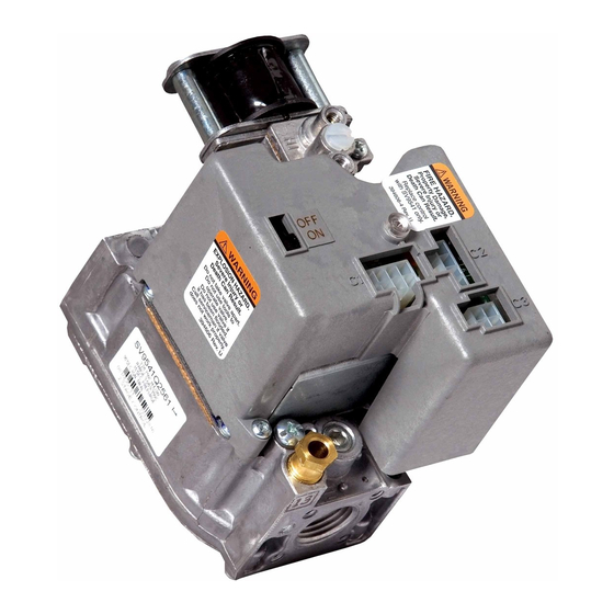
SV9541, SV9641 SmartValve™
System Controls
APPLICATION
The SV9541 and SV9641 SmartValve™ System Controls
combine gas flow control and electronic intermittent
pilot sequencing functions into a single unit. The Q3450
or Q3480 Pilot hardware supplies the low voltage igniter,
flame sensor and pilot burner. These ignition system
controls provide all gas ignition safety functions by
controlling gas flow, ignition source, and a 120 Vac or
240 Vac combustion air blower. The controls also
monitor the appliance airflow proving switch and limit
string to assure proper appliance operation, and provide
prepurge, postpurge, and timed trial for pilot ignition
with 100 percent shutoff and continuous retry. A
diagnostic LED indicates system status.
These controls communicate directly with an electronic
fan timer (ST9160 Electronic Fan Timer for single stage
applications; ST9162 Electronic Fan Timer for two-stage
applications) in typical forced warm air furnace
applications. They also interface with the 208907
Size
(Inlet x
Model
Outlet) (in.)
SV9541
1/2 x 1/2
b,c
3/4 x 3/4
SV9641
a
Capacity based on 1000 Btu/ft
at 0.25 kPa pressure drop).
b
Capacity is reduced by 5 percent when using an outlet screen.
c
Valves are guaranteed at only 77 percent of the rating.
d
Minimum regulation for LP gas is 40,000 Btuh.
Table 2. Gas Capacity Conversion Factor.
Gas
Specific Gravity
Manufactured
Mixed
Propane
Table 1. Valve Capacity
AGA Certified Capacity for
Natural Gas
ft3/hr
m3/hr
150
300
3
, 0.64 sp gr natural gas at 1 in. wc pressure drop (37.3 MJ/m
Multiply Listed
Capacities By
0.60
0.516
0.70
0.765
1.53
1.62
Terminal Board, providing compatibility with power
stealing thermostats. Or, they directly interface with the
appropriate power supplies and a system thermostat for
additional appliance applications. When controlled
directly by a thermostat, these controls do not provide a
postpurge function, because power to the control is
removed when the thermostat call for heat ends.
The SV9541 and SV9641 Systems are suitable for a wide
range of fan-assisted combustion gas-fired appliances
including furnaces, rooftop furnaces, boilers, unit
heaters, infrared heaters, water heaters and commercial
cooking appliances. The specific application of the
SmartValve™ System is determined by the appliance
manufacturer.
SmartValve™ System controls are available in a range of
valve capacities, see Table 1. (Table 2 provides gas
capacity conversion factors.) The suffix letter indicates
temperature range and regulator type, see Table 3.
a
.
AGA Certified Minimum
Regulation for Natural Gas
ft3/hr
4.2
d
20
8.5
Table 3. Model Number Suffix Letter Designation.
Model No.
Suffix Letter
M
Q
INSTALLATION INSTRUCTIONS
AGA Certified Maximum
Regulation for Natural Gas
m3/hr
ft3/hr
200
0.6
415
3
, 0.6 sp gr natural gas
Ambient
Temperature
Range
-40°F to 175°F
(-40°C to 79°C)
m3/hr
5.7
11.8
Pressure
Regulator Type
Standard
Two-stage
69-2012-01
Advertisement
Table of Contents

Related Manuals for resideo SmartValve SV9541


Summary of Contents for resideo SmartValve SV9541
- Page 1 SV9541, SV9641 SmartValve™ System Controls INSTALLATION INSTRUCTIONS Terminal Board, providing compatibility with power APPLICATION stealing thermostats. Or, they directly interface with the appropriate power supplies and a system thermostat for The SV9541 and SV9641 SmartValve™ System Controls additional appliance applications. When controlled combine gas flow control and electronic intermittent directly by a thermostat, these controls do not provide a pilot sequencing functions into a single unit.
-
Page 2: Specifications
These Regulation Range: applications require Resideo Engineering review; contact See Table 1. your Sales Representative for assistance. Natural-LP Gas Conversion Kits: See Table 4. -
Page 3: Installation
SV9541, SV9641 SMARTVALVE™ SYSTEM CONTROLS High Humidity or Dripping Water CAUTION Dripping water can cause the control to fail. Never install Electrical Shock or Equipment Damage Hazard. an appliance where water can drip on the control. In Can shock individuals or short equipment addition, high ambient humidity can cause the control to circuitry. - Page 4 SV9541, SV9641 SMARTVALVE™ SYSTEM CONTROLS 3. Install a sediment trap in the supply line to the Bushings ignition system control. See Fig. 2. 1. Remove the seal over the ignition system control inlet or outlet. Install Control 2. Apply a moderate amount of good quality pipe compound to the bushing, leaving two end threads 1.
- Page 5 SV9541, SV9641 SMARTVALVE™ SYSTEM CONTROLS 3. Unscrew the brass compression fitting from the pilot outlet (Fig. 5). Slip the fitting over the tubing IGNITION and slide out of the way. See Fig. 6. IMPERFECT SYSTEM 4. Push the tubing into the pilot gas tapping on the THREADS CONTROL outlet end of the control until it bottoms.
- Page 6 SV9541, SV9641 SMARTVALVE™ SYSTEM CONTROLS HI-LO ADJUSTMENT SCREWS IGNITER (UNDER CAP) CONNECTOR LINE VOLTAGE PRESSURE REGULATOR REGULATOR CONNECTOR ADJUSTMENT (UNDER VENT COVER CAP SCREW) INLET PRESSURE OUTLET PRESSURE OUTLET INLET INLET IGNITION SYSTEM CONTROLS PILOT M10965A CONTROL SWITCH CONNECTOR OUTLET Fig.
- Page 7 SV9541, SV9641 SMARTVALVE™ SYSTEM CONTROLS AUXILIARY TO 120/240 VAC, 60 HZ 40 VA LIMIT SWITCH POWER SUPPLY TRANSFORMER (OPTIONAL) (HOT) ROLLOUT SWITCH ELECTRONIC AIR PROVING AIR CLEANER SWITCH COMBUSTION LIMIT AIR BLOWER XFMR CONT COOL SWITCH NEUTRALS CIRCULATING SV9440 ST9160 SV9540 ELECTRONIC SV9640...
- Page 8 SV9541, SV9641 SMARTVALVE™ SYSTEM CONTROLS TO 120/240 VAC, 60 HZ AUXILIARY 40 VA POWER SUPPLY LIMIT SWITCH TRANSFORMER (OPTIONAL) (HOT) ROLLOUT SWITCH ELECTRONIC AIR PROVING AIR CLEANER SWITCH COMBUSTION LIMIT XFMR CONT COOL AIR BLOWER SWITCH NEUTRALS CIRCULATING SV9440 ST9160 SV9540 ELECTRONIC SV9640...
- Page 9 SV9541, SV9641 SMARTVALVE™ SYSTEM CONTROLS ROLLOUT SWITCH AIR PROVING COMBUSTION SWITCH 24V THERMOSTAT LIMIT AIR BLOWER SWITCH SV9440 SV9540 SV9640 AQUASTAT ® CONTROL TO 120 VAC, 60 HZ POWER SUPPLY DATA (HOT) 24 VAC Q3450 R8285D CONTROL CENTER IGNITER- CIRCULATOR SENSOR POWER SUPPLY.
-
Page 10: Startup And Checkout
SV9541, SV9641 SMARTVALVE™ SYSTEM CONTROLS PRESSURE ROLLOUT SWITCH SWITCH CONTINUOUS FAN SPEED INDUCER LOW NEUTRAL INDUCER HIGH INDUCER LIMIT COOL SPEED NEUTRAL MAIN SWITCH Q3450 BLOWER IGNITER- HEAT HIGH SPEED SENSOR HEAT LOW SPEED SV9440 SV9540 SV9640 SMART VALVE II DATA 24 VAC HSI N... - Page 11 SV9541, SV9641 SMARTVALVE™ SYSTEM CONTROLS 2. IF CHECKING GAS INPUT BY CLOCKING GAS Gas Leak Test METER: Make certain there is no gas flow 1. Paint pipe connections upstream of the ignition through the meter other than to the appliance system control with rich soap and water solution.
- Page 12 SV9541, SV9641 SMARTVALVE™ SYSTEM CONTROLS 6. After high pressure is checked, check low pressure Two-Stage (Q) Models regulation by removing the wire from terminal W2 Two-stage models allow independent adjustment of high of the ST9162 fan timer (to prevent ignition control and low pressure settings.
-
Page 13: Maintenance
SV9541, SV9641 SMARTVALVE™ SYSTEM CONTROLS MAINTENANCE SERVICE WARNING WARNING Fire or Explosion Hazard. Fire or Explosion Hazard. Can cause property damage, severe injury or Can cause property damage, severe injury or death. death. Do not disassemble the ignition control: it Do not disassemble the ignition control: it contains no replaceable components. - Page 14 SV9541, SV9641 SMARTVALVE™ SYSTEM CONTROLS SV9541; SV9641 INTERMITTENT PILOT SmartValve™ POWER APPLIED TO APPLIANCE SYSTEM CONTROL SEQUENCE OF OPERATION WITH ST9160 ELECTRONIC FAN TIMER OR 208907 TERMINAL BOARD THERMOSTAT CALLS FOR HEAT AIR PROVING SWITCH PROVED WAIT FOR AIR PROVING OPEN? SWITCH TO OPEN COMBUSTION AIR BLOWER ON...
-
Page 15: Troubleshooting
SV9541, SV9641 SMARTVALVE™ SYSTEM CONTROLS SV9541; SV9641 INTERMITTENT PILOT SmartValve™ SYSTEM CONTROL SEQUENCE OF OPERATION WITH ST9162A 2-STAGE ELECTRONIC FAN TIMER POWER APPLIED TO APPLIANCE THERMOSTAT CALLS FOR HEAT HI AND LOW AIR PROVING WAIT FOR AIR PROVING SWITCHES PROVED OPEN? SWITCH TO OPEN COMBUSTION AIR BLOWER ON HIGH SPEED... - Page 16 SV9541, SV9641 SMARTVALVE™ SYSTEM CONTROLS 1. Check the system thermostat to make sure it is 3. Observe the LED indicator on the SV9541 or calling for heat. (Do not cycle the thermostat on SV9641; check and repair system as noted in and off at this time.) Table 9 or 10.
- Page 17 SV9541, SV9641 SMARTVALVE™ SYSTEM CONTROLS Table 10. Troubleshooting with LED indicator assistance for ignition controls using ST9160 Fan Timer or 208907 Terminal Board LED Status Indicates Check/Repair No power to system control. 1. Line voltage input power at 120 VAC LINE and L2 connectors on ST9162 Electric Fan Timer (EFT).
- Page 18 SV9541, SV9641 SMARTVALVE™ SYSTEM CONTROLS 4. After LED flash code analysis and appliance repair 1. Make sure the appliance power is on and any are complete, turn the thermostat below room manually operated gas cock on the appliance is temperature for 10 seconds; turn the thermostat open.
- Page 19 SV9541, SV9641 SMARTVALVE™ SYSTEM CONTROLS Table 11. Troubleshooting without LED indicator assistance for ignition controls using an ST9160 Fan Timer or 208907 Terminal Board. (Continued) Check/Repair Pilot lights during trial Main gas does not flow. 1. Line voltage to L1 terminal of ST9160 or for ignition.
-
Page 20: Instructions To The Homeowner
Resideo Technologies, Inc. 1985 Douglas Drive North, Golden Valley, MN 55422 1-800-468-1502 69-2012—01 M.S. Rev. 06-20 | Printed in United States www.resideo.com © 2020 Resideo Technologies, Inc. All rights reserved. This product is manufactured by Resideo Technologies, Inc. and its affiliates.
Need help?
Do you have a question about the SmartValve SV9541 and is the answer not in the manual?
Questions and answers