Table of Contents
Advertisement
Quick Links
Advertisement
Table of Contents

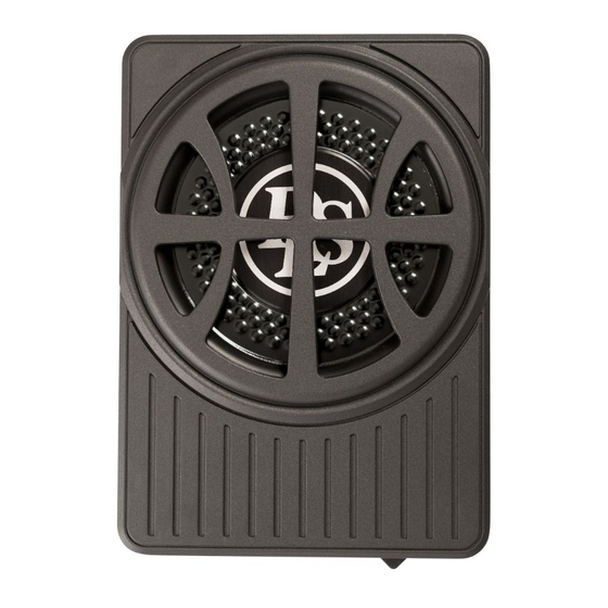
Summary of Contents for DLS ACW10
- Page 2 Specifications……………………….... use of the above amplifiers. Your DLS amplifiers must be installed correctly in order to perform at its best. This manual will This product must be returned to the show you how to install the amplifier like a pro.
-
Page 3: Power Input Terminal
1. Power Status Led 6. Input Gain Control This bi-color LED glows green when power is After you have installed your system, turn this on and no problems are present. lf one of the control to minimum. protection circuits comes on, it will change to Turn the head unit on (and the subwoofer will red. - Page 4 NOTE: Do not connect BOTH the high level and low level inputs from your receiver to your amplifier at the same time. Low Level lnput Wiring Low-level (RCA) input wiring is prefered for best audio performance. Most trunk or hatchback installations will require a 15-20 feet RCA cable, while pickup trucks and under-seat installations will require a 6-12 feet RCA cable.
-
Page 5: Power Terminal
Power Terminal Connect to a good chassis ground. The ground connection should be clean, unpainted metal to provide a good electrical connection. Use a wire brush, a scraper or a piece of an abrasive sheet to clean the metal. Remote Terminal Connect the remote terminal to the remote output of the head unit. -
Page 6: Installation
Installation We include a fixing kit to ensure the subwoofer remains securely mounted. Two types of installation are possible. Under the seat 1 - The seat must be positioned in its normal fixed position. 2 - Decide the best location possible that suits your automobile and space available, checking that the enclosure doesn’t restrict the seat mobility. - Page 7 Installation 4 Mounting Tabs 25mm supplied screws Pre Drilled Mounting hole...
- Page 8 Installation In the trunk 1 - Rear seats must be positioned in their normal fixed position. 2 - Decide the best location possible that suits your automobile and space available. The best and most secure location for optimum sound quality is behind the rear seats,in the trunk floor (see Figure 1 ).
- Page 9 Installation 4 Screws M6*8 4 Mounting Tabs Pre Drilled Mounting hole 25mm supplied screws...
- Page 10 Troubleshooting Testing lf you experience operation or performance problems with this product, com- pare your installation with the electrical wiring diagram on the previous pages. lf problems persist, read the following troubleshooting tips which may help eliminate the problems. Check to make sure you have a good ground connection. Amplifier will Check that the Remote lnput {Turn-On) has at least 5VDC.
- Page 11 Battery If noise remains regardless of cable 1,5 Volt position, try to use so called Quasi- balanced signal cables. DLS PRO- cables are Quasibalanced. NOTE! Tweeters can not be tested this way, dou- Professional Tip: ble check the connections instead.


Need help?
Do you have a question about the ACW10 and is the answer not in the manual?
Questions and answers
hi i have two dls acw10 installed in my car, i have noticed one of the amps had blown the fuse, i have tried replacing the fuse however it does not switch on, it indicated protect mode and then both leds are off. what could the cause be ?
The DLS ACW10 amplifier could go into protect mode and not turn on after replacing the blown fuse due to the following reasons:
1. Short circuits on the speaker leads.
2. Overdriving from the head unit (volume set too high).
3. Faulty amplifier requiring servicing.
4. Improper grounding.
5. Remote input (Turn-On) voltage less than 5VDC.
These issues should be checked and corrected before repowering the amplifier.
This answer is automatically generated