Table of Contents
Advertisement
Quick Links
Advertisement
Table of Contents

Related Manuals for Mindray iMEC8 Vet

Summary of Contents for Mindray iMEC8 Vet
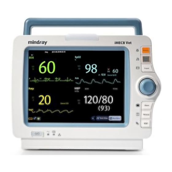
- Page 1 Vet Portable Multi-Parameter Veterinary Monitor Operator’s Manual...
- Page 3 SHENZHEN MINDRAY BIO-MEDICAL ELECTRONICS CO., LTD. (hereinafter called Mindray) owns the intellectual property rights to this Mindray product and this manual. This manual may refer to information protected by copyrights or patents and does not convey any license under the patent rights of Mindray, nor the rights of others.
- Page 4 Contents of this manual are subject to changes without prior notice. All information contained in this manual is believed to be correct. Mindray shall not be liable for errors contained herein nor for incidental or consequential damages in connection with the furnishing, performance, or use of this manual.
- Page 5 Company Contact Manufacturer: Shenzhen Mindray Bio-Medical Electronics Co., Ltd. Mindray Building, Keji 12th Road South, Hi-tech industrial park, Address: Nanshan,Shenzhen 518057,P.R.China Website: www.mindray.com E-mail Address: service@mindray.com Tel: +86 755 81888998 Fax: +86 755 26582680 Distributor: Mindray DS USA, Inc. Address:...
- Page 6 This manual is based on the maximum configuration and therefore some contents may not apply to your product. If you have any question, please contact Mindray. This manual is an integral part of the product. It should always be kept close to the equipment so that it can be obtained conveniently when needed.
-
Page 7: Table Of Contents
Contents 1 Safety....................................1-1 1.1 Safety Information ....................................1-1 1.1.1 Dangers ......................................1-2 1.1.2 Warnings ......................................1-2 1.1.3 Cautions ......................................1-3 1.1.4 Notes ....................................... 1-3 1.2 Equipment Symbols ....................................1-3 2 The Basics ..................................2-1 2.1 Monitor Description ....................................2-1 2.1.1 Intended Use .................................... - Page 8 3.12.1 Monitoring Mode ..................................3-9 3.12.2 Night Mode ....................................3-9 3.12.3 Privacy Mode ....................................3-9 3.12.4 Demo Mode ..................................... 3-10 3.12.5 Standby Mode ..................................3-10 4 Managing Patients ................................. 4-1 4.1 Admitting a Patient ....................................4-1 4.2 Quick Admitting a Patient ..................................4-2 4.3 Querying and Obtaining Patient Information ..........................
- Page 9 7.1 Alarm Categories ...................................... 7-1 7.2 Alarm Levels ....................................... 7-2 7.3 Alarm Indicators ......................................7-2 7.3.1 Alarm Lamp ....................................7-2 7.3.2 Alarm Message..................................... 7-2 7.3.3 Flashing Numeric ..................................7-3 7.3.4 Audible Alarm Tones .................................. 7-3 7.3.5 Alarm Status Symbols ................................7-3 7.4 Alarm Tone Configuration ..................................
- Page 10 8.5.4 Choosing an ECG Display Screen ............................8-6 8.5.5 Changing the ECG Filter Settings ............................8-6 8.5.6 Setting the Notch Filter................................8-7 8.5.7 Changing the Pacer Reject Settings ............................8-7 8.5.8 Changing ECG Wave Settings ..............................8-7 8.5.9 Enabling Smart Lead Off ................................8-8 8.5.10 Setting the Alarm Level for ECG Lead Off Alarms ......................
- Page 11 10 Monitoring PR ................................10-1 10.1 Introduction ......................................10-1 10.2 Setting the PR Source ..................................10-1 10.3 Selecting the Active Alarm Source ..............................10-2 10.4 QRS Tone ......................................... 10-2 11 Monitoring SpO ............................... 11-1 11.1 Introduction ......................................11-1 11.2 Safety ........................................11-2 11.3 Identifying SpO Modules ..................................
- Page 12 13.1 Introduction ......................................13-1 13.2 Safety ........................................13-1 13.3 Making a Temp Measurement ................................. 13-1 13.4 Understanding the Temp Display ..............................13-2 13.5 Setting the Temperature Unit ................................13-2 14 Monitoring IBP ................................14-1 14.1 Introduction ......................................14-1 14.2 Safety ........................................14-1 14.3 Zeroing the Transducer ..................................
- Page 13 15.9 Removing Exhaust Gases from the System ..........................15-7 15.10 Zeroing the Sensor .................................... 15-7 15.10.1 For Sidestream and Microstream CO Modules ......................15-7 15.11 Calibrating the Sensor ..................................15-7 15.12 Oridion Information ..................................15-8 16 Freezing Waveforms ..............................16-1 16.1 Freezing Waveforms ....................................
- Page 14 19 Recording ...................................19-1 19.1 Using a Recorder ....................................19-1 19.2 Overview of Recording Types ................................19-1 19.3 Starting and Stopping Recordings ..............................19-2 19.4 Setting up the Recorder..................................19-2 19.4.1 Accessing the Record Setup Menu ........................... 19-2 19.4.2 Selecting Waveforms for Recording ..........................19-2 19.4.3 Setting the Realtime Recording Length ..........................
- Page 15 23.7 CO Test ........................................23-3 23.8 Calibrating the Touchscreen ................................23-4 23.9 Electrical Safety Tests ..................................23-4 24 Accessories ................................24-1 24.1 ECG Accessories ....................................24-1 24.2 SpO Accessories ....................................24-2 24.3 NIBP Accessories ....................................24-3 24.4 Temp Accessories ....................................24-3 24.5 IBP/ICP Accessories ....................................
- Page 16 F.1 Symbols ........................................F-1 F.2 Abbreviations ......................................F-2...
-
Page 17: Safety
Safety 1.1 Safety Information DANGER Indicates an imminent hazard that, if not avoided, will result in death or serious injury. WARNING Indicates a potential hazard or unsafe practice that, if not avoided, could result in death or serious injury. ... -
Page 18: Dangers
1.1.1 Dangers There are no dangers that refer to the product in general. Specific “Danger” statements may be given in the respective sections of this manual. 1.1.2 Warnings WARNING The device is intended for animal monitoring by trained personnel in the specified places. ... -
Page 19: Cautions
with the guidelines regulating the disposal of such products. If you have any questions concerning disposal of the equipment, please contact Mindray. Magnetic and electrical fields are capable of interfering with the proper performance of the equipment. For ... - Page 20 AUDIO PAUSED Graphical recorder Freeze/unfreeze waveforms Main menu NIBP start/stop key Output Equipotentiality VGA output USB connector Network connector Gas outlet Serial number Inserted direction DATE OF MANUAFACTURE This mark means that this device is fully in conformance with the Council Directive Concerning Medical Devices 84/539/EEC and 2004/108/EC.
-
Page 21: The Basics
2.1 Monitor Description 2.1.1 Intended Use The iMEC8 Vet monitor is intended to be used for monitoring, displaying, reviewing, storing and transferring of multiple physiological parameters including ECG, heart rate (HR), respiration (Resp), temperature (Temp), SpO , pulse rate (PR),... - Page 22 Alarm lamp When a physiological alarm or technical alarm occurs, this lamp will flash as defined below. High level alarms: the lamp quickly flashes red. Medium level alarms: the lamp slowly flashes yellow. Low level alarms: the lamp lights yellow without flashing. ...
-
Page 23: Side View
2.3 Side View Recorder Battery compartment gas outlet Slot for CO watertrap (sidestream) Connector for ECG cable Connector for SpO cable Connector for NIBP cuff Connector for Temp probe 1 Connector for Temp probe 2 Connector for IBP cable... -
Page 24: Rear View
2.4 Rear View Equipotential Grounding Terminal When the monitor and other devices are to be used together, their equipotential grounding terminals should be connected together, eliminating the potential difference between them. AC Power Input Multifunctional Connector It outputs defibrillator synchronization signals, nurse call signals and analogy output signals. VGA Connector It connects a secondary display, which extends the display capability of your monitor. -
Page 25: Display Screen
2.5 Display Screen This monitor adopts a high-resolution TFT LCD to display patient parameters and waveforms. A typical display screen is shown below. Patient Information Area This area shows the patient information such as bed number, patient name and patient category, indicates that no patient is admitted or the patient information is incomplete. - Page 26 Physiological Alarm Area This area shows physiological alarm messages. When multiple alarms occur, they will be displayed circularly. Select this area and the physiological alarm list will be displayed. Waveform Area This area shows measurement waveforms. The waveform name is displayed at the left upper corner of the waveform.
-
Page 27: Quickkeys
2.6 QuickKeys A QuickKey is a configurable graphical key, located at the bottom of the main screen. They give you fast access to functions. Their availability and the order in which they appear on your screen depend on how your monitor is configured. - Page 28 Perform calculations Have a split-screen view of another patient’s data Have a split-screen view of OxyCRG trends Enter the full-screen 7-lead ECG screen Enter the [Parameters] menu Start NIBP STAT measurement Enter the [Unit Setup] menu Enter the PAWP measurement screen Enter the privacy mode Enter the night mode Enter the intubation mode...
-
Page 29: Basic Operations
Mindray. If the packing case is intact, open the package and remove the equipment and accessories carefully. Check all materials against the packing list and check for any mechanical damage. Contact Mindray in case of any problem. NOTE Save the packing case and packaging material as they can be used if the equipment must be reshipped. -
Page 30: Environmental Requirements
Press the power on/off button on the monitor’s front. WARNING Do not use the monitor for any monitoring procedure on a patient if you suspect it is not working properly, or if it is mechanically damaged. Contact your service personnel or Mindray. -
Page 31: Starting Monitoring
3.2.2 Starting Monitoring Decide which measurements you want to make. Connect the required patient cables and sensors. Check that the patient cables and sensors are correctly connected. Check that the patient settings such as [Patient Cat.], [Paced], etc, are appropriate for your patient. Refer to the appropriate measurement section for details of how to perform the measurements you require. -
Page 32: Setting The Screen
touchscreen operation is disabled. 3.6 Setting the Screen You can enter the [Screen Setup] window as shown below by selecting [Main Menu]→[Screen Setup]→[Screen Layout >>]. In this window, you can allocate the positions of the parameters and waveforms. The parameters or waveforms whose positions are not allocated will not be displayed. -
Page 33: Using The On-Screen Keyboard
3.7 Using the On-screen Keyboard The onscreen keyboard enables you to enter information. Use the key to delete the previously entered character. Use the key to toggle between uppercase and lowercase letters. Select the key to confirm what you have entered and close the onscreen keyboard. ... -
Page 34: Using The Main Menu
3.9 Using the Main Menu To enter the main menu, select the [Main Menu] QuickKey or the hardkey on the monitor’s front. Most of the monitor’s operations and settings can be performed through the main menu. Other menus are similar to the main menu and contain the following parts: Heading: gives a sum-up for the current menu. -
Page 35: Changing Language
3.10.2 Changing Language Select [Main Menu]→[Maintenance >>]→[User Maintenance >>]→enter the required password. In the [User Maintenance] menu, select [Language] and then select the desired language. Restart the monitor. 3.10.3 Adjusting the Screen Brightness Select the [Main Menu]→[Screen Setup >>]→[Brightness]. Select the appropriate setting for the screen brightness. 10 is the brightest, and 1 is the least bright. If the monitor operates on battery power, using a less bright setting will prolong the battery operating time. -
Page 36: Setting Parameters
Key Volume When you press the navigation knob or the touchscreen, or the hardkeys on the panel, the monitor prompts you by making a sound of the key volume you have set. Select the [Volume Setup] QuickKey, or [Main Menu]→[Screen Setup >>]. Select [Key Volume] and then select the appropriate volume. -
Page 37: Operating Modes
3.12 Operating Modes Your monitor has different operating modes. Some are password protected. This section lists the major operating modes. 3.12.1 Monitoring Mode This is the normal, everyday working mode that you use for monitoring patients. Your monitor automatically enters the monitoring mode after being turned on. -
Page 38: Demo Mode
To cancel the privacy mode, press any key. The monitor exits the privacy mode automatically in one of the following situations: The monitor disconnects from the central station. The alarm [Battery Too Low] or [System will shut down soon. Please replace the batteries or use the ... -
Page 39: Managing Patients
Managing Patients 4.1 Admitting a Patient The monitor displays physiological data and stores it in the trends as soon as a patient is connected. This allows you to monitor a patient that is not admitted yet. However, it is recommended that you fully admit a patient so that you can clearly identify your patient, on recordings, reports and networking devices. -
Page 40: Quick Admitting A Patient
4.2 Quick Admitting a Patient Use [Quick Admit] only if you do not have the time or information to fully admit a patient. Complete the rest of the patient demographic details later. Otherwise, the symbol will always be displayed in the patient information area. Select the [Patient Setup] QuickKey, or [Main Menu]→[Patient Setup >>]. -
Page 41: Associating Patient Information
4.4 Associating Patient Information After associating patient information with HIS, the monitor will automatically update patient information if corresponding information in HIS has been changed. The monitor can associate a patient’s MRN, first name, last name, date of birth, and gender with HIS. NOTE A keyword takes effect only when being defined in eGateway. -
Page 42: Transferring A Patient
4.7 Transferring a Patient You can transfer patient data between monitors with a USB drive without re-entering the patient demographic information. Transferring of patient data enables you to understand the patient’s historical condition. The patient data that can be transferred includes: patient demographics, trend data, alarm events and parameters alarm limits. Select [Others >>] from [User Maintenance] menu. -
Page 43: Transferring Data From A Usb Drive To The Monitor
4.7.2 Transferring Data from a USB Drive to the Monitor Connect the USB drive to the destination monitor. In the popup menu, you can: Select [Transfer] to transfer the patient data to the monitor, or Select [Cancel Transfer] to cancel the operation of transferring patient data. ... -
Page 44: Connecting To A Central Monitoring System
4.8 Connecting to a Central Monitoring System If your monitor is connected to a central monitoring system (CMS): All patient information, measurement data and settings on the monitor can be transferred to the CMS. All patient information, measurement data and settings can be displayed simultaneously on the monitor and CMS. ... -
Page 45: Managing Configurations
Managing Configurations 5.1 Introduction When performing continuous monitoring on a patient, the clinical professional often needs to adjust the monitor’s settings according to the patient’s condition. The collection of all these settings is called a configuration. Allowing you to configure the monitor more efficiently, the monitor offers different sets of configuration to suit different patient categories. -
Page 46: Setting Default Configuration
5.3 Setting Default Configuration The monitor will load the pre-set default configuration in the following cases. The monitor restarts 120 seconds later after the power failure. A patient is admitted. A patient is discharged. Patient data is cleared. ... -
Page 47: Deleting A Configuration
5.6 Deleting a Configuration Select [Delete Config. >>] in the [Manage Configuration] menu. The popup menu shows the existing user configurations on the monitor. Selecting [Config. on USB drive >>] will show the existing user configurations on the USB drive. Select the user configurations you want to delete and then select [Delete]. -
Page 48: Restoring The Latest Configuration Automatically
5.9 Restoring the Latest Configuration Automatically During operation, you may make changes to some settings. However, these changes may not be saved as user configuration. To prevent the changes from being lost in case of a sudden power failure, the monitor stores the configuration in real time. -
Page 49: User Screens
User Screens 6.1 Tailoring Your Screens You can tailor your monitor’s screens by setting: Wave line size The color in which each measurement’s numerics and waveform are displayed The parameter to be monitored. Changing some settings may be hazardous. Therefore, those settings are password-protected and can be modified by authorized personnel only. -
Page 50: Setting Minitrends
To have a split-screen view of minitrends, you can: Select the [Minitrends] QuickKey, or Select the [Screens] QuickKey→[Choose Screen]→[Minitrends Screen]→ , or Select [Main Menu]→[Screen Setup >>]→[Screen Layout >>]→[Choose Screen]→[Minitrends Screen]→ Minitrend View The split-screen view provides minitrends for multiple parameters. In each field, the label and scale are respectively displayed at the top and left. -
Page 51: Viewing Other Patients
The split-screen view covers the lower part of the waveform area and shows HR trend, SpO trend, RR trend, and a compressed wave (Resp wave or CO wave). At the bottom, there are the following controls: OxyCRG Event You can enter the [Review] menu by selecting the [OxyCRG Event] button. Trend length list box In the trend length list box, you can select [1 min], [2 min], [4 min], or [8 min]. -
Page 52: Viewing The Care Group Overview Bar
Selecting the [Screens] QuickKey→[Choose Screen]→[View Others Screen]→ , or Selecting [Main Menu]→[Screen Setup >>]→[Screen Layout >>]→[Choose Screen >>]→[View Others Screen]→ Select [Setup] in the [View Other Patient] window. Select the desired monitors from the [Connected Monitor List], and then select the button. -
Page 53: Understanding The Big Numerics Screen
The [View Other Patient] window covers the lower part of the waveform area and consists of: Information Area: shows the patient information, network status symbol. View Area: shows physiological waveforms and parameters. You can switch a waveform area to a parameter area by selecting your desired waveform area and then selecting [Switch to Parameter Area], or switch a parameter area to a waveform area by selecting your desired parameter area and then selecting [Switch to Waveform Area]. - Page 54 FOR YOUR NOTES...
-
Page 55: Alarms
Alarms Alarms, triggered by a vital sign that appears abnormal or by technical problems of the monitor, are indicated to the user by visual and audible alarm indications. WARNING A potential hazard can exist if different alarm presets are used for the same or similar equipment in any ... -
Page 56: Alarm Levels
7.2 Alarm Levels By severity, the monitor’s alarms can be classified into three categories: high level, medium level and low level. Physiological alarms Technical alarms Indicate that your patient is in a life Indicate a severe device malfunction or an improper operation, threatening situation, such as Asystole, which could make it possible that the monitor cannot detect High level... -
Page 57: Flashing Numeric
7.3.3 Flashing Numeric If an alarm triggered by an alarm limit violation occurs, the numeric of the measurement in alarm will flash every second, and the corresponding alarm limit will also flash at the same frequency indicating the high or low alarm limit is violated. 7.3.4 Audible Alarm Tones The alarm tone is distinct from the heart beat tone, keystroke tone and pulse tone in frequency. -
Page 58: Alarm Tone Configuration
7.4 Alarm Tone Configuration 7.4.1 Setting the Minimum Alarm Volume Select [Main Menu]→[Maintenance >>]→[User Maintenance >>]→enter the required password. Select [Alarm Setup >>] to enter the [Alarm Setup] menu. Select [Minimum Alarm Volume] and toggle between 0 and 10. The minimum alarm volume refers to the minimum value you can set for the alarm volume, which is not affected by user or factory default configurations. -
Page 59: Changing The Alarm Tone Pattern
WARNING When the alarm sound is switched off, the monitor will give no audible alarm tones even if a new alarm occurs. Therefore the user should be very careful about whether to switch off the alarm sound or not. Do not rely exclusively on the audible alarm system for monitoring. -
Page 60: Setting Alarm Properties For All Parameters
to set the threshold for some arrhythmia alarms. 7.5.1 Setting Alarm Properties for All Parameters In the main menu, select [Alarm Setup >>]→[Parameters]. You can review and set alarm limits, alarm switches, alarm level and alarm recordings for all parameters. When a measurement alarm occurs, automatic recording of all the measurement numerics and related waveforms is possible when the measurement’s [On/Off] and [Record] are set on. - Page 61 Module Parameter Low alarm limit High alarm limit Auto alarm limits range (Cuff Type: Big) NIBP-D Dia×0.68 + 6mmHg Dia×0.86 + 32mmHg 25 to 210 NIBP-M Mean×0.68 + 8mmHg Mean×0.86 + 35mmHg 30 to 230 (T1 – 0.5) °C (T1 + 0.5) °C 1 to 49 °C (T2 –...
-
Page 62: Setting Alarm Delay Time
7.5.3 Setting Alarm Delay Time You can set the alarm delay time for over-limit alarms of continuously measured parameters. If the alarm-triggered condition disappears within the delay time, the monitor will not give the alarm. You can set the [Alarm Delay] in the [Others] window of the [Alarm Setup] menu. -
Page 63: Pausing Alarms
7.6 Pausing Alarms If you want to temporarily prevent alarms from sounding, you can pause alarms by pressing the hardkey on the monitor’s front. When alarms are paused: No alarm lamps flash and no alarms are sounded. No numeric and alarm limit flash. ... -
Page 64: Silencing The Alarm Sound
7.8 Silencing the Alarm Sound You can silence all alarm sounds by pressing the hardkey on the monitor’s front. In that case, the alarm lamp flashing and alarm tones are cleared and appears in the sound symbol area. After the physiological alarm is silenced, “√” appears before the alarm message and the numeric and alarm limit still flash. -
Page 65: Testing Alarms
7.11 Testing Alarms When the monitor starts up, a self-test is performed. In this case the alarm lamp is lit in yellow and red respectively, and the system gives a beep. This indicates that the visible and audible alarm indicators are functioning correctly. For further testing of individual measurement alarms, perform the measurement on yourself (for example SpO or CO or use a simulator. -
Page 66: Setting Care Group Alert Tone
7.13.2 Setting Care Group Alert Tone When a monitor in the Care Group issues an alarm, your monitor prompts you by giving an alert tone. To set the alert tone, In the main menu, select [Screen Setup >>]→[Screen Layout >>]→[Choose Screen]. In the [Choose Screen] window, select [View Others Screen]. -
Page 67: Monitoring Ecg
Monitoring ECG 8.1 Introduction The electrocardiogram (ECG) measures the electrical activity of the heart and displays it on the monitor as a waveform and a numeric. This section also tells you about ST monitoring and arrhythmia monitoring. 8.2 Safety WARNING Use only ECG electrodes and cables specified by the manufacturer. -
Page 68: Choosing Aha Or Iec Lead Placement
8.3.2 Choosing AHA or IEC Lead Placement Select the ECG parameter window or waveform area to enter the [ECG Setup] menu. Select [Others]→[Lead Set] and then select [3-lead], [5-lead], or [Auto] according to the applied electrodes. Select [Main Menu]→[Maintenance >>]→[User Maintenance >>]→enter the required password. Select [Others >>]→[ECG Standard] and then select [AHA] or [IEC] according to the standard that is applied for your hospital. - Page 69 5-Leadwire Electrode Placement Following is the configuration per the American standard when using five leadwires: RA (right arm) lead: on the right foreleg. LA (left arm) lead: on the left foreleg. RL (right leg) lead: on the right hind leg. ...
-
Page 70: Checking Paced Status
WARNING When using electrosurgical units (ESU), patient leads should be placed in a position that is equidistant from the Electrosurgery electrotome and the grounding plate to avoid burns to the patient. Never entangle the ESU cable and the ECG cable together. When using electrosurgical units (ESU), never place ECG electrodes near to the grounding plate of the ESU, ... -
Page 71: Understanding The Ecg Display
8.4 Understanding the ECG Display Your display may be configured to look slightly different. Lead label of the displayed wave ECG gain ECG filter label Notch filter status Besides, when a paced signal has been detected, the pace pulse marks “|” are shown on the ECG wave if the [Paced] has been set to [Yes]. -
Page 72: Setting The Ecg Lead Set
[Auto]: If the [Alm Source] is set to [Auto], the monitor will use the heart rate from the ECG measurements as the alarm source whenever a valid heart rate is available. If the heart rate becomes unavailable, for example the ECG module is turned off or becomes disconnected, the monitor will automatically switch to PR as the alarm source. -
Page 73: Setting The Notch Filter
8.5.6 Setting the Notch Filter The notch filter removes the line frequency interference. Only when [Filter] is set to [Diagnostic], the [Notch Filter] is adjustable.The notch filter removes the line frequency interference. When [Filter] is not set to [Diagnostic], the notch filter always stays on. -
Page 74: Enabling Smart Lead Off
8.5.9 Enabling Smart Lead Off When the smart lead off function is set on and there is a “lead off” in the lead that has an ECG waveform in filter mode and notch status, if another lead is available, this available lead automatically becomes that lead. The system will re-calculate HR and analyze and detect arrhythmia. -
Page 75: Switching St On And Off
WARNING The ST algorithm has been tested for accuracy of the ST segment data. The significance of the ST segment changes need to be determined by a clinician. 8.6.1 Switching ST On and Off To switch ST monitoring on or off: In the [ECG Setup] menu, select [ST Analysis >>]. -
Page 76: Saving The Current St Segment As Reference
Select the ST parameter window or ST segment area and you can enter the [ST Analysis] menu. 8.6.4 Saving the Current ST Segment as Reference Select [Save Ref.] in the [ST Analysis] menu to save the current segment as reference. Up to 20 reference segment groups can be saved. -
Page 77: Adjusting St Measurement Points
8.6.10 Adjusting ST Measurement Points As shown in the figure below, the ST measured for each beat complex is the vertical difference between two measurement points with the R-wave peak as the baseline for the measurement. R-wave peak J point Isoelectric point ST measurement point Difference=ST value... -
Page 78: About Arrhythmia Monitoring
8.7 About Arrhythmia Monitoring Arrhythmia analysis provides information about your patient’s condition, including heart rate, PVC rate, rhythm and ectopics. WARNING The arrhythmia analysis program is intended to detect ventricular arrhythmias. It is not designed to detect atrial or supraventricular arrhythmias. It may incorrectly identify the presence or absence of an arrhythmia. Therefore, a physician must analyze the arrhythmia information with other clinical findings. -
Page 79: Changing Arrhythmia Alarm Settings
8.7.2 Changing Arrhythmia Alarm Settings To change arrhythmia alarm settings, select the ECG parameter area or waveform area →[ECG Setup]→ [Arrh. Analysis >>]. In the pop-up menu, you can set the [Alm Lev] to [High], [Med], [Low] or [Message], or switch on lethal arrhythmia analysis alarms only or switch on/off all arrhythmia analysis alarms. -
Page 80: Reviewing Arrhythmia Events
CAUTION Set [Extended Arrh.] to [Disable] when the monitor is connected to the Central Monitoring System of version prior to 06.01.00. Failure to do so may cause the Central Monitoring System to be unable to display extended arrhythmia related alarms normally when extended arrhythmia occurs. 8.7.5 Reviewing Arrhythmia Events Please refer to the Review chapter. -
Page 81: Monitoring Respiration (Resp)
Monitoring Respiration (Resp) 9.1 Introduction Impedance respiration is measured across the thorax. When the patient is breathing or ventilated, the volume of air changes in the lungs, resulting in impedance changes between the electrodes. Respiration rate (RR) is calculated from these impedance changes, and a respiration waveform appears on the monitor screen. -
Page 82: Placing Resp Electrodes
9.4 Placing Resp Electrodes Since the same leads are used for ECG and respiration monitoring, the lead placement is very important. Some patients, due to their clinical condition, expand their chest laterally, causing a negative intrathoracic pressure. In these cases it is better to place the two crocodile clips used for respiration monitoring laterally in the right axillary and left lateral chest areas, at the maximum point of the breathing movement, to optimize the respiratory waveform. -
Page 83: Lateral Chest Expansion
9.4.4 Lateral Chest Expansion In clinical applications, some patients expand their chests laterally, causing a negative intrathoracic pressure. In these cases, it is better to place the two respiration electrodes in the right midaxillary and the left lateral chest areas at the patient’s maximum point of the breathing movement to optimize the respiratory waveform. -
Page 84: Changing Resp Wave Settings
9.8 Changing Resp Wave Settings WARNING When monitoring in manual detection mode, make sure to check the respiration detection level after you have increased or decreased the size of the respiration wave. In the [Resp Setup] menu, you can: Select [Gain] and then select an appropriate setting. -
Page 85: Monitoring Pr
Monitoring PR 10.1 Introduction The pulse numeric counts the arterial pulsations that result from the mechanical activity of the heart. You can display a pulse from any measured SpO or any arterial pressure (see the IBP section). The displayed pulse numeric is color-coded to match its source. -
Page 86: Selecting The Active Alarm Source
10.3 Selecting the Active Alarm Source In most cases the HR and pulse numerics are identical. In order to avoid simultaneous alarms on HR and Pulse, the monitor uses either HR or Pulse as its active alarm source. To change the alarm source, select [Alm Source] in the [ECG Setup] or [SpO Setup] menu and then select either: [HR]: The monitor will use the HR as the alarm source for HR/pulse. -
Page 87: Monitoring Spo
Above 1 is optimal, between 0.3 and 1 is acceptable. Below 0.3 indicates low perfusion; reposition the SpO sensor or find a better site. If low perfusion persists, choose another method to measure oxygen saturation if possible. PI is available for the Mindray SpO module or the Masimo SpO module. -
Page 88: Safety
Nellcor. The connectors for these three SpO sensors are mutually exclusive. NOTE The Mindray SpO module is not available in North America. The Masimo SpO module is available in North America only. -
Page 89: Applying The Sensor
11.4 Applying the Sensor Select an appropriate sensor according to the module type, patient category and weight. Remove colored nail polish from the application site. Apply the sensor to the patient. Select an appropriate adapter cable according to the connector type and plug this cable into the SpO connector. -
Page 90: Setting Spo Sensitivity
For critically ill patients, selecting a shorter averaging time will help in understanding the patient’s state. To set the averaging time: For the Mindray SpO module, select [Sensitivity] in the [SpO Setup] menu and then toggle between [High], ... -
Page 91: Changing The Speed Of The Pleth Wave
Sat-Seconds= Points × Seconds Only when the Sat-Seconds limit is reached, the monitor gives a Sat-Seconds alarm. For example, the figure below demonstrates the alarm response time with a Sat-Seconds limit set at 50 and a low SpO limit set at 90%. In this example, the patient % SpO drops to 88% (2 points) and remains there for 2 seconds. -
Page 92: Setting The Spo Tone Mode
11.5.9 Setting the SpO Tone Mode Select [Others >>] from the [User Maintenance] menu. In the popup menu, you can set [SpO Tone] as [Mode 1] or [Mode 2]. WARNING The same SpO tone mode shall be used for the same monitors in a single area. ... -
Page 93: Nellcor Information
11.8 Nellcor Information Nellcor Patents This posting serves as notice under 35 U.S.C.§287(a) for Covidien patents: http://www.covidien.com/patents. No Implied License Possession or purchase of this device does not convey any express or implied license to use the device with unauthorized replacement parts which would, alone, or in combination with this device, fall within the scope of one or more of the patents relating to this device. - Page 94 FOR YOUR NOTES 11-8...
-
Page 95: Monitoring Nibp
Monitoring NIBP 12.1 Introduction The monitor uses the oscillometric method for measuring non-invasive blood pressure (NIBP). Automatic non-invasive blood pressure monitoring uses the oscillometric method of measurement. To understand how this method works, we’ll compare it to the auscultative method. With auscultation, the clinician listens to the blood pressure and determines the systolic and diastolic pressures. -
Page 96: Safety
12.2 Safety WARNING Be sure to select the correct patient category setting for your patient before measurement. Do not measure NIBP on patients with sickle-cell disease or any condition where skin damage has occurred or is expected. Use clinical judgement to determine whether to perform frequent unattended blood pressure ... -
Page 97: Setting Up The Nibp Measurement
12.5 Setting Up the NIBP Measurement 12.5.1 Preparing to Measure NIBP Power on the monitor. Verify that the patient category is correct. Change it if necessary. Plug the air tubing into the NIBP connector on the monitor. Select a correct sized cuff and then apply it as follows: Determine the patient’s limb circumference. -
Page 98: Starting And Stopping Measurements
The metacarpus, metatarsus and anterior tibial are recommended for the cuff placement. For anesthetized patients, most surgeries are done on the posterior part of the body so the metacarpal area of the forelimb is most convenient. In situations where this is not possible, place the cuff around the metatarsus just proximal to the tarsal pad or around the hind leg next to the hock. -
Page 99: Starting A Stat Measurement
For example, when the clock is enabled, if [Interval] is set to [20min], and then you start NIBP auto measurement at 14: 03, the next measurement will be taken at 14: 20, and the following measurement time will be 14:40, 15:00, and so on. To enable the clock, in the [NIBP Setup] menu, set [Clock] to [On]. -
Page 100: Changing Nibp Settings
12.7 Changing NIBP Settings By selecting the NIBP parameter window, you can enter the [NIBP Setup] menu. 12.7.1 Setting the Initial Cuff Inflation Pressure You can set the initial cuff inflation pressure manually. In the [NIBP Setup] menu, select [Initial Pressure] and then select the appropriate setting. -
Page 101: Monitoring Temp
Monitoring Temp 13.1 Introduction You can simultaneously monitor two temperature sites using the iMEC monitors. 13.2 Safety WARNING Verify that the probe detection program works correctly before monitoring. Unplug the temperature probe cable from the T1 or T2 connector, and the monitor can display the message [T1 Sensor Off] or [T2 Sensor Off] and give alarm tones correctly. -
Page 102: Understanding The Temp Display
13.4 Understanding the Temp Display Temperature monitoring is displayed on the monitor as three numerics: T1, T2 and TD. By selecting this area, you can enter the [Alarm Setup] menu. TEMP label: Selecting this label opens the [Temp Setup] menu. Temperature unit: ºC or ºF. -
Page 103: Monitoring Ibp
Monitoring IBP 14.1 Introduction The monitor can monitor up to 2 invasive blood pressures and displays the systolic, diastolic and mean pressures and a waveform for each pressure. 14.2 Safety WARNING Use only pressure transducers specified in this manual. Never reuse disposable pressure transducers. ... -
Page 104: Setting Up The Pressure Measurement
Turn off the stopcock to the patient. Pressure transducer 3-way stopcock Pressure adapter cable Monitor Vent the transducer to the atmospheric pressure by turning on the stopcock to the air. In the setup menu for the pressure (e.g. Art), select [Art Zero >>]→[Zero]. During zero calibration, the [Zero] button appears dimmed. -
Page 105: Understanding The Ibp Display
Zero the transducer. After a successful zeroing, turn off the stopcock to the atmosphere and turn on the stopcock to the patient. Heparinized fluid bag Pressure transducer Valve Stopcock Flushing set Adapter cable for using disposable transducers Pressure line Monitor WARNING If measuring intracranial pressure (ICP) with a sitting patient, level the transducer with the top of the ... -
Page 106: Changing Ibp Settings
For some pressures, the parameter window may show the mean pressure only. For different pressures, their default unit may be different. If the Art and ICP pressures are measured simultaneously, the ICP parameter area will display numeric CPP, which is obtained by subtracting ICP from the Art mean. 14.6 Changing IBP Settings 14.6.1 Changing a Pressure for Monitoring Select the pressure you want to change to enter its setup menu. -
Page 107: Setting Up The Ibp Wave
To set the averaging time, in the parameter setup menu, select [Sensitivity] and toggle between [High], [Med] and [Low]. The corresponding averaging time is about 1 s, 8 s and 12 s respectively. 14.6.5 Setting Up the IBP Wave In the setup menu for the pressure, you can: ... -
Page 108: Overlapping Ibp Waveforms
14.7 Overlapping IBP Waveforms The IBP waveforms can be displayed together. To combine IBP waveforms, Select [Main Menu]→[Screen Setup>>]→[Screen Layout>>] to access the [Screens] window. Select the [Screen Setup] tab. In Area A, select [IBP Overlap] from the drop-down list, and then select the IBP waves to be overlapped on the left side of the same line. -
Page 109: Measuring Pawp
14.8 Measuring PAWP Pulmonary Artery Wedge Pressure (PAWP) values, used to assess cardiac function, are affected by fluid status, myocardial contractility, and valve and pulmonary circulation integrity. Obtain the measurement by introducing a balloon-tipped pulmonary artery flotation catheter into the pulmonary artery. When the catheter is in one of the smaller pulmonary arteries, the inflated balloon occludes the artery allowing the monitor to record changes in the intrathoracic pressures that occur throughout the respiration cycle. -
Page 110: Understanding The Pawp Setup Menu
14.8.3 Understanding the PAWP Setup Menu Select [Setup] to enter the [PAWP Setup] menu. In this menu, you can: Select a ECG lead wave as the first reference wave. Select a respiration wave as the second reference wave. Select a sweep speed for the displayed waveform. -
Page 111: Monitoring Carbon Dioxide (Co )
Monitoring Carbon Dioxide (CO 15.1 Introduction monitoring is a continuous, non-invasive technique for determining the concentration of CO in the patient’s airway by measuring the absorption of infrared (IR) light of specific wavelengths. The CO has its own absorption characteristic and the amount of light passing the gas probe depends on the concentration of the measured CO When a specific band of IR light is passed through respiratory gas samples, some of the IR light will be absorbed by the CO... -
Page 112: Measuring Co
15.2 Measuring CO 15.2.1 Making a Sidestream CO Measurement Attach the watertrap to the monitor and then connect the CO components as shown below. Watertrap fixer Sampling line Watertrap The CO module needs time to warm up to reach the operating temperature. The message [CO2 Sensor Warmup] is displayed during warm-up. -
Page 113: Making A Microstream Co
15.2.2 Making a Microstream CO Measurement Connect the sampling line to the monitor and then connect the CO components as shown below. After warm-up is finished, you can perform CO measurements Connector for sampling line Sampling line 15.3 Changing CO Settings 15.3.1 Accessing CO Menus... -
Page 114: Setting The Co Unit
For the microstream CO module, you can also set a period of time after which the CO module enters the standby mode if no breath is detected since the CO module is powered on or the CO module switches to the measuring mode or the Setup] menu, select [Auto Standby] and then automatic standby time is re-set. -
Page 115: Setting The Apnea Alarm Delay
15.3.6 Setting the Apnea Alarm Delay In the [CO2 Setup] menu, select [Apnea Delay] and then select the appropriate setting. The monitor will alarm if the patient has stopped breathing for longer than the preset apnea time. The [Apnea Delay] of Resp and CO module keeps consistent with each other. -
Page 116: Setting Rr Source
15.4 Setting RR Source To set RR source: Enter the [CO2 Setup] menu. Select [RR Source] and then select a source or [Auto] from the dropdown list. The [RR Source] settings of Resp and CO module are linked. For details, please refer to the section Setting RR Source of chapter Resp. -
Page 117: Troubleshooting The Sidestream Co Sampling System
15.8 Troubleshooting the Sidestream CO Sampling System When the sampling system of the sidestream CO module works incorrectly, check if the sampling line is kinked. If not, remove it from the watertrap. If the monitor gives a message indicating the airway still works incorrectly, it indicates that the watertrap must have been blocked, and you should replace with a new one. -
Page 118: Oridion Information
15.12 Oridion Information This trademark is registered in Israel, Japan, German and America. Oridion Patents The capnography component of this product is covered by one or more of the following US patents: 6,428,483; 6,997,880; 6,437,316; 7,488,229; 7,726,954 and their foreign equivalents. Additional patent applications pending. No Implied License Possession or purchase of this device does not convey any express or implied license to use the device with unauthorized CO... -
Page 119: Freezing Waveforms
Freezing Waveforms During monitoring, the freeze feature allows you to freeze the currently displayed waveforms on the screen so that you can have a close examination of the patient’s status. Besides, you can select any frozen waveform for recording. 16.1 Freezing Waveforms To freeze waveforms, select the hardkey on the monitor’s front. -
Page 120: Recording Frozen Waveforms
16.4 Recording Frozen Waveforms In the [Freeze] menu, select, in turn, [Wave 1], [Wave 2] and [Wave 3] and then select your desired waveforms. Select the [Record] button. The selected waveforms and all numerics at the frozen time are printed out by the recorder. -
Page 121: Review
Review 17.1 Accessing Respective Review Windows Select the [Review] QuickKey, or [Main Menu]→[Review >>]. Select [Graphic Trends], [Tabular Trends], [Events], or [Full Disclosure] to access their respective review windows. 17.2 Reviewing Graphic Trends In the [Review] menu, select [Graphic Trends] to access the following window. Event mark area Time axis Graphic trends area... -
Page 122: Reviewing Tabular Trends
A time indicating your current position is displayed above the parameter area. Numeric measurement values corresponding to the cursor location change as the cursor is moved. The measurement value that triggered high level alarm has red background. The one that triggered medium/low level alarm has yellow background. By selecting beside [Event], you can position the cursor to different event time. -
Page 123: Reviewing Events
When you are reviewing graphic trends, tabular trends or full-disclosure waveforms, the manual event symbol is displayed at the time the event is triggered. 17.4.2 Reviewing Events The monitor saves the events in real time. You can review these events. In the [Review] menu, select [Events] to access the Events window. -
Page 124: Reviewing Waveforms
By selecting the [Record] button, you can print out the currently displayed alarm events by the recorder. By selecting the [Events List] button, you can view the events list. 17.5 Reviewing Waveforms In the [Review] menu, select [Full Disclosure] to access the following window. A. -
Page 125: Calculations
Calculations 18.1 Introduction The calculation feature is available with your monitor. The calculated values, which are not directly measured, are computed based on the values you provide. Your can perform the following calculations: Dose calculations Oxygenation calculations Ventilation calculations ... -
Page 126: Selecting The Proper Drug Unit
Dopamine NItroglycerin Epinephrine Pitocin Heparin The system gives a set of default values when the above steps are finished. However, these values cannot be used as the calculated values. The user must enter values following the doctor’s instructions, and then the calculated values can only be used Enter the patient’s weight. -
Page 127: Drug Calculation Formulas
18.2.4 Drug Calculation Formulas Abbreviation Unit Formula Conc. g/ml, unit/ml or mEq/ml Amount / Volume Dose Dose/hr, Dose/kg/min Rate × Conc. Volume Rate × Duration Amount g, unit, mEq Rate × Duration Duration Amount/Dose Drip Rate gtt/min INF Rate × Drop Size / 60 18.3 Oxygenation Calculations 18.3.1 Performing Calculations To perform an oxygenation calculation:... -
Page 128: Calculated Parameters And Formulas
Abbreviation Unit Full spelling ml/L venous oxygen content ml/min oxygen consumption None respiratory quotient ATMP mmHg atmospheric pressure Height height Weight weight 18.3.3 Calculated Parameters and Formulas Abbreviation Unit Full spelling Formula body surface area 0.425 × Ht 0.725 × 0.007184 arteriovenous oxygen content C(a-v)O ml/L... -
Page 129: Entered Parameters
In the [Ventilation Calculation] window, you can: Change the pressure unit by selecting [Press. Unit] and then selecting the appropriate setting. Corresponding pressure values shall convert and update automatically. Trigger a recording by selecting the [Record] button. The currently displayed ventilation calculations are printed out by the recorder. -
Page 130: Entered Parameters
For a patient who is not being monitored, confirm the values you have entered. Select the [Calculate] button. The system performs a calculation per the current settings and displays the calculated values. If a calculated value is outside the range, its background will highlight in yellow. You can select [Range] to ... -
Page 131: Renal Calculations
18.6 Renal Calculations 18.6.1 Performing Calculations To perform a renal calculation: Selecting [Main Menu]→[Calculations >>]→[Renal >>], or select the [Calculations] QuickKey→[Renal >>]. Enter values for calculation. Select the [Calculate] button. The system performs a calculation per the current settings and displays the calculated values. -
Page 132: Calculated Parameters And Formulas
18.6.3 Calculated Parameters and Formulas Abbreviation Unit Full spelling Formula urine sodium URNaEx mmol/24h Urine × URNa / 1000 excretion urine potassium URKEx mmol/24h Urine × URK / 1000 excretion sodium potassium Na/K 100 × URNa / URK ratio ml/24h clearance of sodium URNa ×... -
Page 133: Recording
Recording 19.1 Using a Recorder The thermal recorder records patient information, measurement numerics, up to three waveforms, etc. Start/Stop key: press to start a recording or stop the current recording. Indicator On: when the recorder works correctly. Off: when the monitor is switched off. ... -
Page 134: Starting And Stopping Recordings
19.3 Starting and Stopping Recordings To manually start a recording, you can either: Select the hardkey on the front of either the monitor or the recorder module, or Select the [Record] button from the current menu or window. Automatic recordings will be triggered in the following conditions: Timed recordings will start automatically at preset intervals. -
Page 135: Setting The Interval Between Timed Recordings
19.4.4 Setting the Interval between Timed Recordings Timed recordings start automatically at preset intervals. Each recording lasts 8 seconds. To set the interval between timed recordings: in the [Record Setup] menu, select [Interval] and then select the appropriate setting. 19.4.5 Changing the Recording Speed In the [Record Setup] menu, select [Paper Speed] and toggle between [25 mm/s] and [50 mm/s]. -
Page 136: Removing Paper Jam
19.6 Removing Paper Jam If the recorder works incorrectly or produces unusual sounds, check if there is a paper jam first. If a paper jam is detected, follow this procedure to remove it: Open the recorder door. Take out the paper and tear off the draped part. Reload the paper and close the recorder door. -
Page 137: Other Functions
Other Functions 20.1 Analog Output The monitor provides analog output signals to accessory equipment via the multifunctional connector on the rear of the monitor. To obtain analog output signals, connect the accessory equipment such as an oscillograph, etc. to the monitor. NOTE The analog output feature is seldom applied in clinical applications. -
Page 138: Transferring Data By Different Means
20.3.2 Transferring Data by Different Means NOTE Never enter the data transfer mode when the monitor is in normal operation or performs monitoring. You must re-start the monitor to exit the data transfer mode. Transfer data via a crossover network cable Before transferring data using a crossover network cable, do as follows: Connect one end of the crossover network cable to the monitor and the other end to the PC. -
Page 139: Network Connection
Select [Contact Type] and toggle between [Normally Open] and [Normally Closed]. [Normally Open]: select if your hospital’s nurse call relay contact is normally open. [Normally Closed]: select if your hospital’s nurse call relay contact is normally closed. Select [Alm Lev] and set the alarm level for nurse call-triggering alarms. -
Page 140: Setting The Ip Address, Subnet Mask And Gateway
2. Enter the [IP Address] of wireless AP in the [WLAN Test >>] menu. 3. Click [Connection Test]. The Wi-Fi device used in the monitor is in compliance with IEEE 802.11b/g/n. 20.5.3 Setting the IP Address, Subnet Mask and Gateway In the [Network Setup] menu, you can set IP address, subnet mask and gateway. -
Page 141: Batteries
Batteries 21.1 Overview This monitor is designed to operate on rechargeable Lithium-ion battery power during intra-hospital patient transfer or whenever the power supply is interrupted. The battery is charged automatically when the monitor is connected to AC power, no matter the monitor is powered on or not. Whenever the AC power is interrupted during monitoring, the monitor will automatically run power from the internal batteries. -
Page 142: Battery Guidelines
21.3 Battery Guidelines Life expectancy of a battery depends on how frequent and how long it is used. For a properly maintained and stored lithium ion battery, its life expectancy is about 3 years. For more aggressive use models, life expectancy can be less. We recommend replacing lithium ion batteries every 3 years. -
Page 143: Battery Recycling
NOTE The battery charge level indicator does not indicate the capacity or operating time of the battery. It only indicates the current battery charge level. The actual battery capacity decreases over time with the use of the battery. For an old battery, its capacity and operating time may not fulfill battery specifications even the battery charge level indicates the battery is in full charge. - Page 144 WARNING Do not disassemble batteries, or dispose of them in fire, or cause them to short circuit. They may ignite, explode, leak or heat up, causing personal injury. 21-4...
-
Page 145: Care And Cleaning
Care and Cleaning Use only the substances approved by Mindray and methods listed in this chapter to clean or disinfect your equipment. Warranty does not cover damage caused by unapproved substances or methods. We make no claims regarding the efficacy of the listed chemicals or methods as a means for controlling infection. For the method to control infection, consult your hospital’s Infection Control Officer or Epidemiologist. -
Page 146: Disinfecting
Recommended cleaning agents are: sodium hypochlorite bleach (diluted) Hydrogen peroxide (3%) Ethanol (70%) Isopropanol (70%) To clean your equipment, follow these rules: Shut down the monitor and disconnect it from the power line. Clean the display screen using a soft, clean cloth dampened with a glass cleaner. Clean the exterior surface of the equipment using a soft cloth dampened with the cleaner. -
Page 147: Maintenance
professional servicing personnel. Otherwise, undue equipment failure and possible health hazards could result. If you discover a problem with any of the equipment, contact your service personnel or Mindray. 23.1 Regular Inspection Before the first use, after your monitor has been used for 6 to 12 months, or whenever your monitor is repaired or upgraded, a thorough inspection should be performed by qualified service personnel to ensure the reliability. -
Page 148: Maintenance And Testing Schedule
23.2 Maintenance and Testing Schedule The following maintenance and tests, except for visual inspection, power on test, touchscreen calibration, battery check, and recorder check, shall be carried out by the service personnel only. Contact your service personnel if any maintenance is required. Make sure to clean and disinfect the equipment before any test and maintenance. Check/Maintenance Item Recommended Frequency Preventative Maintenance Tests... -
Page 149: Checking Monitor And Module Information
23.3 Checking Monitor and Module Information To view the information about system start time, self-test, etc., select [Main Menu]→[Maintenance >>]→[Monitor Information >>]. You can print out the information for the convenience of troubleshooting. The information will not be saved during shut down. You can also view the information about the monitor configuration and system software version by selecting [Main Menu]→[Maintenance >>]→[Software Version >>]. -
Page 150: Calibrating The Touchscreen
23.8 Calibrating the Touchscreen Select [Main Menu]→[Maintenance >>]→[Cal. Touchscreen]. will, in turn, appear at different positions of the screen. Select each as it appears on the screen. After the calibration is completed, the message [Screen Calibration Completed!] is displayed. Select [Ok] to confirm the completion of the calibration. -
Page 151: Accessories
Accessories The accessories listed in this chapter comply with the requirements of IEC 60601-1-2 when in use with the monitor. WARNING Use accessories specified in this chapter. Using other accessories may cause damage to the monitor or not meet the claimed specifications. Single-use accessories are not designed to be reused. -
Page 152: Spo
Cable Sets 3-Electrode Cable Sets Type Compatible with Model Part No. Length Remark EL6303A 0010-30-42731 Long EL6301A 0010-30-42726 0.6m Clip EL6305A 0010-30-42896 Long EL6301B 0010-30-42734 Long Snap EL6311B 040-000146-00 Long 5-Electrode Cable Sets Type Compatible with Model Part No. Length Remark EL6501A 0010-30-42727... -
Page 153: Nibp Accessories
24.3 NIBP Accessories Tubing Type Length Part No. Reusable 6200-30-09688 Reusable 6200-30-11560 Reusable Cuff Model Limb Circumference (cm) Bladder Width (cm) Part No. 10 to 19 0683-15-0001-01 18 to 26 12.2 0683-15-0002-01 25 to 35 15.1 0683-15-0003-01 33 to 47 18.3 0683-15-0004-01 46 to 66... -
Page 154: Ibp/Icp Accessories
Temp Probes Type Model Measurement Site Part No. MR401B Esophageal/Rectal 0011-30-37392 MR403B Skin 0011-30-37393 Reusable MR402B Esophageal/Rectal 0011-30-37394 MR404B Skin 0011-30-37395 MR411 Esophageal/Rectal 0011-30-90446 Disposable MR412 Skin 0011-30-90447 24.5 IBP/ICP Accessories Material Part No. IBP cable adapter (12 pin to 6 pin) 0010-20-42795 Accessories Kit No. -
Page 155: Co Accessories
Manufacturer Accessories Reusable Blood Pressure Monitor Interface Cable (REF: 650-206) Deltran Disposable Pressure Transducer System (More Deltran sensors are available from Utah. For detailed information, contact Utah.) Utah Pole Mount Unit (ERF: 650-150) Deltran Three Slot Organizer, Attaches to I.V. Pole Mount (REF: 650-100) Deltran Four Slot Organizer, Attaches to I.V. -
Page 156: Others
24.7 Others Material Part No. Lithium battery 022-000008-00 U.S. power cord 0012-25-0001 Grounding cable 1000-21-00122 Nurse call cable 009-003116-00 Analog output cable 009-003117-00 Synchronization cable 009-003118-00 LCD display, 17" 0000-10-11284 USB drive, 4G 023-000218-00 Recorder TR6F-30-67306 Thermal paper A30-000001--- Wall mount bracket for external display 045-000936-00 Transport stand for rolling stand 045-003428-00... -
Page 157: Monitor Safety Specifications
Product Specifications A.1 Monitor Safety Specifications A.1.1 Classifications The monitor is classified, according to IEC60601-1: Class I, equipment energized from an external and internal electrical Type of protection against electrical shock power source. Type BF defibrillation proof for CO Degree of protection against electrical shock Type CF defibrillation proof for ECG, RESP, TEMP, SpO , NIBP, and IBP Mode of operation... -
Page 158: Power Supply Specifications
Charge time Less than 8 hours to 100% Shutdown delay at least 5 min (after a low battery alarm first occurs) A.3 Physical Specifications Model Size Weight Remark Standard configuration, 210×270×112 iMEC8 Vet ≤3.2 kg touchscreen, battery, recorder, without accessories... -
Page 159: Hardware Specifications
A.4 Hardware Specifications A.4.1 Display Host display Screen Size Screen type Resolution (diagonal) iMEC8 Vet color LED backlight LCD at least 800×600 pixels External display Screen type Medical-grade TFT LCD A.4.2 Recorder Method Thermal dot array Paper width 50 mm±1 mm Paper speed 25 mm/s, 50 mm/s with accuracy within ±5%... -
Page 160: Data Storage
A.4.6 Outputs Analog Output Meets the requirements of IEC60601-1 for short-circuit protection and leakage Standard current ECG Analog Output Diagnostic mode: 0.05 to 150 Hz Bandwidth Monitor mode: 0.5 to 40 Hz (-3dB; reference frequency: 10Hz) Surgical mode: 1 to 20 Hz 0.05 to 40 Hz ST mode: QRS delay... -
Page 161: Wireless Network
A.6 Wireless Network Standards IEEE 802.11b/g/n, support Wi-Fi A.7 Measurement Specifications The adjustable range of alarm limits is the same with the measurement range of signals unless otherwise specified. A.7.1 ECG Standards Meet standards of EC11, EC13, EN60601-2-27/IEC60601-2-27 and IEC60601-2-25 3-lead: I, II, III Lead set 5-lead: I, II, III, aVR, aVL, aVF, V... - Page 162 In compliance with the requirements in clause 4.2.9.14 of ANSI/AAMI EC 13:2002 Based on the test method in clause 5.2.9.14 of EC 13, use ECG lead wires which are ESU noise suppression in compliance with AAMI. Compared with ECG baseline, the noise of peak to peak value ≤2 mV.
- Page 163 (not available in USA) Waveform 4ah - range: < 11 s 4a - range: < 11 s 4ad - range: < 11 s Waveform 4bh - range: < 11 s 4b - range: < 11 s 4bd - range: < 11 s When the test is performed based on part 4.1.2.1 c)of ANSI/AAMI EC 13-2002, the heart rate meter will reject all 100 ms QRS complexes with less than 1.2 mV of Tall T-wave rejection capability...
- Page 164 Range (%) Step (%) High (low limit + 2) to 100 Mindray, Masimo: Desat to (high limit – 2) Nellcor: Desat or 20 (whichever is greater) to (high limit – 2) Desat 0 to (high limit – 2) Mindray SpO...
- Page 165 A.7.4 PR Alarm limit Range (bpm) Step (bpm) PR High (low limit +2) to 300 PR Low 15 to (high limit-2) PR from Mindray SpO Module Measurement range 20 to 254 bpm Resolution 1 bpm Accuracy ±3 bpm Refreshing rate...
- Page 166 A.7.5 NIBP Meet standards of EN60601-2-30/IEC60601-2-30, EN1060-1, EN1060-3,EN1060-4 and Standards SP10 Technique Oscillometry Mode of operation Manual, Auto and STAT 1 min, 2 min, 2.5 min, 3 min, 5 min, 10 min, 15 min, 20 min, 30 min, 1 h, 1.5 h, 2 h, 3 h, 4 Auto mode repetition intervals h, 8 h STAT mode cycle time...
- Page 167 *Measurement accuracy verification: the blood pressure measurements measured with this device are in compliance with the American National Standard for Electronic or Automated Sphymomanometers (ANSI/AAMI SP10) in terms of mean error and stardard deviation by comparing with intra-arterial measurements (depending on the configuration) in a typical patient population.
- Page 168 A.7.8 CO Measurement mode Sidestream, microstream Technique Infrared absorption Sidestream CO Module Standard Meet standard of ISO 21647 Measurement range 0 to 99 mmHg 0 to 40 mmHg: ±2 mmHg Accuracy* 41 to 76 mmHg: ±5% of the reading 77 to 99 mmHg: ±10% of the reading Accuracy drift Meet the requirement for measurement accuracy within 6 hours...
- Page 169 awRR High (low limit + 2) to 150 rpm 1 rpm awRR Low 0 to (high limit - 2) rpm Microstream CO Module Standard Meet standard of ISO 21647 Measurement range 0 to 99 mmHg 0 to 38 mmHg: ±2 mmHg Accuracy* 39 to 99 mmHg: ±5% of the reading+0.08% of (the reading-38)
- Page 170 FOR YOUR NOTES A-14...
-
Page 171: B Emc And Radio Regulatory Compliance
EMC and Radio Regulatory Compliance B.1 EMC The device meets the requirements of IEC 60601-1-2. All the accessories listed in Chapter 25 also meet the requirements of IEC 60601-1-2 when in use with this device. Note Using accessories, transducers and cables other than those specified may result in increased ... - Page 172 WARNING This equipment/system is intended for use by healthcare professionals only. This equipment/ system may cause radio interference or may disrupt the operation of nearby equipment. It may be necessary to take mitigation measures, such as re-orienting or relocating the [ME EQUIPMENT or ME SYSTEM] or shielding the location.
- Page 173 Guidance and Declaration - Electromagnetic Immunity The device is intended for use in the specified electromagnetic environment. The customer or the user of the device should assure that it is used in such an environment as described below. Immunity test IEC60601 test Compliance Electromagnetic environment - guidance...
-
Page 174: Radio Regulatory Compliance
Recommended separation distances between portable and mobile RF communications equipment and the device The device is intended for use in an electromagnetic environment in which radiated RF disturbances are controlled. The customer or the user of the device can help prevent electromagnetic interference by maintaining a minimum distance between portable and mobile RF communications equipment (transmitters) and the device as recommended below, according to the maximum output power of the communications equipment. - Page 175 (1) this device may not cause harmful interference, and (2) this device must accept any interference received, including interference that may cause undesired operation. Any changes or modifications to this equipment not expressly approved by Mindray may cause harmful radio frequency interference and void your authority to operate this equipment.
- Page 176 FOR YOUR NOTES...
-
Page 177: C Default Configurations
Default Configurations This chapter lists some of the most important factory default settings in configuration management. You cannot change the factory default configuration itself. However, you can make changes to the settings from the factory default configuration and then save the changed configuration as a user configuration. The last column of the following tables is for your notes and review. - Page 178 Item Name General User Defaults -80 ms 48 ms J + 60 ms X represents I, II, III, aVR, aVL, aVF, V. Arrh. Analysis Item Name General User Defaults Arrhythmia Threshold Settings PVCs High Tachy Brady Asys. Delay Vtac Rate Vtac PVCs Multif.
- Page 179 Item Name General User Defaults Pause Alm Lev Couplet Alm Lev Prompt PVC Alm Lev Prompt Irr. Rhythm Alm Lev Prompt PNP Alm Lev Prompt PNC Alm Lev Prompt Missed Beats Alm Lev * Prompt X Alm Lev X Alm Rec X represents a certain arrhythmia event.
- Page 180 C.1.4 SpO Item Name General User Defaults Alarm Alm Lev High Desat Limit Sweep 25 mm/s NIBP Simul Sensivity(Mindray) Sensivity(Masimo) Normal Averaging(Masimo) Sat-Seconds(Nellcor) PI Zoom C.1.5 Temp Item Name General User Defaults Alarm Alm Lev T1/T2 High(ºC) 38.0 T1/T2 Low(ºC)...
- Page 181 Item Name General User Defaults Medium (mmHg) Small NIBP-S Low Medium (mmHg) Small NIBP-M High Medium (mmHg) Small NIBP-M Low Medium (mmHg) Small NIBP-D High Medium (mmHg) Small NIBP-D Low Medium (mmHg) Small C.1.7 IBP Item Name General User Defaults IBP 1 Label IBP 2 Label Alarm...
- Page 182 Item Name General User Defaults IBP-S Low(mmHg) IBP-M High(mmHg) IBP-M Low(mmHg) IBP-D High(mmHg) IBP-D Low(mmHg) PA Alarm Limits PA-S High(mmHg) PA-S Low(mmHg) PA-M High(mmHg) PA-M Low(mmHg) PA-D High(mmHg) PA-D Low(mmHg) CVP, LAP, RAP, ICP, UVP, P3-P4 Venous Pressure Alarm Limits IBP-M High(mmHg)...
-
Page 183: Routine Configuration
C.1.8 CO Item Name General User Defaults Alarm Alm Lev Operating Mode Measure Sweep 6.25 mm/s Scale(mmHg) Apnea Delay RR Source Auto Sidestream CO Setup Flow Rate 70 ml/min BTPS Compen O Compen Compen Des Compen Microstream CO Setup BTPS Compen Max Hold 20 s Auto Standby (min) - Page 184 C.2.2 Screens Item Name General User Defaults Choose Screen Normal Screen Display the ST segments on ECG screen Unselected Select QuickKeys NIBP Measure→Stop All→Review→Standby ECG1 ECG2 Select Wave Sequence Any IBP for Normal Screen Any IBP Resp Parameter 1 Parameter 2 Select Parameters for Big Numerics Screen Parameter 3...
-
Page 185: User Maintenance Items
C.2.4 Review Item Name General User Defaults Interval 30 min Tabular Trends Trend Group Standard Graphic Trends Trend Group Standard Minitrend Length Full Disclosure Save Waves Save ECG1 by default. C.2.5 Event Item Name General User Defaults Waveform 1 Waveform 2 Waveform 3 Pleth C.2.6 Record... - Page 186 Item Name General User Defaults CVP Unit Unit mmHg Temp Unit ℃ Network Type Latching Alarms Alarm Pause Time 2 min Minimum Alarm Volume Reminder Tone Reminder Interval 3 min ECGLeadOff Lev. SensorOff Lev. Alarm Tone Interval High Level Alarm: 10 s Med/Low Level Alarm: 20 s...
-
Page 187: D Alarm Messages
Alarm Messages This chapter lists only the most important physiological and technical alarm messages. Some messages appearing on your monitor may not be included. In this chapter: The “I” field indicates how alarm indications are cleared: “A” means all alarm indications are cleared after the hardkey is pressed, “B”... -
Page 188: Technical Alarm Messages
Measurement Alarm Messages Cause and Solution Brady Missed Beats Irr. Rhythm Vent. Rhythm Multif. PVC Nonsus. Vtac Pause The pacer appears abnormal. Check the pacer. The respiration signal was so weak that the monitor cannot perform Resp Apnea respiration analysis. Check the patient’s condition and the Resp Resp connections. - Page 189 Measurement Alarm Message Cause and Solution ECG Noisy The ECG signal is noisy. Check for any possible sources of signal noise around the cable and electrode, and check the patient for great motion. ECG Artifact Artifacts are detected on the ECG analysis lead and as a result heart rate cannot be calculated and Asystole, Vfib and Vtac cannot be analyzed.
- Page 190 Measurement Alarm Message Cause and Solution NIBP Air Leak the airway. NIBP Pneumatic Leak Check the NIBP cuff and pump for leakages. NIBP Cuff Type The cuff type applied mismatches the patient category. Verify Wrong the patient category and replace the cuff. NIBP Air Pressure Err An error occurred to the air pressure.
- Page 191 Measurement Alarm Message Cause and Solution Low Barometric sources that affect the ambient pressure. Restart the monitor. Press. FilterLine The airway or watertrap was occluded. Check the airway and Occluded remove the occlusion. No Watertrap Check the watertrap connections. Check Adapter There is a problem with the airway adapter.
- Page 192 Measurement Alarm Message Cause and Solution Recorder Unavailable Recorder Vlt High An error occurred to the system power supply. Restart the monitor. Recorder Vlt Low Recorder Head Hot The recorder has been working for too long time. Stop the recording and resume the recording till the recorder’s printhead cools down.
-
Page 193: E Electrical Safety Inspection
Electrical Safety Inspection The following electrical safety tests are recommended as part of a comprehensive preventive maintenance program. They are a proven means of detecting abnormalities that, if undetected, could prove dangerous to either the patient or the operator. Additional tests may be required according to local regulations. All tests can be performed by using commercially available safety analyzer test equipment. -
Page 194: Device Labelling
E.2.2 Contextual Inspection Test Item Acceptance criteria No unusual noises (e.g., a rattle inside the case). No unusual smells (e.g., burning or smoky smells, particularly from The enclosure and accessories ventilation holes). No taped notes that may suggest device deficiencies or operator concerns. -
Page 195: Patient Leakage Current
E.6 Patient Leakage Current Patient leakage currents are measured between a selected applied part and mains earth. All measurements have a true RMS only The following outlet conditions apply when performing the Patient Leakage Current test. normal polarity (Normal Condition) ... -
Page 196: Patient Auxiliary Current
E.8 Patient Auxiliary Current Patient Auxiliary currents are measured between any selected Applied Part connector and the remaining Applied Part connector s. All measurements may have a true RMS only response. The following outlet conditions apply when performing the Patient Auxiliary Current test. normal polarity (Normal Condition) ... -
Page 197: F Symbols And Abbreviations
Symbols and Abbreviations Symbols and abbreviations that you may encounter while reading this manual or using the monitor are listed below with their meanings. F.1 Symbols ampere ampere hour beats per minute BrPM breaths per minute centigrade ℃ cubic centimeter centimeter decibel fahrenheit... - Page 198 nanometer part per million second volt volt ampere Ω µA microampere µm micron µV microvolt watt minus percent per; divide; or power plus equal to < less than > greater than ≤ less than or equal to ≥ greater than or equal to plus or minus ±...
- Page 199 central processing unit central venous pressure diastolic direct current diastolic e.g. for example electrocardiograph European Economic Community electromagnetic compatibility error electrosuigical electrosuigical unit end-tidal EURO European fraction of inspired FiCO fraction of inspired carbon oxygen fraction of inspired nitrous oxide fraction of inspired oxygen fpga Field Programmable Gate Array...
- Page 200 non-invasive mean brood pressure non-invasive systolic brood pressure oxygen OxyCRG Oxygen Cardio-respirogram power pulmonary artery photodetector PLETH plethysmogram Pulse Pressure Variation pulse rate premature ventricular complex interval of ventricular depolarization RA (R) right arm random access memory right atrial pressure test NE2000 registers fail RESP respiration...
- Page 202 PN: 046-008143-00(3.0)
Need help?
Do you have a question about the iMEC8 Vet and is the answer not in the manual?
Questions and answers