Table of Contents
Advertisement
Advertisement
Table of Contents

Related Manuals for Hasco H1280 Series


Summary of Contents for Hasco H1280 Series
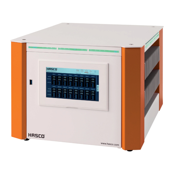
- Page 1 Operating instructions H1280/... Multi-zone control unit D / GB / F 07 / 19...
- Page 2 They must always be readily available during operation. The operating instructions form the basis for the safe handling of HASCO hot runner technology. The instructions and information given here, and particularly the safety rules, must be followed under all circumstances.
-
Page 3: Table Of Contents
Operation ........................24 5.3.2.1 Home view ......................... 24 5.3.2.1.1 General presentation ................... 24 5.3.2.1.2 Changing the setpoint value and output level ............29 5.3.2.1.3 Activating the boost function ................29 5.3.2.1.4 Changing the operating mode ................30 4 HASCO hot runner... - Page 4 Terminal bridges in star supply network (status as delivered) ........46 8.1.2 Terminal bridges in triangle supply network ..............46 Pin assignment alarm socket ....................47 Pin assignment digital input ....................47 Index of keywords........................48 HASCO hot runner 5...
-
Page 5: Introduction
To prevent any damage to the controller, it must be transported and stored in the correct manner. Further safety-related notices are marked in the individual sections of this documentation. 6 HASCO hot runner... -
Page 6: Structure And Functionality
6, 12, 18, 24 or 36 heating zones. 3.2 Structure A 12-zone controller is shown by way of example in the figures that follow. All the designated components are identical on controllers with more than 12 heating zones. Figure 1 - Housing front HASCO hot runner 7... - Page 7 (2) USB connection (3) LED strip (4) Connection line (5) Main switch (6) Plug system (example) (7) Alarm socket (8) RS485 connection (9) Ethernet connection (10) Digital input (11) Fuse (12) Status LED (13) Power board 8 HASCO hot runner...
-
Page 8: Display (1)
Chapter 8.3 shows the assignment plan for the digital inputs with the corresponding functions. The digital inputs are PLC compatible, i.e. they operate over a voltage range of 13...30 VDC with a typical current consumption of approx. 8.5 mA. HASCO hot runner 9... -
Page 9: Identification Marking On The Controller
Before working on the connected heating elements, the associated connections must be unplugged, or the entire device disconnected from the mains power. Before the device is opened, it must be disconnected from the mains power. 10 HASCO hot runner... -
Page 10: Mains Electricity
4.2.3 Operation The hot runner controller is operated exclusively via the integral 7” touch display (Figure 1) on the housing front. Please note: The cooling unit can become hot during heating. Avoid touching the heating unit. HASCO hot runner 11... -
Page 11: Start Menu
If the user does not enter anything at this point, the controller will automatically switch to the operating view after 30 seconds. Deutsch English Quick start Start Start New mould Saved settings With recipe Figure 6 - Home screen 12 HASCO hot runner... -
Page 12: Navigation Bar
This symbol is only visible if operation in the corresponding user level is blocked. Once a user level has been released with the corresponding password, the following symbol User level will appear: HASCO hot runner 13... -
Page 13: Selection Of Zones And Groups For Operation
For displaying and modifying values and displaying faults during operation. Settings For the general configuration and readout of information about the controller. Each of these three main areas is, in turn, divided into subareas that are explained in more detail below. 14 HASCO hot runner... - Page 14 Recipe Boost Device Communication Service Settings Language Device info Controller-specific Date / Time Service file User management Firmware update File management Support Figure 9 - Navigation menu HASCO hot runner 15...
-
Page 15: Setup
Setup > Quick start > Operating mode In the "Operating mode" menu item, a specific operating mode can be entered for each zone. Procedure: First select the zones on the left whose operating mode is to be changed. 16 HASCO hot runner... -
Page 16: Setpoint Values
On the right side, select one of the setpoint values described below Open the box for entering the setpoint value with Enter the desired value in the input box Confirm with OK. Value Setting limits HASCO hot runner 17... -
Page 17: Monitoring
The LED strip will light up red and the zone will 800°C sensor type Standard: temporarily turn off its output. A potential-free contact can signal this alarm to the outside. If 400 °C the actual value falls below this limit value, this alarm will automatically deactivate. 18 HASCO hot runner... -
Page 18: Sensor Fracture Monitoring
The zone reports a warning under sensor fracture and then switches level permanently to the output level that can be adjusted here. The output level can be specified after pressing the button and is displayed at the zones. HASCO hot runner 19... -
Page 19: Residual Current Monitoring
The LED strip lights up yellow and, on the touch display, the relevant Standard: 100 % zone is marked with a warning symbol A potential-free contact can signal this alarm to the outside. 20 HASCO hot runner... -
Page 20: Heating Current Monitoring
The heating behaviour of each individual zone can be selected here. Function Description Sequence in a A heating group ensures the uniform heating of all the zones. This avoids stresses in heating group the mould and premature overheating of fast individual nozzles. HASCO hot runner 21... -
Page 21: Mould Test
Symbol Meaning This zone is currently being tested. 0:25 The duration of the mould test for this zone is shown in minutes:seconds. The mould test for this zone has been successfully completed 22 HASCO hot runner... -
Page 22: Others
In the zone display, the output level will be placed in brackets once the output level limit is attained. In the following example, an output limit of 70% is shown in the zone display. Display of the output level limit: Zone 2 Output level Y is currently limited to 70%. Actual [°C] Setpoint [°C] HASCO hot runner 23... -
Page 23: Operation
Behaviour in the event of sensor fracture is depicted in the zone designation box: BSF = …. Fault icon The fault icon flashes in the zone designation box. Clicking on the fault icon will call up the diagnosis. 24 HASCO hot runner... - Page 24 The actual value display with this symbol means that no valid actual value is being measured. This symbol only occurs in combination with faults such as a sensor fracture or CAN faults. Optimised The controller automatically determines the control parameters. HASCO hot runner 25...
- Page 25 From the control quality displayed, it is possible to see how constantly the zone can maintain the setpoint value. 100% means no deviation over a fairly long period of time. Zones with process-related, short-term tolerances (friction, injection cycle) have a lower quality. 26 HASCO hot runner...
- Page 26 T [°C] value, in this case 20°. Active zone with graphic display of the control deviation. Zone 1 If the bar display of the control deviation is below the zero line, the actual value is too low. HASCO hot runner 27...
- Page 27 Zone 1 in monitoring mode with actual value and output level. Zone 1 Monitoring The output level display remains empty because no output level Actual [°C] is output in monitoring mode (outputs are switched off). Y [%] 28 HASCO hot runner...
-
Page 28: Changing The Setpoint Value And Output Level
It is thus possible to see at a glance how long the boost process still has to run. Example Boost function not activated Boost function just started. The boost function has now run for half of the boost time. HASCO hot runner 29... -
Page 29: Changing The Operating Mode
A detailed list of all the warnings and alarms is given in Chapter 5.3.2.2.4. Procedure in the event of a fault (example: “defective triac” fault message): Example 1 To the fault handling via the navigation menu 30 HASCO hot runner... -
Page 30: Warnings And Alarms
- Overfeeding - Heating unit is ageing Output level deviation - Defective parallel heating Collective warning The mean output level is above the set - Heating fault tolerance value. - Setting limit - Triac HASCO hot runner 31... - Page 31 - Insulation damage controlled Defective triac - Triac Collective alarm Current flows when the outputs are not being controlled. Relay fault - Internal hardware error Collective alarm The output relay of the relevant zone is defective. 32 HASCO hot runner...
-
Page 32: Plotter
60 min The plotter displays a time range of 60 minutes. The plotter displays a time range of 4 hours. Zoom in The plotter’s display range is reduced Zoom Out The plotter’s display range is enlarged HASCO hot runner 33... -
Page 33: Control
I component I component of the PID controller. The reset time TN of the PID controller is specified in this setting. Increasing the reset time causes a slower transient response. Setting limits: 999s Factory setting: 80s 34 HASCO hot runner... -
Page 34: Heating Signal
The procedure for changing the heating signal is as follows: First select the zones on the left whose heating signal is to be changed. Then, on the right side, select the desired heating signal Confirm with HASCO hot runner 35... -
Page 35: All Parameters
Settings Controller-specific Language Device Date / Time Service file User management Firmware update File management Support Figure 13 - Settings 5.3.3.1 Device 5.3.3.1.1 Language Settings > Device > Language 36 HASCO hot runner... -
Page 36: Temperature Unit
3. The changes can be activated by pressing the “Accept changes” button 4. X closes the dialogue. As soon as the timer is activated, an alarm clock symbol appears on the right of the menu bar next to the date and time. HASCO hot runner 37... -
Page 37: User Administration
█ Activation of standby █ Operating modes █ Parametrisation █ Mould test Setup █ Diagnosis incl. fault handling Locked: █ User administration █ Factory setting Administration No restrictions The administrator can change and delete the passwords. 38 HASCO hot runner... -
Page 38: File Management
Clicking on “Move” and “Confirm selection” will activate the move. The dialogue for selecting the target directory will appear. The target directory can be changed by pressing the arrow. After selecting the desired target HASCO hot runner 39... -
Page 39: Communication
For updates of the power boards, a USB stick with the firmware must be inserted in the main directory and the device restarted. Then follow the instructions on the starting page. Once the update process is completed, the USB stick must be removed. The controller will start again. 40 HASCO hot runner... -
Page 40: Index Of Keywords
A longer press on the arrow button will start the heating process by activating the controller outputs. Zones in the “Inactive mode” operating mode will remain switched off. When the outputs are activated, the internal relays will close and the output level will be output at the corresponding contacts. HASCO hot runner 41... -
Page 41: Standby Operation
During standby, the pause button changes and is displayed with a coloured background. If the pause button is pressed again, standby mode will be cancelled and the pause button will appear in its non-activated presentation again with a white background. 42 HASCO hot runner... -
Page 42: Technical Data
Alarm notification outputs 3x relay contact Potential-free for max. 250 VAC Maximum current 4 A for cos = 1; 2A for cos = 0.5 Digital inputs Insulated, potential-free 16 – 30 V DC Data interfaces Ethernet CAT 5 HASCO hot runner 43... -
Page 43: Dimensions
RS485 D-SUB 9-pole USB 3.0 Standard 7 Dimensions 7.1 12-zone controller 7.2 24-zone controller 44 HASCO hot runner... -
Page 44: 36-Zone Controller
Bedienungsanleitung H1280 7.3 36-zone controller HASCO hot runner 45... -
Page 45: Appendix
8.1 Terminal bridges for the star-delta supply 8.1.1 Terminal bridges in star supply network (status as delivered) Figure 14 - Star supply network 8.1.2 Terminal bridges in triangle supply network Figure 15 – Triangle supply network 46 HASCO hot runner... -
Page 46: Pin Assignment Alarm Socket
Collective alarm Opener 2 + 6 Unused contact Opener 8.3 Pin assignment digital input Table 2 Function Digital input 1 – 3 No function Standby +24V No function 6 – 8 9 – 15 No function HASCO hot runner 47... -
Page 47: Index Of Keywords
Output level limited ................................27 P component ................................... 40 Parameters ..................................42 Password ..................................46 Plotter ..................................... 39 Positive temperature deviation ............................36 Power board ..................................10 Quick start ................................. 14, 18 Ramp gradient ................................25 Recipe ..................................14, 42 48 HASCO hot runner... - Page 48 Timer ....................................44 Tolerance range ................................21 Triangle supply network ..............................55 Type plate ..................................11 Update .................................... 49 USB connection ................................11 User administration ................................. 45 User level ..................................45 Warnings ..................................36 Zone inactive ................................... 19 HASCO hot runner 49...
- Page 49 ©by HASCOHasencleverGmbH+ Co KG Postfach 1720 · D-58467 Lüdenscheid · Tel. +49 (0) 2351 957-0 · Fax +49 (0) 2351 957-237 info@hasco.com · www.hasco.com Subject to technical modifications. Please always check all the data against the product information we publish in the internet. HASCO hot runner 50...
- Page 50 Built to run. www.hasco.com...
Need help?
Do you have a question about the H1280 Series and is the answer not in the manual?
Questions and answers