
Related Manuals for ABB GSBK Series


Summary of Contents for ABB GSBK Series
- Page 1 1ZSC000563-AAB EN, REV. 6, 2019-09-12 Transformer bushing, type GSBK Installation and maintenance guide...
- Page 2 The information contained in this document may be subject to change without prior warning and should not be considered as binding on ABB AB’s behalf. ABB AB accepts no liability for any errors that may appear in this document. ABB AB is not liable for any damage resulting from the incorrect interpretation of this document.
-
Page 3: Table Of Contents
Contents Safety Levels of safety risks ................................... 5 Hazardous working situations ..............................6 Safety precautions..................................6 Product description Design ......................................7 Transformer testing ..................................10 Technical specifications ................................11 2.3.1 General specifications ............................... 11 2.3.2 Mechanical loading..............................12 Delivery Incoming inspection.................................. - Page 4 Maintenance Recommended maintenance ..............................53 Re-packing Removal of the bushing from the transformer, fixed bottom contact ................... 55 Removal of the bushing from the transformer, draw rod ......................56 Re-packing of the bushing................................60 Spare parts Summary ..................................... 63 Spare parts ....................................
-
Page 5: Safety
1 Safety 1.1 Levels of safety risks Throughout the manual, various types of safety risks are indicated. The most serious level on this scale provides a warning about serious personal injury or possible death, or major damage to a product, if the instructions are not observed. -
Page 6: Hazardous Working Situations
1.2 Hazardous working situations Hazard Action Working close to high voltage. Disconnect all plant power. Ground all objects at the workplace. If work must be done close to live plant components, make sure that the safety distance is in compliance with the applicable safety regulations. -
Page 7: Product Description
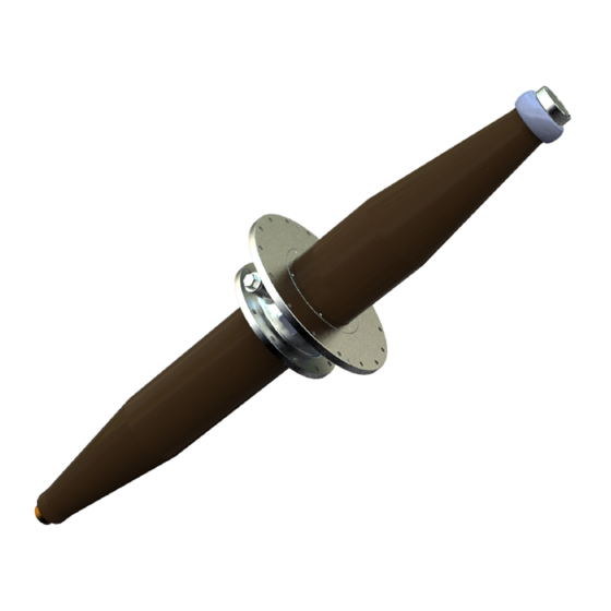
2 Product description 2.1 Design Overview The GSBK type is a transformer bushing. It is made for immersed oil to SF service. The bushing is of the dry, gas-free type, with a resin impregnated paper RIP condenser core as the primary insulation. Bushings of this design can be installed at any angle from vertical to horizontal. - Page 8 Terminal system The bushing can be configured with one of two terminal systems: the fixed bottom contact system, or the draw-rod system. Draw rod Fixed bottom contact Installation and maintenance guide 1ZSC000563-AAB EN, REV. 6, 2019-09-12...
- Page 9 Test tap The bushing has a test tap that is connected to the outermost conductive layer of the condenser core. The test tap is used to measure the bushing insulation by capacitance and dissipation factor. The cover connects the outermost conductive layer to ground, and must always be installed when the bushing is energized. The maximum one minute test voltage for this test tap is 2 kV .
-
Page 10: Transformer Testing
Voltage tap The voltage tap is available as an option, instead of the test tap. The bushing has a voltage tap that is connected to the second outermost conductive layer of the condenser core. The voltage tap is used to measure the bushing insulation by capacitance and dissipation factor. The cover connects the outermost conductive layer to ground, and must always be installed when the bushing is energized. -
Page 11: Technical Specifications
2.3 Technical specifications 2.3.1 General specifications Refer to the table for the standard technical specifications of the bushing. For conditions exceeding the specifications, please contact ABB. Application: Transformers Classification: Tranformer bushing • Resin impregnated paper, capacitance graded, oil immersed. •... -
Page 12: Mechanical Loading
The bushing can be installed in all positions from horizontal to vertical. NOTE! The loads described in this section are static loads, for dynamic loads such as earthquakes and extreme wheather conditions, please contact your ABB sales representative. Installation and maintenance guide 1ZSC000563-AAB EN, REV. 6, 2019-09-12... - Page 13 Load on the outer terminal Cantilever load Outer terminal Type Maximum cantilever load on the outer terminal: Type test load, 1 minute (kN) Maximum service load (kN) GSBK 170 GSBK 245 GSBK 362 GSBK 420 GSBK 550 Installation and maintenance guide 1ZSC000563-AAB EN, REV.
- Page 14 Load on the bushing flange Bending moment Compressive or tensile load Shearing load Bushing flange Type Maximum bending moment on the Maximum load on the bushing flange in bushing flange: service: Test load (kNm) In operation (kNm) Shearing load (kN) Compressive or tensile load (kN) GSBK 170 GSBK 245...
-
Page 15: Delivery
3 Delivery 3.1 Incoming inspection • Make sure that all items have been delivered, refer to the packing list. • Carefully inspect the bushings for shipping damage. 3.2 Transportation • The bushing must be transported in the transport box. • Make sure that the bushing is wrapped in the original (or equivalent) moisture proof wrapping. -
Page 16: Lifting
• The bushing can be stored in both the vertical, and horizontal positions. The bushing is delivered from ABB in a transport box, and the bushing is held in place by support blocks and fiberboard in the box. 3.4 Lifting 3.4.1 Lifting the transport box... -
Page 17: Lifting The Bushing Out Of The Transport Box
Procedure Make sure that the crane and the soft lifting slings are approved for the total weight of the transport box and bushing. Refer to the weight in the packing list. Attach soft lifting slings (2). Make sure that the angle of the soft lifting sling is not more than 20°. Carefully lift the transport box. - Page 18 Attach a soft lifting sling to the condenser core (1) and then to the crane hook. Attach a soft lifting sling to the condenser core (1) and then to the crane hook. Carefully lift the bushing. Lower the bushing onto soft bedding. End of instruction Installation and maintenance guide 1ZSC000563-AAB EN, REV.
-
Page 19: Installation
For removal, and installation of the bottom contact. Draw-rod system. Tackle For installation of the bushing at a specific angle. 4.2 Consumables Item Brand ABB part Note number Oil based Vaseline Fuchs 1171 5011-102 For treatment of contact surfases. Does not react with transformer oil. -
Page 20: Installation With Fixed Bottom Contact
4.3 Installation with fixed bottom contact 4.3.1 Installation of lifting tools Overview Soft bedding, i.e. rubber mat or woodboard Lifting eye Procedure Install the lifting eyes (1) in the top end and intermediate flange. Installation and maintenance guide 1ZSC000563-AAB EN, REV. 6, 2019-09-12... - Page 21 Attach soft lifting slings (8) from the lifting eye to the crane hook. For installation at a specific angle: attach soft lifting slings with a schackle (9) from the intermediate flange to the crane hook. End of instruction Installation and maintenance guide 1ZSC000563-AAB EN, REV.
-
Page 22: Installation With Fixed Bottom Contact
4.3.2 Installation with fixed bottom contact Bottom contact Bushing Pulling ring Procedure If the bushing has the optional transport container installed, remove it. CAUTION! Do not cause damage to the RIP-core when removing the transport container. Installation and maintenance guide 1ZSC000563-AAB EN, REV. - Page 23 Make sure that there is a distance of 7 ±0.5 mm between the pressing ring (17) and the pulling ring (3). Make sure with a torque wrench that the the six bolts are tightened with a torque of 40 Nm. Torque 40 Nm Make sure that the gasket is installed in the turret...
- Page 24 Lower the bushing onto the transformer. When installing the bushing at the transformer factory: Make sure that the bushing is installed in the correct orientation. Make permanent markings (16) on the bushing flange and the transformer turret. Install the bolts and washers. Tighten the bolts in a crosswise sequence.
- Page 25 Remove the lifting eyes (1). Put the winding cables through the end-shield. Install the winding cables to the bottom contact. CAUTION! Make sure that there is no tension in the winding cables. Tension in the winding cables will cause damage to the bottom contact.
- Page 26 Install the end shield: Push the end shield carefully against the pressing ring (17). Turn the end shield approximately 20°, to its locked position. If the transformer will be oil-filled with the atmospheric process: Remove the hex screws (6). Put the blades of two screwdrivers in the recesses (19) in the outer terminal (5), and carefully push them down to lift the outer terminal (5) straight up.
-
Page 27: Preparations With Draw Rod
4.4 Preparations with draw rod 4.4.1 Removal of the outer terminal Procedure If the bushing has the optional transport container installed, remove it. CAUTION! Do not cause damage to the RIP-core when removing the transport container. Remove the hex screws (6). Put the blades of two screwdrivers in the recesses (19) in the outer terminal (5), and carefully push them down to lift the outer terminal (5) straight up. -
Page 28: Removal Of The Lower Draw Rod With Bottom Contact From The Bushing
4.4.2 Removal of the lower draw rod with bottom contact from the bushing Overview The bottom contact is usually installed in the bushing when it is delivered from ABB, the first step at the transformer factory is thus to remove it. - Page 29 Procedure If the bushing has the optional transport container installed, remove it. CAUTION! Do not cause damage to the RIP-core when removing the transport container. Put the pull-through cord (12) through the box-spanner (13). NOTE! The terminal on the pull-through cord (12) has M8 threads.
-
Page 30: Installation Of The Large Bottom Contact In The Transformer
Remove the M16 nut (10) and washer (11), on the draw rod with the box spanner. CAUTION! Do not remove the compensation device. NOTE! Keep the draw-rod nut (10) and washer (11), they will be used again. Pull down the draw rod from the bottom end of the bushing, and disassemble it at the lower joint (8). - Page 31 Procedure Remove the transformer cover (13) from the transformer turret (11). Install the winding cables to the bottom contact. CAUTION! Make sure that there is no tension in the winding cables. Tension in the winding cables will cause damage to the bottom contact.
-
Page 32: Lifting The Bushing For Installation On The Transformer
4.4.4 Lifting the bushing for installation on the transformer Procedure Make sure that the crane can lift the bushing. Refer to the net weight in the packing list. Align the crane hook with the lifting tool on the bushing. Attach soft lifting slings (8) to the lifting tool and to the crane hook. -
Page 33: Installation With Draw Rod
Align the bushing with the hole in the transformer turret. End of instruction 4.5 Installation with draw rod 4.5.1 Installation of the bushing on the transformer Overview Draw-rod Pull-through cord Installation and maintenance guide 1ZSC000563-AAB EN, REV. 6, 2019-09-12... - Page 34 Procedure Connect the upper draw-rod (1) to the lower draw-rod (4). Hold the pull-through cord (12) in tension, while lowering the bushing onto the transformer. CAUTION! Do not damage the stud bolts. There is a risk of metal falling into the transformer.
- Page 35 Install the bolts and washers. Tighten the bolts in a crosswise sequence. • When installing the bushing at site, make sure that the marking (16) on the bushing flange lines up with the marking on the transformer turret. Torque Refer to the transformer manufacturers documentation.
-
Page 36: Manual Tightening Of The Draw-Rod Nut
Remove the lifting eyes (1). Tighten the draw-rod nut, refer to Hydraulic tightening of the draw-rod nut, page 38, or Manual tightening of the draw-rod nut, page 36. End of instruction 4.5.2 Manual tightening of the draw-rod nut Overview This procedure requires the draw-rod nut, washer and threads of the draw rod to be correctly lubricated. The draw rod will not get the correct tension if the fasteners are not correctly lubricated, this can cause the bushing to fail. - Page 37 Turn the nut clockwise until you get the the correct extension (b). Distance (b) = (a) + extension, refer to the table. CAUTION! Make sure that you do not overtighten the nut. Use a torque wrench set to 140 Nm. NOTE! One turn of the nut corresponds to a 2 mm extension of the draw rod.
-
Page 38: Hydraulic Tightening Of The Draw-Rod Nut
4.5.3 Hydraulic tightening of the draw-rod nut Overview Hydraulic jack Draw-rod nut Procedure Install the hydraulic jack (8). Pull the draw rod with a force according to the table. Type Force CT 300 mm CT 600 mm GSBK 170 39.5 kN 39.5 kN GSBK 245 39.1 kN... -
Page 39: Oil-Filling
4.6 Oil-filling Overview Start this procedure when the transformer oil has reached the bottom of the bushing. • This procedure is NOT applicable if the transformer is oil-filled with the vacuum process. The purpose of this procedure is to remove as much air as possible from the center tube of the bushing. Because air is soluble in transformer oil, air will go into the transformer oil and will cause its performance to deteriorate. -
Page 40: Installation Of The Outer Terminal
Wait until the oil-level (h) in the center-tube has risen to the same height as the oil-level in the transformers oil-conservator. • If the top of the bushing is lower than the transformers oil-conservator, wait until oil flows out from top of the bushing. NOTE! Air is soluble in transformer oil, thus as much as possible must be released... - Page 41 Carefully clean the contact and gasket surfaces with a soft cloth, and then apply Mobilgrease 28 to the contact surfaces and the O-rings (3). CAUTION! Do not use a wire brush on aluminium outer terminals. A wire brush can make scratches in the silver coating.
- Page 42 Apply Mobilgrease 28 to the M10 hex screws (6). NOTE! Or use Molykote 1000 as an alternative. Install the M10 hex screws (6). Tighten the M10 hex screws (6) in a crosswise sequence. CAUTION! Make sure that the outer terminal moves straight down.
- Page 43 Prepare the contact surface of the outer terminal for the external connection. Refer to the documentation from the supplier of the external connection. Install the external connections. Refer to the documentation from the supplier of the external connection. End of instruction Installation and maintenance guide 1ZSC000563-AAB EN, REV.
-
Page 44: Grounding Of The Bushing Flange
4.8 Grounding of the bushing flange Overview The bushing flange must be grounded to the transformer tank. This prevents electrical discharge between the bushing flange and the transformer tank under normal service conditions. There are two alternatives. DANGER! Make sure that the grounding is correct. An unsatisfactory grounding can cause damage to equipment, or death to personnel. - Page 45 Procedure with a flexible cable Clean the contact surfaces. Put a flexible cable (14) between the grounding hole in the bushing flange and a grounding point on the transformer. Apply a large quantity of Mobilgrease 28 to the bolt (13). CAUTION! The quality of the bolt is important, stainless steel of A4-80 quality is recommended.
- Page 46 Installation and maintenance guide 1ZSC000563-AAB EN, REV. 6, 2019-09-12...
-
Page 47: Commissioning
5 Commissioning 5.1 Waiting time before energization Waiting times after oil-filling of the transformer Some waiting time is necessary after the transformer has been oil-filled, before the bushing is energized. The reason for this is that air bubbles stick to the bushings surface when the transformer is filled with oil, and flashovers and partial discharges can form in the bubbles. -
Page 48: Measurement Of Capacitance And Dissipation Factor
5.2.3 Measurement of capacitance and dissipation factor Overview After installation of the bushing, it is recommended to measure the capacitance values for future reference, such as repairs, service etc. This can be done on an installed bushing because it has an insulated test/voltage tap. - Page 49 Dissipation factor, tan δ The dissipation factor varies with the temperature of the bushing core, and thus the measured dissipation factor must be multiplied with the correction factor given below. Bushing core temperature °C Correction factor to 20 °C (IEC) 0.76 0.81 8-12...
- Page 50 Connect the measuring equipment. Connect the low voltage cable to the stud (1). Connect the high voltage cable to the outer terminal. Connect the ground cable to the bushing flange (3). Measure the capacitance (C ) between the outer terminal and the stud (1). •...
-
Page 51: Measurement Of Through-Resistance
Connect the outer terminal of the bushing to the external connections. End of instruction 5.2.4 Measurement of through-resistance Overview The method to use for measuring the through-resistance depends on the design of the transformer. In general, a current is applied from bushing to bushing. The voltage drop from the outer terminal to outer terminal is measured. - Page 52 Installation and maintenance guide 1ZSC000563-AAB EN, REV. 6, 2019-09-12...
-
Page 53: Maintenance
Make a visual inspection for oil leakage during regular station supervision. After repairs ABB recommends that the capacitance is measured after repairs have been done, after maintenance of connected equipment, or after work near the bushing is completed. It is important to compare the capacitance before energization with the capacitance that was measured at commisioning. - Page 54 Installation and maintenance guide 1ZSC000563-AAB EN, REV. 6, 2019-09-12...
-
Page 55: Re-Packing
7 Re-packing 7.1 Removal of the bushing from the transformer, fixed bottom contact Procedure Install the lifting tool, refer to Installation of lifting tools, page 20. Remove the end shield: Push the end shield carefully against the pressing ring (17). Turn the end shield approximately 20°, and lower it. -
Page 56: Removal Of The Bushing From The Transformer, Draw Rod
Remove the bolts and washers. Carefully lift the bushing from the transformer. CAUTION! Do not cause damage to the stud bolts, there is a risk of metal falling into the transformer. Install the transport cover (13) on the transformer turret (11). Lower the bushing to the floor. - Page 57 Put the pull-through cord (12) through the box-spanner (13). NOTE! The terminal on the pull-through cord (12) has M8 threads. Apply Vaseline to the thread on the pull-through cord (12), then connect it to the draw rod. NOTE! Or use a lubricant with equal properties to Vaseline.
- Page 58 Remove the bolts and washers. Hold the pull-through cord (12) in tension, while lifting the bushing from the transformer. CAUTION! Do not damage the stud bolts, there is a risk of metal falling into the transformer. Disassemble the draw rod at the lower joint (8). Use the key grip on the lower draw rod.
- Page 59 Pull up the draw rod, and install the washer (11) and nut (10). CAUTION! Make sure that the centering ring (28) is in position, it is necessary for the correct installation of the draw rod. Remove the pull-through cord. Lower the bushing to the floor. CAUTION! Make sure that there is soft bedding, or support blocks on the floor.
-
Page 60: Re-Packing Of The Bushing
7.3 Re-packing of the bushing Overview Procedure For storage <6 months: wrap the bushing in the original protective wrapping, and replace the drying agent. For storage >6 months: install the transport container (1): Replace the drying agent in the transport container (1). - Page 61 Lower the bushing into the transport box. CAUTION! Make sure that the support blocks are in the correct positions in the transport box. Make sure that the there is soft bedding in the transport box. CAUTION! Make sure that the test/voltage tap does not make contact with the transport box, or other objects.
- Page 62 Installation and maintenance guide 1ZSC000563-AAB EN, REV. 6, 2019-09-12...
-
Page 63: Spare Parts
8 Spare parts 8.1 Summary If the bushing is damaged, we recommend that it is returned to ABB for repairs and re-testing. Some parts that are damaged or lost during transportation or installation can be ordered from ABB. 8.2 Spare parts Cover For the test/voltage tap. -
Page 64: Special Tools
8.3 Special tools Lifting tool Part Article number Note Lifiting eye 9ADA338 2 pcs. Pull-through cord Part Article number Note Pull-through cord 9760 669-A With M8-terminal. Installation and maintenance guide 1ZSC000563-AAB EN, REV. 6, 2019-09-12... - Page 65 Hydraulic jack Part Article number Note Hydraulic jack 2769 897-A For removal, and installation of the bottom contact. Draw-rod system. Box-spanner Part Article number Note Box-spanner 9760 669-B Installation and maintenance guide 1ZSC000563-AAB EN, REV. 6, 2019-09-12...
- Page 66 Installation and maintenance guide 1ZSC000563-AAB EN, REV. 6, 2019-09-12...
-
Page 67: Disposal And Environmental Information
9.2 Disposal and recycling ABB strives to minimize the product's impact on the environment throughout its entire life cycle. Technical and product development focuses on environmental aspects. The ecocycle approach is striven for, and consideration is taken to the materials' environmental impact and recycling alternatives. - Page 68 As an alternative, the gas mixture can be sent for destruction without being separated. Upon request, ABB can provide a quote for final disposal of used gas in connection with the disposal of a bushing.
-
Page 69: Reference
10 Reference 10.1 Summary • Markings: Conforming to IEC/IEEE. • Bushing diagnostics and conditioning, 2750 515-142. • The quality of the SF gas must comply with standard IEC 60376. Installation and maintenance guide 1ZSC000563-AAB EN, REV. 6, 2019-09-12... - Page 72 ABB AB, Components SE-771 80 Ludvika, Sweden www.abb.com/transformercomponents © Copyright 2019 ABB, All rights reserved. Specifications subject to change without notice.