Table of Contents
Advertisement
GB75-1.7
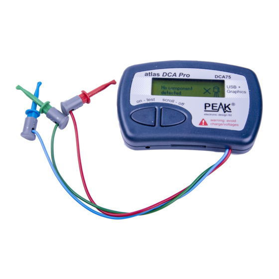
Peak Atlas DCA Pro
Advanced Semiconductor Component Analyser
with Graphics Display and PC connectivity
Model DCA75
Designed and manufactured with pride in the UK
User Guide
©
Peak Electronic Design Limited 2012/2019
In the interests of development, information in this guide is subject to change without notice - E&OE
Advertisement
Table of Contents

Related Manuals for Peak Atlas DCA75 Pro


Summary of Contents for Peak Atlas DCA75 Pro
- Page 1 Graphics Display and PC connectivity Model DCA75 Designed and manufactured with pride in the UK User Guide © Peak Electronic Design Limited 2012/2019 In the interests of development, information in this guide is subject to change without notice - E&OE...
-
Page 2: Table Of Contents
June 2019 – Rev 1.7 Want to use it now? We understand that you want to use your Peak Atlas DCA Pro right now. The unit is ready to go and you should have little need to refer to this user guide, but please make sure that you do at least take a look at the notices on page 5. - Page 3 PC mode - Exporting your data..........36 PC mode - Special functions ..........37 Audible Settings ................38 Care of your Peak Atlas DCA Pro..........39 Appendix A - Troubleshooting............. 40 Appendix B - General Technical Specifications ......41 Appendix C - Component Testing Specifications ......42 Appendix D - Analysis test circuits..........
-
Page 4: Introduction
June 2019 – Rev 1.7 Introduction The Peak Atlas DCA Pro is an advanced semiconductor analyser that combines simplicity, ease of use and a range of advanced features. You can use your DCA Pro on its own or in combination with a laptop or desktop PC. -
Page 5: Important Considerations
Peak Atlas DCA Pro User Guide June 2019 – Rev 1.7 Important Considerations Please observe the following guidelines: This instrument must NEVER be connected to powered • equipment/components or equipment/components with any stored energy (e.g. charged capacitors). Failure to comply with... -
Page 6: Analysing Semiconductors - Standalone Mode
Peak Atlas DCA Pro User Guide June 2019 – Rev 1.7 Analysing Semiconductors – Standalone mode The DCA Pro is designed to analyse discrete, unconnected, unpowered components. This ensures that external connections don’t influence the measured parameters. The three test probes can be connected to the component any way round. - Page 7 Peak Atlas DCA Pro User Guide June 2019 – Rev 1.7 If the DCA Pro cannot detect any supported component between any of the test probes, the following message will be displayed: If the component is not a supported component type, a faulty component or...
-
Page 8: Diodes
Peak Atlas DCA Pro User Guide June 2019 – Rev 1.7 Diodes The DCA Pro will analyse almost any type of diode. Any ode. Any pair of the three test clips can be connected to the diode, any way he diode, any way round. -
Page 9: Zener Diodes
Peak Atlas DCA Pro User Guide June 2019 – Rev 1.7 Zener Diodes The DCA Pro supports Zener diodes (and Avalanche Avalanche diodes). Additionally, the instrument can measure the Zener easure the Zener voltage*. Connect any pair of the 3 test leads to the Zener diode. Following analysis, the component details are displayed. -
Page 10: Diode Networks
SOT-23 diode networks, all three test clips must be connected. The optional Peak Component Adapter for SOT-23 parts (Peak model PCA23) can be useful for testing SOT-23 parts. The instrument will describe the type of diode network as text and as a component schematic symbol. -
Page 11: Leds
Peak Atlas DCA Pro User Guide June 2019 – Rev 1.7 LEDs An LED (light emitting diode) is really just another type of diode, however, the DCA Pro will determine that an LED or LED network has been detected if the diode’s measured forward voltage drop is p is between 1.5V and 4.0V. -
Page 12: Bicolour Leds (2-Lead Types)
Peak Atlas DCA Pro User Guide June 2019 – Rev 1.7 Bicolour LEDs (2-lead types) Bicolour LEDs are generally available in two main varieties; 2-lead and 3-lead types. This section describes the testing of 2-lead bicolour olour LEDs. These types are internally connected in inverse-parallel (back-to-back). -
Page 13: Bicolour Leds (3-Lead Types)
Peak Atlas DCA Pro User Guide June 2019 – Rev 1.7 Bicolour LEDs (3-lead types) 3-lead bicolour LEDs are available in common cathode common anode varieties. The DCA Pro supports both types. In the same way as the 2-lead bicolour LED analysis, each internal LED is detailed separately on the DCA Pro screen. -
Page 14: Bipolar Junction Transistors (Bjts)
Peak Atlas DCA Pro User Guide June 2019 – Rev 1.7 Bipolar Junction Transistors (BJTs) Bipolar Junction Transistors are simply “conventional” transistors, although variants of these do exist such as Darlingtons, devices with free-wheeling diodes, resistor shunted types and combinations of these types. All of these variations are automatically identified by the DCA Pro and their schematic symbol is displayed on the screen. - Page 15 Peak Atlas DCA Pro User Guide June 2019 – Rev 1.7 Current Gain (h DC current gain (h ) is the ratio of the collector current (less leakage) to the base current for a particular operating condition. The DCA Pro measures h at a collector current of nominally 5.0mA and a...
- Page 16 Peak Atlas DCA Pro User Guide June 2019 – Rev 1.7 Base-Emitter Voltage Drop The DC characteristics of the base-emitter junction are displayed, both the base-emitter forward voltage drop (V ) and the base current (I ) used for that measurement.
- Page 17 Peak Atlas DCA Pro User Guide June 2019 – Rev 1.7 Collector Leakage Current The collector current that takes place when no base current is flowing is referred to as Leakage Current. Most modern transistors exhibit extremely low values of leakage current, even for very high collector-emitter voltages.
-
Page 18: Darlington Transistors
Peak Atlas DCA Pro User Guide June 2019 – Rev 1.7 Darlington Transistors If the device is a Darlington transistor (two BJTs connected together), the unit will display a similar message to this: Darlington devices that do not have internal resistors can exhibit very high... - Page 19 Peak Atlas DCA Pro User Guide June 2019 – Rev 1.7 Free Wheeling Diode Some transistors, particularly CRT deflection transistors and many large Darlingtons have a protection diode (“free wheeling diode” or “body diode”) inside their package connected between the collector and emitter.
- Page 20 Peak Atlas DCA Pro User Guide June 2019 – Rev 1.7 Faulty or Very Low Gain Transistors Faulty transistors that exhibit very low gain may cause the DCA Pro to only identify one or more diode junctions within the device. This is...
-
Page 21: Digital Transistors
Peak Atlas DCA Pro User Guide June 2019 – Rev 1.7 Digital transistors Digital transistors aren’t really digital, they can act in both a linear or fully on/off mode. They’re called “digital transistors” because they can be driven directly by digital outputs without the need for base current limiting resistors. -
Page 22: Enhancement Mode Mosfets
Peak Atlas DCA Pro User Guide June 2019 – Rev 1.7 Enhancement Mode MOSFETs MOSFET stands for Metal Oxide Semiconductor Field Effect Transistor. They are available in two main types, N-Channel and P-Channel. Most modern MOSFETs are of the Enhancement Mode type, meaning that the bias of the gate-source voltage is always positive (For N-Channel types). -
Page 23: Depletion Mode Mosfets
Peak Atlas DCA Pro User Guide June 2019 – Rev 1.7 Depletion Mode MOSFETs The fairly rare Depletion Mode MOSFET is very similar to the conventional Junction FET (JFET) except that the gate terminal is insulated from the other two terminals. The input resistance of these devices can typically be greater than 1000MΩ... -
Page 24: Enhancement Mode Igbts
Peak Atlas DCA Pro User Guide June 2019 – Rev 1.7 Enhancement Mode IGBTs IGBT is an acronym for Insulated Gate Bipolar Transistor. It combines the input characteristics of a MOSFET with the output characteristics of a Bipolar Junction Transistor. -
Page 25: Depletion Mode Igbts
Peak Atlas DCA Pro User Guide June 2019 – Rev 1.7 Depletion Mode IGBTs Like MOSFETs, IGBTs are available as enhancement mode and depletion mode types. Depletion mode IGBTs are characterised by the fact that current can flow between the collector and emitter when there is zero voltage across the gate-emitter terminals. -
Page 26: Junction Fets (Jfets)
Peak Atlas DCA Pro User Guide June 2019 – Rev 1.7 Junction FETs (JFETs) Junction FETs are conventional Field Effect Transistors. Here we refer to them as JFETs. The voltage applied across the gate-source terminals controls current between the drain and source terminals. N-Channel JFETs require a negative voltage on their gate with respect to their source, the more negative the voltage, the less current can flow between the drain and source. - Page 27 Peak Atlas DCA Pro User Guide June 2019 – Rev 1.7 “On” Characteristics The DCA Pro measures the gate-source voltage required to reach the onset of good conduction through the JFET’s drain-source. Good conduction is determined when the drain-source current reaches 5mA.
-
Page 28: Thyristors (Scrs) And Triacs
Peak Atlas DCA Pro User Guide June 2019 – Rev 1.7 Thyristors (SCRs) and Triacs Sensitive low power thyristors (Silicon Controlled Rectifiers - SCRs) and triacs that require gate currents and holding currents of less than 10mA can be identified and analysed with the DCA Pro. -
Page 29: Voltage Regulators
Peak Atlas DCA Pro User Guide June 2019 – Rev 1.7 Voltage Regulators The DCA Pro is able to identify many types of regulator, typically regulators with outputs less than 8V, depending on current requirements. When a regulator is identified, its pinout, output voltage, quiescent current consumption and drop-out voltage are displayed. -
Page 30: Pc Software Installation
Peak Atlas DCA Pro User Guide June 2019 – Rev 1.7 PC Software Installation The DCA Pro can be used in conjunction with a PC running Windows XP or later.* Software is provided on the included USB flash drive. Alternatively, you can download the... -
Page 31: Windows Xp Installation
Make sure the box “Include this location in the search” is checked. It should already be filled with the location for the Peak Driver. Then click Next. 6. Your DCA Pro should chime when your software is ready to use. -
Page 32: Windows Vista, 7, 8 And 10 Installation
Peak Atlas DCA Pro User Guide June 2019 – Rev 1.7 Windows Vista, 7, 8 and 10 Installation 1. Make sure you have the latest Windows Updates and Service Pack. 2. Run “Setup.exe” on the supplied USB flash drive. Alternatively, you can download and run installation file from our web site: www.peakelec.co.uk/downloads/dcaprosetup.exe... -
Page 33: Running The Dca Pro Software For The First Time
All Windows Versions Double click on the desktop icon. Click on the “DCA Pro” item in the “Peak” folder of your start menu. Windows Vista, 7, 8 & 10 (Desktop mode) Type “DCA Pro” into your start menu search box. -
Page 34: Analysing Semiconductors - Pc Mode
Peak Atlas DCA Pro User Guide June 2019 – Rev 1.7 Analysing Semiconductors – PC mode When the DCA Pro is connected to the PC and the PC is running the companion software, the instrument can be used from the PC screen or from the instrument itself. -
Page 35: Pc Mode - Curve Tracing Functions
Peak Atlas DCA Pro User Guide June 2019 – Rev 1.7 Curve Tracing After a component has been analysed, you can perform further tests on the component, such as curve tracing various component parameters. Curve tracing is best performed after the DCA Pro has correctly identified the component and correctly identified the pinout. -
Page 36: Pc Mode - Exporting Your Data
Peak Atlas DCA Pro User Guide June 2019 – Rev 1.7 Curve Tracing – Export Raw Data After the curve tracing operation has completed, you can copy the raw measurement data into the clipboard ready to be pasted into your spreadsheet program. -
Page 37: Pc Mode - Special Functions
If the firmware upgrade process fails, don’t panic, just try again, it should be fine once Windows gets its built-in driver initialised. Peak guarantee to help you if you have any problems with upgrading using our official firmware. -
Page 38: Audible Settings
Peak Atlas DCA Pro User Guide June 2019 – Rev 1.7 Audible Settings Your DCA Pro has a built-in sounder for alerting you to various test results and conditions. Additionally, the sounder produces short tones to reinforce the tactile feedback when pressing buttons. -
Page 39: Care Of Your Peak Atlas Dca Pro
Peak Atlas DCA Pro User Guide June 2019 – Rev 1.7 Care of your Peak Atlas DCA Pro Your DCA Pro should provide many years of service if used in accordance with this user guide. Care should be taken not to expose your unit to excessive heat, shock, moisture or electrical abuse. -
Page 40: Appendix A - Troubleshooting
Peak Atlas DCA Pro User Guide June 2019 – Rev 1.7 Appendix A – Troubleshooting First thing to do: It is important that you ensure you’ve got the latest version of firmware (software that’s inside the DCA Pro instrument) and the latest version of PC software. -
Page 41: Appendix B - General Technical Specifications
Peak Atlas DCA Pro User Guide June 2019 – Rev 1.7 Appendix B – General Technical Specifications Parameter Units Notes Voltage Measurement (-12V to +12V) Resolution 14.7 Accuracy ±1.2% ±15mV Voltage Drive (-12V to +12V) Resolution 18.3 Accuracy ±1.2% ±19mV... -
Page 42: Appendix C - Component Testing Specifications
Peak Atlas DCA Pro User Guide June 2019 – Rev 1.7 Appendix C – Component Testing Specifications Parameter Units Notes Bipolar Transistors Measurable current gain (h FE ) range 32000 h FE accuracy (h FE <2000) ±3% ±5 h FE... - Page 43 Peak Atlas DCA Pro User Guide June 2019 – Rev 1.7 Specifications continued... Parameter Units Notes JFETs Pinch-off V GS(OFF) range Drain current at Pinch-off 10.0 Drain current at V GS(ON) 4.75 5.00 5.25 Drain-source voltage at V GS(ON) V DS for I DSS measurement 3.25...
-
Page 44: Appendix D - Analysis Test Circuits
Peak Atlas DCA Pro User Guide June 2019 – Rev 1.7 Appendix D – Analysis Test Circuits The DCA Pro analyses components by applying signals to the component under test while in a “test circuit”. The test circuits that the DCA Pro uses to analyse various components are shown below. -
Page 45: Jfet/Mosfet/Igbt Test Circuit
Peak Atlas DCA Pro User Guide June 2019 – Rev 1.7 JFET/MOSFET/IGBT Test Circuit It’s important to note that the gate-source voltage can be driven negative by making the source voltage drive higher than the gate voltage drive. When this is done however, there is less voltage available to be across the drain-source nodes and the load resistor. -
Page 46: Diode Test Circuit
Peak Atlas DCA Pro User Guide June 2019 – Rev 1.7 Diode Test Circuit This test circuit is used for testing both the forward and reverse characteristics of diodes. Reverse characteristics are particularly useful for the testing of Zener diodes. -
Page 47: Voltage Regulator Test Circuit
Peak Atlas DCA Pro User Guide June 2019 – Rev 1.7 Voltage Regulator Test Circuit The test circuit shown here is used for the analysis of voltage regulators (positive regulators in this example). Note that the range of regulator voltages supported will depend on the quiescent current (I A higher quiescent current will cause more voltage to be dropped across the sense resistor and yield less voltage for the regulator itself. -
Page 48: Appendix E - Warranty Information
WEEE recycling agency. If in doubt, you may send your Peak Product to us for safe and environmentally responsible disposal. At Peak Electronic Design Ltd we are committed to continual product development and improvement. The specifications of our products are therefore subject to change without notice.
Need help?
Do you have a question about the Atlas DCA75 Pro and is the answer not in the manual?
Questions and answers