ABB MicroFlex e190 User Manual
Hide thumbs
Also See for MicroFlex e190:
- Quick installation manual (93 pages) ,
- Quick installation manual (21 pages) ,
- Quick installation manual (21 pages)
Table of Contents
Advertisement
Advertisement
Table of Contents

Related Manuals for ABB MicroFlex e190


Summary of Contents for ABB MicroFlex e190
- Page 1 ABB motion control User’s manual MicroFlex e190 servo drive...
- Page 2 Document library on the Internet on the inside of the back cover. For manuals not available in the Document library, contact your local ABB representative. Firmware build version that supports the option card: MicroFlex e190 Build 5900.4.0 and later.
- Page 3 User’s manual MicroFlex e190 Table of contents 1. Safety 4. Mechanical installation 6. Electrical installation: AC input / DC input, motor 9. Start-up 2020 ABB Beijing Drive Systems Co. Ltd. 3AXD50000037326 REV C All Rights Reserved. EFFECTIVE: 2020-6-9...
-
Page 5: Table Of Contents
Table of contents 5 Table of contents List of related manuals ............2 1. - Page 6 6 Table of contents Cabinet heaters ............39 Installation procedure .
- Page 7 Connect the MicroFlex e190 to the PC ........
- Page 8 Power-cycling the MicroFlex e190 ........
- Page 9 Table of contents 9 12. Technical data What this chapter contains ..........147 Ratings .
- Page 10 10 Table of contents Braking energy calculation ..........173 Braking energy .
- Page 11 Providing feedback on ABB Drives manuals ........
- Page 12 12 Table of contents...
-
Page 13: Safety
Safety 13 Safety What this chapter contains This chapter contains the safety instructions which you must obey when installing, operating and servicing the drive. If ignored, physical injury or death may follow, or damage may occur to the drive, motor or driven equipment. Read the safety instructions before you work on the unit. -
Page 14: Safety In Installation And Maintenance
14 Safety Safety in installation and maintenance These warnings are intended for all who work on the drive, motor cable or motor. Electrical safety WARNING! Ignoring the following instructions can cause physical injury or death, or damage to the equipment. •... - Page 15 • If the drive is subjected to high potential (‘hipot') testing, only DC voltages may be applied. AC voltage hipot tests could damage the drive. For further information please contact your local ABB representative. • The safe integration of the drive into a machine system is the responsibility of the machine designer.
-
Page 16: Grounding
16 Safety Grounding These instructions are intended for all who are responsible for the grounding of the drive. WARNING! Ignoring the following instructions can cause physical injury or death, increased electromagnetic interference and equipment malfunction: • Ground the drive, motor and adjoining equipment to ensure personnel safety in all circumstances, and to reduce electromagnetic emission and interference. -
Page 17: Permanent Magnet Motor Drives
Safety 17 Permanent magnet motor drives These are additional warnings concerning permanent magnet motor drives. WARNING! Ignoring the following instructions can cause physical injury or death, increased electromagnetic interference and equipment malfunction. • Do not work on the drive when the permanent magnet motor is rotating. Also, when the supply power is switched off and the inverter is stopped, a rotating permanent magnet motor feeds power to the intermediate circuit of the drive and the supply connections become live. -
Page 18: General Safety
• Beware of hot surfaces. The metal heat sink on the left side of the MicroFlex e190 can become very hot during normal operation. The surfaces of drive system... -
Page 19: Safe Start-Up And Operation
• When operating a rotary motor with no load coupled to its shaft, remove the shaft key to prevent it flying out when the shaft rotates. • Operating the MicroFlex e190 in torque mode with no load attached to the motor can cause the motor to accelerate rapidly to excessive speed. -
Page 20: Network Security
ABB and its affiliates are not liable for damages and/or losses related to such security breaches, any unauthorized... -
Page 21: Introduction To The Manual
Introduction to the manual 21 Introduction to the manual What this chapter contains This chapter describes the manual. It contains a flowchart of steps for checking the delivery, installation and start-up of the drive. The flowchart refers to chapters/sections in this manual and to other manuals. Target audience This manual is intended for people who plan the installation, install, start-up, use and service the drive. -
Page 22: Contents Of This Manual
22 Introduction to the manual Contents of this manual The manual consists of the following chapters: • Safety (page 13) gives safety instructions you must follow when installing, commissioning, operating and servicing the drive. • Introduction to the manual (this chapter, page 21) describes applicability, target audience, purpose and contents of this manual. -
Page 23: Related Documents
Introduction to the manual 23 Related documents List of related manuals on page (inside the front cover). -
Page 24: Quick Installation And Start-Up Flowchart
24 Introduction to the manual Quick installation and start-up flowchart Task Plan the electrical installation and acquire Planning the electrical installation the accessories needed (cables, fuses, (page 41) etc.). Cooling and degrees of protection Check the ratings, required cooling air (page 36) flow, input power connection, Technical data... -
Page 25: Terms And Abbreviations
Input/Output. MU-xx The memory unit attached to the control unit of the drive. Radio-frequency interference. RGJxxx Series of optional braking resistors for the MicroFlex e190. See also page for safety related abbreviations. Trademarks ®... - Page 26 26 Introduction to the manual...
-
Page 27: Operation Principle And Hardware Description
It also shows a general diagram of power connections and control interfaces. Product overview The MicroFlex e190 is an IP20 drive for controlling AC motors. It is to be installed into a cabinet by the customer. The MicroFlex e190 is available with several output power ratings. -
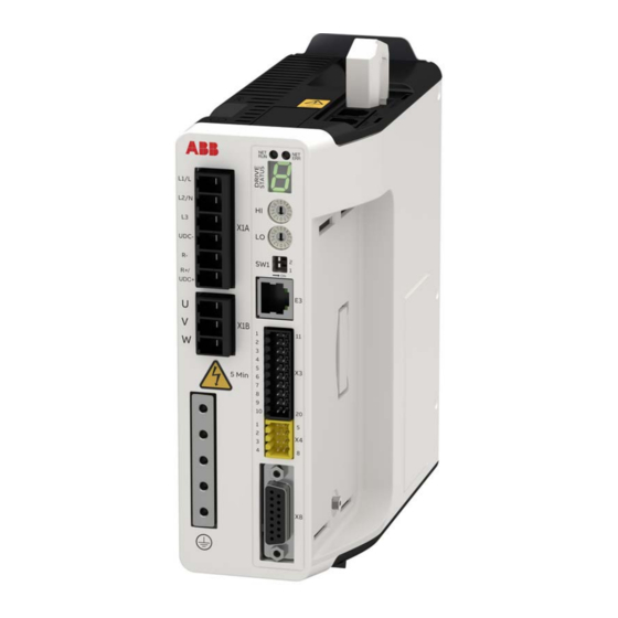
Page 28: Layout - Front
28 Operation principle and hardware description Layout - front Fieldbus status LEDs (page 111) 7-segment display (page 114) AC supply connection (page 51) Fieldbus mode selectors (page 75) DC supply connection (page 54) Start-up function selectors (page 72) Brake resistor connection (page 171) PC host Ethernet connection (page 75) Option card (page 182) -
Page 29: Layout - Top
Operation principle and hardware description 29 Layout - top Memory unit (page 32) Ethernet fieldbus ports (page 74) PE connection (page 53) Layout - bottom Optional 24 V control circuit supply input (page 56) Incremental encoder feedback input (page 83) X8 voltage output selector (page 78) -
Page 30: Main Circuit
Electrical installation: AC input / DC input, motor and brake. AC supply 1-phase or 3-phase supply Mains choke (optional) R+/UDC+ UDC- L2 L3 Mains filter MicroFlex e190 – Inverter R+/UDC+ Motor output RGJxxx braking resistor (optional) 1. AC supply. 1-phase 200...240 V or 3-phase 200...240 V phase-to-phase (±10%). -
Page 31: Type Designation Label
The type code contains information on the specifications and configuration of the drive. The type code is explained in the following table. Not all selections are necessarily available for all types; refer to MicroFlex e190 Ordering Information, available on request. -
Page 32: Memory Unit - Mu
Retuning the drive using Mint WorkBench allows the correct tuning parameters to be saved in the memory unit. The memory unit can be used only with MicroFlex e190 drives. It is not compatible with any other product that uses a similar unit, e.g. ZMU-02. The MicroFlex e190 memory unit can be identified by the part MFE190-MU-OCU+N8020 on the label and provide motion programming capability.... -
Page 33: Mechanical Installation
Mechanical installation 33 Mechanical installation What this chapter contains The chapter describes the mechanical installation of the drive. -
Page 34: Contents Of The Package
34 Mechanical installation Contents of the package The box contains: • MicroFlex e190 drive • Connector pack containing terminal blocks for the drive. • Memory unit • Quick Installation Guide. Quick Installation Guide MicroFlex e190 Connector pack... -
Page 35: Main Dimensions
Mechanical installation 35 Main dimensions MicroFlex e190 drives can be installed side by side. The main dimensions of the drive and free space requirements are shown below. Ø 5 (0.20) Ø 12 Unit:mm(inches) (0.47) 200* (7.87) 73.45 (2.89) (6.10) (2.83) * Approximate dimensions. -
Page 36: Cabinet Construction
36 Mechanical installation Cabinet construction The cabinet frame must be sturdy enough to carry the weight of the drive components, control circuitry and other equipment installed in it. The cabinet must protect the drive against contact and meet the requirements for dust and humidity (see the chapter Technical data). - Page 37 Mechanical installation 37 Consider this when installing heat-generating components (such as other drives and braking resistors) nearby. The drawing below shows two typical cabinet cooling solutions. The air inlet is at the bottom of the cabinet, while the outlet is at the top. Air outlet Air outlet Air inlet...
-
Page 38: Disposition Of The Devices
38 Mechanical installation Disposition of the devices For easy installation and maintenance, a spacious layout is recommended. Sufficient cooling air flow, obligatory clearances, cables and cable support structures all require space. For layout examples, see section Cooling and degrees of protection. -
Page 39: Grounding Of Mounting Structures
Requirements for the installation site The drive must be installed in an upright position with the mounting plate against a wall. MicroFlex e190 drives can be installed tightly side by side. Make sure that the installation site complies with these requirements: •... -
Page 40: Direct Wall Mounting
40 Mechanical installation Direct wall mounting 1. Mark the locations for the two holes. The mounting points are shown in Main dimensions on page 35. 2. Fix the screws or bolts to the marked locations. 3. Position the drive onto the screws on the wall. Note: Only lift the drive by its chassis. -
Page 41: Planning The Electrical Installation
Note: The installation must always be designed and made according to applicable local laws and regulations. ABB does not assume any liability whatsoever for any installation which breaches the local laws and/or other regulations. -
Page 42: Supply Disconnecting Device
US fuses must be of the CC “fast acting” type. Circuit breakers cannot be used with the MicroFlex e190 for UL compliant applications. Fuses must be used. -
Page 43: Motor Thermal Protection
Residual current device (RCD) compatibility MicroFlex e190 drives are suitable to be used with residual current devices of Type B. Other measures for protection in case of direct or indirect contact, such as separation from the environment by double or reinforced insulation or isolation from the supply... -
Page 44: Safe Torque Off
(see diagram below). By using this function, short-time operations (like cleaning) and/or maintenance work on non- electrical parts of the machinery can be performed without switching off the power supply to the drive. MicroFlex e190 X4:4 Activation +24 V... -
Page 45: Selecting The Power Cables
Planning the electrical installation 45 Selecting the power cables General rules Dimension the supply (input power) and motor cables according to local regulations. • The cable must be able to carry the drive load current. See the chapter Technical data for the rated currents. -
Page 46: Motor Cable Shield
46 Planning the electrical installation Motor cable shield To function as a protective conductor, the shield must have the same cross-sectional area as a phase conductor when they are made of the same metal. To effectively suppress radiated and conducted radio-frequency emissions, the shield conductivity must be at least 1/10 of the phase conductor conductivity. -
Page 47: Routing The Cables
Planning the electrical installation 47 Routing the cables Route the motor cable away from other cable routes. Motor cables of several drives can be run in parallel installed next to each other. It is recommended that the motor cable, input power cable and control cables be installed on separate trays. Avoid long parallel runs of motor cables with other cables in order to decrease electromagnetic interference caused by the rapid changes in the drive output voltage. -
Page 48: Typical Installation Example
48 Planning the electrical installation Typical installation example Footprint filter OFI-01 DO NOT TOUCH! saves panel space. Brake resistors can become The filter can be inverted extremely hot! Locate away from CAUTION if the AC input is above vulnerable components and wiring. the drive. -
Page 49: Electrical Installation: Ac Input / Dc Input, Motor And Brake
Electrical installation: AC input / DC input, motor and brake 49 Electrical installation: AC input / DC input, motor and brake What this chapter contains The chapter describes how to connect input power cables, motor and brake resistor. WARNING! The work described in this chapter may only be carried out by a qualified electrician. -
Page 50: Checking The Insulation Of The Assembly
50 Electrical installation: AC input / DC input, motor and brake Checking the insulation of the assembly Drive Do not make any voltage tolerance or insulation resistance tests (e.g. hi-pot or megger) on any part of the drive as testing can damage the drive. Every drive has been tested for insulation between the main circuit and the chassis at the factory. -
Page 51: Power Cable Connection
(page 42). Mains filter (optional). See the chapter Mains filters (page 165). The UDC+/UDC- connectors can be used for common DC configurations. See page 54. MicroFlex e190 L1/L L2/N UDC- UDC+ Optional braking resistor (see the chapter Resistor... -
Page 52: Procedure
52 Electrical installation: AC input / DC input, motor and brake Procedure Cabling drawings with tightening torques are presented on page 53. 1. Strip the power cables so that the shields are bare at the cable clamps. 2. Twist the ends of the cable shield wires into pigtails. 3. - Page 53 Electrical installation: AC input / DC input, motor and brake 53 AC power cable connection Supply cable Cable clamp on bare shield Cover bare shield with insulating tape 0.5...0.6 N·m (4.4...5.3 lbf·in) M4, 10 mm max. 1.0...1.3 N·m (8.9...11.5 lbf·in) 0.5...0.6 N·m (4.4...5.3 lbf·in) Motor earth wire M4, 10 mm max.
-
Page 54: Dc Power Cable Connection Diagram (Optional)
DC supply MicroFlex e190 can use a DC supply as the primary power source (see page 154). Each drive is powered from the DC supply and has its own brake resistor. There is no AC supply. - Page 55 Electrical installation: AC input / DC input, motor and brake 55 Each drive has an independent DC capacitor pre-charging circuit. UDC+ UDC- L2 L3 – Pre-charging circuit The ratings of the DC connection are given on page 154.
-
Page 56: Control Circuit Supply (Optional)
AC (or DC) power supply is removed from the power stage, but the controlling electronics must remain powered to retain position, I/O information and communications. A separate fused 24 V supply should be provided for the MicroFlex e190. Customer supplied 24 V DC... -
Page 57: Motor Brake Connection
You can wire a motor's brake, via relays, to a digital output on connector X3; see Connecting the control cables on page 60. This provides a way for the MicroFlex e190 to control the motor's brake. A typical circuit is shown in the following diagram: User... -
Page 58: Thermal Switch Connection
Thermal switch connection You can use the motor's thermal switch contacts (normally closed), to control a relay connected to a digital input on connector X3. This allows the MicroFlex e190 to respond to motor over-temperature conditions. Using the Mint WorkBench Digital I/O tool, the input can be configured to be the motor temperature input. -
Page 59: Electrical Installation: Input / Output
Electrical installation: input / output 59 Electrical installation: input / output What this chapter contains The chapter describes how to connect low voltage control signals. The following conventions will be used to refer to the inputs and outputs: Input / Output Analog Input... -
Page 60: Connecting The Control Cables
60 Electrical installation: input / output Connecting the control cables E1/E2 Ethernet fieldbus AC input 200...240 V AC ±10% DC bus- UDC- Brake- DC bus+ / Brake+ R+/UDC+ Motor output Ethernet host (PC) Status-/DO0- Status-/DO0+ DO2- DO2+ DO1- DO1+ DI2- DI2+ DI3- DI3+... -
Page 61: Analog I/O
When the MicroFlex e190 is connected to Mint WorkBench, the analog input value (expressed as a percentage) can be viewed using the Spy window’s Monitor tab. Alternatively, the command Print ADC(0) can be used in the command window to return the value of the analog input. - Page 62 PLC/controller MicroFlex e190 +15V AI0+ Mint ADC.0 AI0- -15V Shield Connect overall shield at one end only Analog input - typical connections from an ABB AO561: AO561 MicroFlex e190 +15V O0U+ AI0+ Mint ADC.0 AI0- O01- -15V Connect overall shield at one...
-
Page 63: X3: Analog Output Ao0
DAC and other related DAC... keywords. Analog output - typical connections to a PLC/controller: PLC/controller MicroFlex e190 Shield Connect overall shield at one end only Analog output - typical connections to an ABB AI523: AI523 MicroFlex e190 Shield Connect overall shield at one end only... -
Page 64: Digital I/O
MicroFlex e190 to supply power to the motor. If an additional hardware drive enable input is used to control the MicroFlex e190, it must not be wired with the STO input circuit. The state of the STO inputs can be viewed using the Mint WorkBench Spy window's Axis tab or via the Mint SAFETORQUEOFF keyword. -
Page 65: X3: Digital Inputs - General Purpose Di1 & Di2
X3: Digital inputs - general purpose DI1 & DI2 These general purpose fast digital inputs are buffered by an opto-isolator, allowing the input signal to be connected with either polarity. When the MicroFlex e190 is connected to Mint WorkBench, the digital inputs can be configured using the Digital I/O tool. -
Page 66: Special Functions On Inputs Di1 & Di2
66 Electrical installation: input / output Special functions on inputs DI1 & DI2 DI1 and DI2 can be configured to perform special functions. The ENCODERMODE keyword controls the configuration. When operating as an encoder input or step and direction inputs, DI1 and DI2 can be used for a dual-loop feedback system or connected to a master encoder for position following applications (see the FOLLOW, FLY and CAM keywords in the Mint help file). - Page 67 DIN1+ with the signal for DIN1- and twist the signal for DIN2+ with the signal for DIN2-). Step and direction inputs - typical connections from a PLC/controller using open emitter outputs: PLC/Controller MicroFlex e190 User supply 24 V Step...
- Page 68 68 Electrical installation: input / output Step and direction inputs - typical connections from a PLC/controller using open collector outputs: PLC/Controller MicroFlex e190 User supply 24 V Step Twisted pairs DI1+ TLP118 DI1- Step Step Output Shield User supply 24 V...
-
Page 69: X3: Digital Inputs - General Purpose Di0 & Di3
X3: Digital inputs - general purpose DI0 & DI3 These general purpose digital inputs are buffered by an opto-isolator, allowing the input signals to be connected with either polarity. When the MicroFlex e190 is connected to Mint WorkBench, the digital inputs can be configured using the Digital I/O tool. - Page 70 70 Electrical installation: input / output Digital input - typical current sourcing connections to a digital input: User MicroFlex e190 supply 24 V DI0+ DI0- User supply...
-
Page 71: X3: Digital Outputs - General Purpose Do0 - Do3
This is to protect the output from the back-EMF generated by the load when it is de-energized. When the MicroFlex e190 is connected to Mint WorkBench, the active level of the output can be configured using the Digital I/O tool. Alternatively, the Mint keyword OUTPUTACTIVELEVEL can be used in the command window. -
Page 72: Other I/O
72 Electrical installation: input / output Digital output - typical connections to an ABB DI561 PLC input module: User supply DI561 MicroFlex e190 24 V DO1+ DO1- C0..7 User supply Other I/O X2: External power supply for the control unit (optional) An external +24 V, 1 A power supply for the control board can be connected to terminal block X2. -
Page 73: Control Cable Grounding
Electrical installation: input / output 73 Control cable grounding The shields of all control cables must be grounded at the earth bar. Use M4 screws to fasten cable clamps. The shields should be continuous as close to the terminals as possible. Only remove the outer jacket of the cable at the cable clamp so that the clamp presses on the bare shield. -
Page 74: Ethernet Ports
(NC) (NC) (NC) The E1 and E2 Ethernet ports on the top panel of the MicroFlex e190 are used for real-time Ethernet fieldbus connections such as EtherCAT® and Ethernet POWERLINK®. For full details about the fieldbus connections, see the Mint WorkBench help file. -
Page 75: E1 / E2: Ethernet Port Configuration
Ethernet POWERLINK CN mode: selected value is node ID F0-FF Reserved E3: Ethernet host The Ethernet host port is used to connect a PC for configuring the MicroFlex e190. See section Start-up on page for details about configuring the PC’s Ethernet adapter for communication with the MicroFlex e190. -
Page 76: Motor Feedback (X8)
76 Electrical installation: input / output Motor feedback (X8) MicroFlex e190 supports incremental encoder, EnDat 2.1, SinCos, BiSS-B (Bi- directional Synchronous Serial Interface), SSI (Synchronous Serial Interface), EnDat 2.2, Smart Abs absolute encoder or Hiperface feedback, for use with linear and rotary motors. -
Page 77: Incremental Encoder With Halls
Electrical installation: input / output 77 Twisted pairs must be used for each complementary signal pair e.g. CHA+ and CHA- or Data+ and Data-. The overall cable shield (screen) must be connected to the metallic shell of the D- type connector. In Mint WorkBench, the primary motor feedback encoder on connector X8 is encoder 0. -
Page 78: Serial Interfaces & Sincos
78 Electrical installation: input / output Serial interfaces & SinCos The MicroFlex e190 supports the following feedback types, for use with linear and rotary motors: • EnDat 2.1 • SinCos encoders (1 V pk-pk, 2.5 V reference) • BiSS-B (Bi-directional Synchronous Serial Interface), SSI (Synchronous Serial Interface) or EnDat 2.2... - Page 79 Electrical installation: input / output 79 EnDat interface Incremental and absolute (multi and single turn) devices are supported. It is possible to read and write information to the encoder. The Sin and Cos channels are not required when using a version 2.2 EnDat encoder. EnDat 2.1 interface cable connections: Motor Twisted pairs...
- Page 80 80 Electrical installation: input / output SSI encoders SSI interface cable connections: Motor Twisted pairs Absolute Data+ Encoder Data- Clock+ Clock- +5.5 V out Connect DGND internal shields to pin 13. Chassis Connect overall shield to connector backshells Smart Abs encoders Smart Abs interface cable connections: Motor Twisted pairs...
-
Page 81: Extra Incremental Encoder
Electrical installation: input / output 81 Extra incremental encoder Some applications require the connection of multiple encoders typically when: • A single axis has multiple encoders on the same motion system to eliminate mechanical errors (a dual encoder application). •... - Page 82 82 Electrical installation: input / output X8B (extra Inc. encoder without Halls) Corresponding pin on X8 CHA+ CHB+ CHZ+ (NC) (NC) DGND CHA- CHB- CHZ- +5.5 V out The inputs may be used as differential inputs (recommended for improved noise immunity) or single ended inputs.
-
Page 83: Incremental Encoder Input/Output (X7)
Electrical installation: input / output 83 Incremental encoder input/output (X7) The incremental encoder input/output connection provides A/B channels and a Z index channel. Twisted pairs must be used for each complementary signal pair e.g. CHA+ and CHA-. The Mint keyword ENCODEROUTCHANNEL is used to set the mode of operation for X7. - Page 84 • The B channel pins (2 & 7) are used as the direction input. The state of the direction input controls the direction of motion. • The Z channel input is not used. Step / direction inputs - typical connections from a PLC/controller: PLC/controller MicroFlex e190 Step+ Step output Step-...
-
Page 85: Opt-Mf-201 Resolver Adapter
ENCODEROUTCHANNEL(0)=n, where n is 0, 1, or 2, as described above. On the menu, choose Tools, Store Drive Parameters. OPT-MF-201 Resolver adapter The optional resolver adapter OPT-MF-201 allows a motor with resolver feedback to be connected to the MicroFlex e190. See page for details. -
Page 86: Supported Feedback Type
The right feedback type for your application is automatically set when the motor is selected in Mint WorkBench.The Mint keyword ENCODERTYPE can also be used to define the feedback type of encoder input. Moreover, MicroFlex e190 supports two different types of incremental encoder signal inputs, see more details below. - Page 87 Electrical installation: input / output 87 The MicroFlex e190 has 3 encoder input channels: • Encoder 0: Primary encoder input on connector X8 (see page 76). • Encoder 1: Extra optional incremental encoder input on connector X3 (see page 66).
-
Page 88: Encoder 0 Input
Linear incremental encoder with Halls ENCODERTYPE(0)=3 Rotary Hall sensors only without encoder ENCODERTYPE(0)=4 Hall sensor Linear Hall sensors only without encoder ENCODERTYPE(0)=5 Baumer SSI encoder of ABB motor ENCODERTYPE(0)=6 Linear SSI encoder ENCODERTYPE(0)=19 Generic SSI encoder ENCODERTYPE(0)=24 Rotary EnDat v2.1 ENCODERTYPE(0)=7 Rotary EnDat v2.2... -
Page 89: Encoder 1 Input
Electrical installation: input / output 89 Encoder 1 input Encoder 1 is an extra incremental encoder input channel and can be used to set up dual-encoder control system or be connected to a master encoder. It comes from fast digital inputs 1 and 2 on connector X3. - Page 90 90 Electrical installation: input / output...
-
Page 91: Installation Checklist
Motor connection.) ELECTRICAL INSTALLATION (See Planning the electrical installation, Electrical installation: AC input / DC input, motor and brake.) The capacitors are reformed if stored over one year (ask local ABB representative for more information). The drive is grounded properly. - Page 92 92 Installation checklist Check The supply (input power) voltage matches the drive nominal input voltage. The supply (input power) is connected to L1/L2/L3 (UDC+/UDC- in case of a DC supply) and the terminals are tightened to specified torque. Appropriate supply (input power) fuses and disconnector are installed. The motor is connected to U/V/W, and the terminals are tightened to specified torque.
-
Page 93: Start-Up
Introduction Before powering the MicroFlex e190 you must connect it to the PC using an Ethernet cable and install the Mint WorkBench software on the PC. This includes a number of applications and utilities to allow you to configure, tune and program the MicroFlex e190. -
Page 94: Install Mint Workbench
It is necessary to alter the PC's Ethernet adapter configuration to operate correctly with the MicroFlex e190. By default, the MicroFlex e190 has a static IP address of 192.168.0.1. This can be changed using the Configuration tool in Mint WorkBench. -
Page 95: Enable The Ethernet Adapter For Mint Workbench
STO input (page 187) is not powered. Start-up can take more than 1 minute after downloading new firmware. 4. To allow the Commissioning Wizard to function, the Safe Torque Off inputs (page 187) must be powered to allow the MicroFlex e190 to be enabled. -
Page 96: Start Mint Workbench
4. Select the MicroFlex e190 in the list, and check Launch Commissioning Wizard. 5. Click Select. Note: If the MicroFlex e190 is not listed, check the Ethernet cable is connected to the E3 port on the front panel of the drive, not E1 or E2 on the top panel. Check that the... -
Page 97: Commissioning Wizard
By monitoring the drive's output and the feedback from the motor's encoder, the MicroFlex e190 can make small adjustments to the way it controls the motor. This information is stored in the MicroFlex e190 and can be uploaded to a file if necessary. - Page 98 WorkBench. Although the MicroFlex e190 might eventually be controlled over EtherCAT (or Ethernet POWERLINK), the ‘RT Ethernet' reference source should be selected only after the MicroFlex e190 has been commissioned and is ready to add to the EtherCAT (or Ethernet POWERLINK) network. This is selected by choosing the Operating Mode tool in the Toolbox.
-
Page 99: Further Tuning - No Load Attached
This screen confirms that operation setup is complete. Autotune Wizard The Autotune Wizard tunes the MicroFlex e190 for optimal performance with the attached motor. This removes the need for manual fine-tuning of the system, although in some critical applications this might be required. - Page 100 100 Start-up Some tabs might not be available depending on the configuration mode you selected in the Commissioning Wizard. 3. In the Test Parameters area at the bottom of the tab, click in the Move Type drop down box and select Forward. ...
-
Page 101: Further Tuning - With Load Attached
Start-up 101 For further information about tuning with the load attached, see Further tuning - with load attached on page 101. Further tuning - with load attached To allow Mint WorkBench to adjust the basic tuning to compensate for the intended load, it is necessary to attach the load to the motor and then perform the autotune procedure again. -
Page 102: Optimizing The Velocity Response
102 Start-up Optimizing the velocity response It can be desirable to optimize the default autotuned response to better suit your application. The following sections describe the two main tuning factors and how to correct them. Correcting overshoot The following graph shows a response where the measured velocity overshoots the demand by a significant amount. -
Page 103: Correcting Zero-Speed Noise In The Velocity Response
Start-up 103 Correcting zero-speed noise in the velocity response The following graph shows a response where there is very little overshoot but a significant amount of zero-speed noise. This can cause undesirable humming or ringing in the motor. 1. Go to the Fine-tuning window's Velocity tab. ... -
Page 104: Ideal Velocity Response
104 Start-up Ideal velocity response Repeat the tests described in Correcting overshoot and Correcting zero-speed noise in the velocity response until the optimal response is achieved. The following graph shows an ideal velocity response. There is only a small amount of overshoot and very little zero-speed noise. -
Page 105: Performing Test Moves - Relative Positional Move
Start-up 105 the axis tab is selected. The Spy window's Velocity display should show 10 (approximately). If there seems to be very little motor movement, it is probably due to the scale factor. In the Commissioning Wizard, on the Select Scale Factor page, if you did not adjust the scale factor then the current unit of movement is feedback counts per second. -
Page 106: Further Configuration
Mint WorkBench provides a number of other tools for testing and configuring the MicroFlex e190. Every tool is explained fully in the help file. Press F1 to display the help file, then navigate to the Mint WorkBench book. Inside this is the Toolbox book. -
Page 107: Parameters Tool
3. The adjacent table lists the chosen item. Click in the Active Table cell and enter a value. This immediately sets the parameter, which remains in the MicroFlex e190 until another value is defined or power is removed. The icon to the left of the item becomes yellow to indicate that the value has been changed. -
Page 108: Other Tools And Windows
This tool provides a work area including the Command window and Output window. The Command window can be used to send immediate Mint commands to the MicroFlex e190. If you tried the test moves in Performing test moves - continuous jog... -
Page 109: Fault Tracing
Problem diagnosis If you have followed all the instructions in this manual in sequence, you should have few problems installing the MicroFlex e190. If you do have a problem, read this section first. • In Mint WorkBench, use the Error Log tool to view recent errors and then check the help file. -
Page 110: Power-Cycling The Microflex E190
Power-cycling the MicroFlex e190 The term ‘power-cycle the MicroFlex e190’ is used in the Troubleshooting sections. If the mains AC supply (or DC supply) is removed, wait for 2 minutes before reapplying the supply. -
Page 111: Microflex E190 Indicators
Fault tracing 111 MicroFlex e190 indicators EtherCAT® mode The Ethernet LEDs display the overall condition of the Ethernet interface once the startup sequence has completed. The LED codes conform to the EtherCAT Technology Group (ETG) standard at the time of production. -
Page 112: Ethernet Powerlink Mode
112 Fault tracing NET RUN (Green) Off: INITIALISATION state (or not powered). Blinking: PRE-OPERATIONAL state. 1 flash: SAFE-OPERATIONAL state. 3 flashes: Device identification. This state can be set from the master to locate the device. Continuously illuminated, not flashing: Node in OPERATIONAL state. EtherCAT is operating normally. - Page 113 Fault tracing 113 Red (error) Off: Ethernet POWERLINK is working correctly. Continuously illuminated: An error has occurred. LED flash periods The following diagram shows the definitions of the terms ‘blinking’, ‘flashing’ and ‘flickering’ used in the previous sections, as defined by the EtherCAT Technology Group.
-
Page 114: Drive Status Display
The decimal point to the right of the number also illuminates to indicate STO errors. If symbol appears followed by an error code, please contact ABB technical support. For a complete list of error codes, open Mint WorkBench, press F1, and locate the Error Handling book. - Page 115 Fault tracing 115 Symbol Description Drive enabled, but idle. Cam move. A cam profile is in progress. See the Mint keyword CAM. Dwell. A dwell (wait) ‘move’ is in progress. See the Mint keyword MOVEDWELL. Flying shear. A flying shear is in progress. See the Mint keyword FLY. Follow move.
-
Page 116: Power
54) must be present at X1 to allow communication. Drive status display shows ‘I’: • The MicroFlex e190 is in firmware recovery mode. This means that it does not boot fully, and allows Mint WorkBench to download firmware from the Choose Firmware dialog. -
Page 117: Tuning
Configure the PC Ethernet adapter on page 94. How do I configure my EtherCAT manager to operate with the MicroFlex e190? • An EtherCAT ESI file (.xml) that describes the drive to the EtherCAT manager can be uploaded from the controller using the Mint WorkBench EtherCAT tool.... - Page 118 • Set the CONTROLREFSOURCESTARTUP parameter to '1' using the Mint WorkBench Parameter viewer or Command window, save the parameters and restart the drive. This gives control to the manager each time the MicroFlex e190 starts. • Set the Control Ref. Source to ‘RT Ethernet (CiA402)’ in the Mint WorkBench Operating Mode Wizard or Commissioning Wizard.
-
Page 119: Warning Messages Generated By The Drive
Fault tracing 119 Warning messages generated by the drive Axis warnings Code Warning Cause What to do 20003 All axis warnings cleared This information message can No Action required (_ecAXIS_WARNINGS_CLEA appear in the error log to indicate RED) that all axis warnings have been cleared. -
Page 120: Controller Warnings
120 Fault tracing Controller warnings Code Warning Cause What to do 40006 Attempt to configure too The device configuration file Re-run the System Configuration Wizard . many axes has attempted to assign (_ecTOO_MANY_AXES) more axes than are available on the controller. 40007 CamBox segments have The cam box has skipped a... - Page 121 MAC CTED) address is not set. 40024 Could not open license file or Could not open license file If this error is received, please contact ABB Error reading license file or Error reading license file technical support. (_ecMISSING_LICENCE_FI 40025...
-
Page 122: Error Messages Generated By The Drive
122 Fault tracing Error messages generated by the drive Autotuning errors Code Error Cause What to do 4000 No autotuning error There is no autotuning error. No Action (_ecAUTOTUNE_SUCCESS) 4001 Drive rating data invalid One of the following conditions Check memory module is connected has not been met correctly, check power supply level is... - Page 123 Fault tracing 123 Code Error Cause What to do 4010 Resistance too low, possible short This error can occur during the Check that there are no short circuits circuit Measure motor resistance and between the U, V and W terminals (_ecPOSSIBLE_SHORT_CIRCUIT inductance test and indicates of the motor and that the motor power...
- Page 124 Information page of the Drive Setup incremental encoder + Halls Wizard to check these values. If the feedback system. resolver is not a standard ABB product, check that the specification is compatible in the drives hardware manual •A common cause of this error is an incorrectly wired or set up encoder/resolver.
- Page 125 Fault tracing 125 Code Error Cause What to do 4016 Mathematic error in gain This error can occasionally occur The error can usually be cleared by calculations during the Calculate current loop changing the design bandwidth for (_ecGAIN_CALCS_FAILED) gains or Calculate the speed the appropriate operation (click and position gains tests, Options...
- Page 126 126 Fault tracing Code Error Cause What to do 4020 Can't fit load model speed data During the Measure the motor Click Options... in the Autotune tool (_ecCANNOT_FIT_LOAD_MODEL inertia test, a torque waveform is and then select the Limits tab. applied by the motor and the Increase the value in the Max Travel motor speed logged.
- Page 127 Fault tracing 127 Code Error Cause What to do 4023 Not enough test data to analyse This error can occur during any See errors 4018 , 4019 and 4020 for (_ecINSUFFICIENT_TEST_DATA) of the autotuning tests, namely the reasons why these tests fail. the Measure motor resistance and inductance test, the Measure the voltage constant...
- Page 128 128 Fault tracing Code Error Cause What to do 4028 Can't set stator resistance Can't set stator resistance. Error codes 4028 to 4054 will occur if (_ecCANNOT_SET_STATOR_RE the associated drive parameter, SISTANCE) calculated by one of the autotuning tests, or set by the user is outside the 4029 Can't set stator leakage inductance Can't set stator leakage...
- Page 129 Fault tracing 129 Code Error Cause What to do 4048 Voltage constant test failed Voltage constant measurement Error codes 4028 to 4054 will occur if (_ecVOLTAGE_CONSTANT_TES failed the associated drive parameter, T_FAILED) calculated by one of the autotuning tests, or set by the user is outside the 4049 Can't set offset angle Can't set motor feedback offset...
- Page 130 130 Fault tracing Code Error Cause What to do 4063 Encoder fault General Encoder fault Check encoder configuration, wiring (_ecPOSSIBLE_ENCODER_FAUL and encoder operation when rotating by hand. 4065 Test move will take too long Test move takes too long time in. Check that test moves are set so that they will not take an excessive amount of time, Also check scaling is set correctly by checking...
-
Page 131: Parameter Errors
Fault tracing 131 Parameter errors Code Error Cause What to do 6001 Parameter value out of range The value supplied for the The value you have entered or that is (_ecPARAM_VALUE_OUT_OF_R parameter is out of range. stored in the parameter file (.ptx) you have ANGE) loaded does not fit within the limits specified by the drive firmware version... -
Page 132: Communication Errors
132 Fault tracing Communication errors Code Error Cause What to do 8000 EtherCAT AL status code This error is listed together with a This error status indicates that the (_ecETHERCAT_AL_STAT Profile Code in the Mint WorkBench EtherCAT master has been sent an USCODE) Error Log. -
Page 133: Axis Errors
Fault tracing 133 Axis errors Code Error Cause What to do 10000 Motion aborted This error is caused by using the The ABORT keyword has been issued by (_ecABORT) ABORT keyword or breaking a the mint program. This may be normal in Mint program. - Page 134 134 Fault tracing Code Error Cause What to do 10009 Invalid trajectory Trajectory generation error. The Check Mint CAM parameter file for (_ecPROFILE_ERROR) controller was unable to perform anamolus Data points. Excel is a helpful the requested profile. This can tool to help with this.
- Page 135 Fault tracing 135 Code Error Cause What to do 10015 Over speed trip The drive has detected the Note: If this error occurs when using a (_ecOVER_SPEED) apparent motor velocity has Smart Inc encoder, see Smart Inc exceeded the trip threshold set by encoders (setting a high application max DRIVESPEEDMAX and the speed and 200% velocity threshold may...
- Page 136 136 Fault tracing Code Error Cause What to do 10020 Phase search failure Phase search must be completed Phase search must be completed to (_ecPHASE_SEARCH_FA to control a motor with type control a motor with type "encoder only"- ILED) "encoder only" if it does not finish successfully check encoder settings in drive and check the correct number of motor poles has been...
- Page 137 Fault tracing 137 Code Error Cause What to do 10028 Encoder not ready to The drive is configured to use a The encoder may take several seconds operate Serial Encoder and it is not able to to become ready and this error will be (_ecENCODER_NOT_RE provide position information.
- Page 138 138 Fault tracing Code Error Cause What to do 10034 STO hardware fault Either one or both of the internal Check drive STO inputs, if used check (_ecSTO_HARDWARE_F fault circuit outputs has been the wiring of the safety circuit or for open AULT) asserted, indicating an internal guards or Emergency stops etc.
-
Page 139: Controller Errors
Fault tracing 139 Controller errors Code Error Cause What to do 30001 Controller The drive has detected it is Check the drive ambient conditions allow over-temperature dangerously hot. for sufficient cooling. (_ecOVER_TEMPERATU Note: TEMPERATURE will return the current temperature, in degrees Celsius, from the drive's internal temperature sensor. - Page 140 '0' then this error will be generated. Old drives will still work in every other mode but if EPL is needed the Hardware will need to be exchanged AN00267 ABB Motion Drives Error trouble shooting manual for more details on error handing.
-
Page 141: Maintenance
Ignoring the safety instructions can cause injury or death. Maintenance intervals If installed in an appropriate environment, the drive requires very little maintenance. This table lists the routine maintenance intervals recommended by ABB. Maintenance Interval Instruction... -
Page 142: Heat Sink
142 Maintenance Heat sink The heat sink fins pick up dust from the cooling air. The drive might report overtemperature warnings and faults if the heat sink is not clean. In a normal environment, the heat sink should be checked annually, in a dusty environment more often. -
Page 143: Cooling Fan
If the drive is operated in a critical part of a process, fan replacement is recommended once these symptoms start appearing. Replacement fans are available from ABB. Do not use other than ABB-specified spare parts. -
Page 144: Replacing The Fan
144 Maintenance Replacing the fan Insert the new fan (1) ensuring the airflow direction is bottom-to-top. Route the wire through the retaining clip and connect the cable to the circuit board (2). Insert the front edge of the base into the front panel (3). Apply outward pressure at the centre of the base and simultaneously push the fan into the drive (4). -
Page 145: Reforming The Capacitors
The capacitors must be reformed if the drive has been stored for a year or more. See page for information on finding out the manufacturing date. For information on reforming the capacitors, contact your local ABB representative. Other maintenance actions ... - Page 146 146 Maintenance...
-
Page 147: Technical Data
Technical data 147 Technical data What this chapter contains The chapter contains the technical specifications of the drive, for example, the ratings, sizes and technical requirements as well as provisions for fulfilling the requirements for CE and other marks. -
Page 148: Ratings
148 Technical data Ratings The nominal current ratings for the MicroFlex e190 with 200...240 V AC supply are given below. For example, if a 6 A model is required to provide brief 300% overloads, assume its rated current is only 5.3 A. -
Page 149: Derating
Technical data 149 Derating The continuous output currents stated above must be derated if any of the following conditions apply. The final derating factor is a multiplication of all applicable derating factors. Ambient temperature derating: 1.6 A models A temperature derating is required when operating the 1.6 A models in ambient temperatures between 45 °C (+113 °F) and the maximum of 50 °C (122 °F): ... -
Page 150: Cooling
150 Technical data Cooling Method Internal fan, flow from bottom to top, air-cooled heat sink. Free space around the Cooling and degrees of protection on page unit Cooling characteristics, noise levels Drive type Power loss Air flow Noise level MFE190-04xx... -01A6-2 (No fan) (No fan) -
Page 151: Supply Cable Fuses
Technical data 151 Supply cable fuses Fuses for short circuit protection of the supply cable are listed below. The fuses also protect the adjoining equipment of the drive in case of a short circuit. Check that the operating time of the fuse is below 0.5 seconds. The operating time depends on the supply network impedance and the cross-sectional area and length of the supply cable. -
Page 152: Ac Input (Supply) Connection
152 Technical data AC input (supply) connection 1Φ 3Φ Voltage (U 200...240 V AC ±10% 200...240 V AC ±10% 50...60 Hz ± 5% Frequency Grounded (TN, TT). Network type Corner grounded TN, and IT (ungrounded) systems not allowed. Imbalance Max. ± 3% of nominal phase to phase input voltage Fundamental power 0.98 (at nominal load) - Page 153 Technical data 153 Effect of AC power supply voltage on DC-bus ripple voltage 9 A model, single-phase AC supply 1.6 A, 3 A, 6 A models, single-phase AC supply All models, three-phase AC supply AC supply voltage (RMS) Effect of output current on DC-bus ripple voltage 9 A model, single-phase AC supply 1.6 A, 3 A, 6 A models, single-phase AC supply All models, three-phase AC supply...
-
Page 154: Dc Input (Supply) Connection
154 Technical data DC input (supply) connection Voltage 270...340 V DC ±10% Drive type Ratings MFE190-04xx... (µF) -01A6-2 1.96 -03A0-2 3.67 -06A0-2 7.35 1120 -09A0-2 11.02 1120 is the average DC input current requirement. Terminals Detachable screw terminal block for 0.20...6 mm wire. -
Page 155: Control Unit
Technical data 155 Control unit X2: Control circuit supply 24 V (±10%) DC, 1 A input Optional external power supply through connector X2 (pitch 5.08 mm, wire size 2.5 mm X3: Analog input AI0 Connector pitch 3.5 mm, wire size 1.0 mm Voltage input: –10…10 V, R : 60 kohm... -
Page 156: Feedback
156 Technical data Feedback X7 Incremental encoder without Halls Encoder interface RS422 A/B differential, Z index Max. input frequency A / B 2 MHz (8 MHz quadrature counts) Output power supply to encoder 5.5 V DC (±7%) 500 mA max.* Maximum recommended cable 30 m length... -
Page 157: Dimensions And Weights
Technical data 157 Dimensions and weights For basic weights and dimensions, see Main dimensions on page 35. Ambient conditions Environmental limits for the drive are given below. The drive is to be used in a heated, indoor, controlled environment. Operation Storage Transportation installed for stationary... -
Page 158: Degrees Of Protection
Degrees of protection MicroFlex e190 complies with EN 60529, IP20. For UL purposes the MicroFlex e190 is defined as an open-type, three phase single axis servo amplifier. The drive must be installed in a cabinet to fulfill the requirements for shielding from contact. -
Page 159: Rohs Compliance
RoHS compliance MicroFlex e190 is in conformity with Directive 2011/65/EU of the European parliament and of the council of 8th June 2011 on the restriction of the use of certain hazardous substances in electrical and electronic equipment. The RoHS declaration 3AXD10000540158 is available on new.abb.com/motion. -
Page 160: Applicable Standards
Adjustable speed electrical power drive systems. Electromagnetic A1:2012 compatibility. Conducted emissions: When installed as directed in this manual, MicroFlex e190 conforms to Category C2 conducted limits. Radiated emissions: When installed as directed in this manual, MicroFlex e190 conforms to Category C2 radiated limits. -
Page 161: Functional Safety Standards
Technical data 161 Functional safety standards EN 61508:2010, Functional safety of electrical/electronic/programmable electronic Parts 1, 2 safety-related systems EN 61800-5-2:2007 Adjustable speed electrical power drive systems: Safety requirements, IEC 61800-5-2:2016 Functional EN ISO 13849-1:2015 Safety of machinery: Safety-related parts of control systems. Part 1: General Principles for Design EN ISO 13849-2:2012 Safety of Machinery: Safety-related parts of control systems. - Page 162 162 Technical data First environment includes domestic premises. It also includes establishments directly connected without intermediate transformers to a low-voltage network which supplies buildings used for domestic purposes. Second environment includes all establishments other than those directly connected to a low-voltage network which supplies buildings used for domestic purposes. Drive of category C2.
-
Page 163: Compliance With The European Machinery Directive
Equipment Equipment 2. An EMC plan for preventing disturbances is drawn up for the installation. A template is available from the local ABB representative. 3. The motor and control cables are selected as specified in the chapter Planning the electrical installation. -
Page 164: Ul Marking
Overload protection – The drive provides overload protection in accordance with the National Electrical Code (US). Braking – The MicroFlex e190 has an internal braking chopper. When applied with appropriately sized braking resistors, the braking chopper allows the drive to dissipate regenerative energy (normally associated with quickly decelerating a motor). -
Page 165: Mains Filters
Mains filters 165 Mains filters What this chapter contains This chapter describes how to select and install mains filters for the MicroFlex e190. The chapter also contains the relevant technical data. When is a mains filter required? The EMC product standard (EN 61800-3) covers the specific EMC requirements stated for drives (tested with motor and cable) within the EU. -
Page 166: Footprint Filter (Single Phase Only)
166 Mains filters A mains filter is required in order for MicroFlex e190 to meet the category C2 level, using a motor with a max. 50 m cable. This level corresponds to the A limits for Group 1 equipment according to EN 55011. -
Page 167: Installation Guidelines
• Keep the cable between the drive and the filter as short as possible. Connection diagram AC supply Mains choke (if present) Mains filter L1’ L2’ L3’ MicroFlex e190 Selection table Drive type 230VAC 1Ø 230VAC 3Ø MFE190-04xx... Meets EN 61800-3, category C2 Meets EN 61800-3, category C2 with motor cable <50m... -
Page 168: Specifications And Dimensions
168 Mains filters Specifications and dimensions Part Rated Rated Leakage Weight volts amps current kg (lbs) @ 40°C (mA) OFI-02 0.33 (0.73) OFI-03 0.5 (1.1) JFI-02 0.8 (1.76) OFI-01 0.72 (1.59) Dimensions, type OFI-01: Mounting slot detail G 5.3 mm H 10.25 mm Dimension OFI-01... - Page 169 Mains filters 169 Dimensions, type OFI-02: Dimension OFI-02 Dimensions: mm (inches) 113.5 (4.47) 57.5 (2.26) 45.4 (1.79) 94 (3.7) 103 (4.06) 25(0.98) 12.4 (0.49) 32.4 (1.28) 4.4 (0.17) 6 (0.24) 15.5 (0.61)
- Page 170 170 Mains filters Dimensions, types OFI-03 / JFI-02: Dimensions: mm (inches) Dimension OFI-03 JFI-02 190 (7.48) 250 (9.84) 40 (1.57) 45 (1.77) 70 (2.76) 70 (2.76) 160 (6.30) 220 (8.66) 180 (7.09) 235 (9.25) 20 (0.79) 25 (0.98) 4.5 (0.18) 5.4 (0.21)
-
Page 171: Resistor Braking
Resistor braking 171 Resistor braking What this chapter contains This chapter contains information about calculating the regenerative power created by the motor when it decelerates or is driven by the load. The chapter then describes the process for selecting an appropriate resistor to dissipate the regenerative power. WARNING! Electrical shock hazard. -
Page 172: Introduction
= 0.5 x DC bus capacitance x (Brake switching threshold) – ( x Supply voltage) where the Brake switching threshold is 388 V. This gives the following typical values: Braking capacity, B MicroFlex e190 DC bus Model Frame 240 V AC supply capacitance (μF) -
Page 173: Braking Energy Calculation
Resistor braking 173 Braking energy calculation The following calculations can be used to estimate the type of brake resistor that will be required for the application. To complete the calculation, some basic information is required. Remember to use the worst-case values to ensure that the braking power is not underestimated. -
Page 174: Braking Energy
174 Resistor braking Braking energy The braking energy to be dissipated, E, is the difference between the initial energy in the system (before deceleration begins) and the final energy in the system (after deceleration has finished). If the system is brought to rest then the final energy is zero.... -
Page 175: Resistor Choice
Failure to observe the minimum resistance could result in damage to the drive. See Brake resistor connection on page 154. 1. The brake resistors listed in the following table can withstand a brief overload of 10 times the rated power for 5 seconds. Please contact ABB if larger power ratings are required. -
Page 176: Resistor Derating
176 Resistor braking Resistor derating The brake resistors shown in the previous table can achieve their stated power rating only when mounted on a heat sink. In free air a derating must be applied. Furthermore, in ambient temperatures greater than 25 °C (77 °F), a temperature derating must be applied. -
Page 177: Dimensions
Resistor braking 177 Dimensions Part Power Res. Dimensions mm (inches) Ω RGJ139 (6.49) (1.61) (0.87) (5.98) (0.47) (0.39) (0.17) RGJ160 (6.49) (1.61) (0.87) (5.98) (0.47) (0.39) (0.17) RGJ260 (6.49) (2.36) (1.18) (5.75) (0.67) (0.51) (0.21) RGJ360 (8.46) (2.36) (1.18) (7.72) (0.67) (0.51) - Page 178 178 Resistor braking...
-
Page 179: Accessories
What this chapter contains This section describes accessories and options that you might need to use with your MicroFlex e190. Shielded (screened) cables provide EMI / RFI shielding and are required for compliance with CE regulations. All connectors and other components must be compatible with the shielded cable. -
Page 180: Encoder Breakout Opt-Mf-200
(see page 76). Alternatively, the connectors can be used together to connect a single motor that has separate cables for encoder and Halls (e.g. a linear motor). OPT-MF-200 MicroFlex e190 OPT-MF-200 Motor feedback Incremental encoder... -
Page 181: Resolver Adapter Opt-Mf-201
The resolver adapter sends an absolute position to the MicroFlex e190 at startup, so a phase search is not required. In Mint WorkBench, select a resolver motor in the Drive Setup Wizard. The wizard’s Feedback page will show the feedback type as Resolver Adapter. -
Page 182: Option Card Opt-Sio-1
4-wire or 2-wire connections. DIP switch SW2 is used for connecting terminal resistor. See OPT-SIO-1 option card user’s manual (code:3AXD50000351336) for details. Note: The firmware build version that supports the option card is MicroFlex e190 Build 5900.4.0 and later. Switch... -
Page 183: Cables
Accessories 183 Cables A wide range of motor and feedback cables are available. Motor power cables For easier installation, it is recommended that a color-coded motor power cable is used. The part number for a BSM rotary motor power cable is derived as follows: BSM style threaded motor Current Standard... -
Page 184: Feedback Cables
Other lengths available on request Example: A 2 m encoder feedback cable for a MicroFlex e190 drive, with required connectors at both ends, has part number CBL020SF-E2. These feedback cables have the outer shield tied to the connector housing(s). If you are using an alternative cable with your chosen feedback device, be sure to obtain a cable that is a shielded twisted pair 0.34 mm... -
Page 185: Connectors
Accessories 185 Connectors The MFE190 DRIVE CONNECTOR KIT (order code: 3AXD50000038521) containing terminal blocks for the e190 drive can be provided separately if necessary. The connector pack contains: Connector Description Quantity... - Page 186 186 Accessories...
-
Page 187: Appendix: Safe Torque Off (Sto)
(STO) What this chapter contains The appendix describes the basics of the Safe torque off function (STO) for the MicroFlex e190. In addition, application features and technical data for the safety system calculation are presented. Basics The drive supports the Safe Torque Off (STO) function according to standards: EN ISO 13849-1: 2015... - Page 188 188 Appendix: Safe Torque Off (STO) Using internal 24 V drive source: MicroFlex e190 Safe Torque Off Internal Safety circuit PWM control circuit connections (emergency stop switch, source. relay etc. X4:4 X4:1 X4:2 PWM power circuit Integrated Power Drivers Module...
- Page 189 Appendix: Safe Torque Off (STO) 189 Using external 24 V sources: Safety circuit External MicroFlex e190 (emergency 24 V stop switch, source. PWM control Safe Torque Off relay etc. circuit connections X4:1 +24 V X4:2 +24 V X4:3 Common +0 V...
-
Page 190: Special Considerations For Using The Sto Function
Drive location The MicroFlex e190 and all associated STO wiring must be installed in an indoor location. The MicroFlex e190 must be installed in a cabinet. The suitability of the cabinet for the intended environment must be determined by the installer. See... -
Page 191: Wiring Principles
STO inputs to become constantly powered (a ‘dangerous failure’) or constantly unpowered (a ‘safe failure’). Diagnostic pulses produced by Safe Digital Output devices are not recognized by the MicroFlex e190, and will not activate the STO function provided they have a period of less than 1 ms. ... -
Page 192: Single Drive Module: Internal Power Supply
192 Appendix: Safe Torque Off (STO) Single drive module: internal power supply MicroFlex e190 Safe Safety circuit Torque Off (emergency stop connections switch, relay, etc.) X4:4 X4:1 X4:2 Single drive module: external power supply MicroFlex e190 Safe Safety circuit... -
Page 193: Multiple Drive Modules: Internal Power Supply
Appendix: Safe Torque Off (STO) 193 Multiple drive modules: internal power supply MicroFlex e190 Safety circuit Safe (emergency stop Torque Off switch, relay, etc.) connections X4:4 X4:1 X4:2 X4:3 MicroFlex e190 Safe Torque Off connections X4:1 X4:2 X4:3 MicroFlex e190... -
Page 194: Multiple Drive Modules: External Power Supply
194 Appendix: Safe Torque Off (STO) Multiple drive modules: external power supply MicroFlex e190 Safety circuit (emergency stop Safe switch, relay, etc.) Torque Off connections 24 V External X4:1 Supply +24 V X4:2 +0 V X4:3 MicroFlex e190 Safe... -
Page 195: Operation Of The Sto Function And Diagnostics
Appendix: Safe Torque Off (STO) 195 Operation of the STO function and diagnostics Hardware activation of the STO function The drive contains two STO inputs. If both STO inputs are powered, the STO function is in the standby state and the drive operates normally. ... -
Page 196: Software Monitoring Of The Sto Function
196 Appendix: Safe Torque Off (STO) Software monitoring of the STO function The drive can be programmed using the Mint language. The software application Mint WorkBench is available for configuring, programming and monitoring the status of the drive. The SAFETORQUEOFF Mint keyword can be used to report the status of the STO hardware registers. -
Page 197: Sto Status Indications
Appendix: Safe Torque Off (STO) 197 STO status indications The following table lists the state of the STO function with reference to: • values of the SAFETORQUEOFF Mint keyword (see page 196). • status of the STO inputs STO1 and STO2. SAFETORQUEOFF(1) and SAFETORQUEOFF(2)return 1 when the respective STO input is powered (STO in standby, motor output enabled). -
Page 198: Sto Software Functional Diagram
198 Appendix: Safe Torque Off (STO) STO software functional diagram: MicroFlex e190 X4:1 STO1 STO1 SAFETORQUEOFF(6) X4:2 STO2 STO2 SAFETORQUEOFF(1) SAFETORQUEOFF(0) SAFETORQUEOFF(2) Monitoring the delay between the STO inputs The STO function monitors the switching time difference between the STO inputs. -
Page 199: Validating The Operation Of A Safety Function
Appendix: Safe Torque Off (STO) 199 Validating the operation of a safety function EN 61508, EN 62061 and EN ISO 13849-1 require that the final assembler of the machine validates the operation of the safety function with an acceptance test at the installation site. -
Page 200: Start-Up, Acceptance, And Proof Test Interval Checklist
200 Appendix: Safe Torque Off (STO) Start-up, acceptance, and proof test interval checklist Action Ensure that the drive can be run and stopped freely during the commissioning. Stop the drive (if running), switch off the input power and isolate the drive from the power line by a disconnector. -
Page 201: Restarting The Drive
The STO input terminals do not need any maintenance. Maintain the drive according to the instructions given in this manual. The exchange of safety related systems or subsystems must be performed only in a powerless condition. The drive may only be opened by ABB authorized personnel. -
Page 202: Error Messages Generated By The Drive
202 Appendix: Safe Torque Off (STO) Error messages generated by the drive When an error occurs, the drive displays the error code on its front panel 7 segment display. The symbol E is displayed, followed by the digits of the error code in sequence.... -
Page 203: Decommissioning
Appendix: Safe Torque Off (STO) 203 Error Cause What to do 10033 Either one or both of the ecSTO_ACTIVE STO inputs is not powered. This error is detected when the drive is enabled, or when attempting to enable the drive in software. - safe switch or relay has Use a test meter to check that dropped an output that... -
Page 204: Technical Data
204 Appendix: Safe Torque Off (STO) Technical data STO safety relay type General requirements EN 61508 and/or EN 61511 and/or EN ISO 13849-1 Output requirements No. of current paths 2 independent paths (one for each STO path) Switching voltage capability 30 V DC per contact Switching current capability 10 mA per contact per drive... -
Page 205: Sto Cable
Appendix: Safe Torque Off (STO) 205 STO cable Type 2×2×0.75 m low voltage, single shielded, twisted pair cable Maximum length 30 m between STO inputs and the operating contact Example cable Li YCY TP 2×2×0.75 mm shielded twisted pair cable by HELUKABEL or CEAM ... -
Page 206: Data Related To Safety Standards
[FIT] [FIT] Total 209.2 225.0 98.3% 15.2 88.6% 191.0 217.8 98.9% 194.0 218.3 98.9% Tested with: • Control board build version: 3AXD100000451859 Rev.03. • Power unit build version: 3AXD100000446920 Rev.03. • Firmware build version: MicroFlex e190 Build 5850.1.34 and later. -
Page 207: Abbreviations
Appendix: Safe Torque Off (STO) 207 Abbreviations Abbreviation Reference Description EN ISO 13849-1 Common Cause Failure (%) EN ISO 13849-1 Diagnostic Coverage EN 61508 Failure In Time: 1 × 10 hours EN 61508 Hardware Fault Tolerance IGBT Insulated-gate bipolar transistor: The electrical components that drive the motor power outputs MTTF EN ISO 13849-1... - Page 208 208 Appendix: Safe Torque Off (STO)
-
Page 209: Product And Service Inquiries
Further information Product and service inquiries Address any inquiries about the product to your local ABB representative, quoting the type designation and serial number of the unit in question. Product training For information on ABB product training, navigate to new.abb.com/service/training and select Training courses. - Page 210 Contact us new.abb.com/motion new.abb.com/drives new.abb.com/drives/drivespartners new.abb.com/PLC 3AXD50000037326 REV C (EN) EFFECTIVE: 2020-6-9...
Need help?
Do you have a question about the MicroFlex e190 and is the answer not in the manual?
Questions and answers