
Related Manuals for NI 9350


Summary of Contents for NI 9350
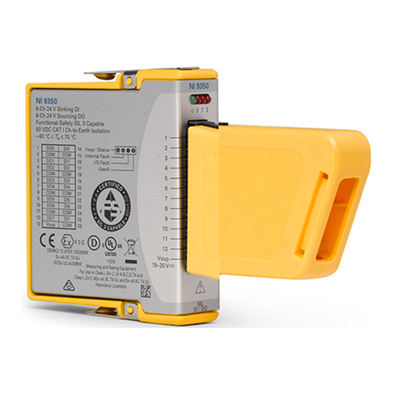
- Page 1 GETTING STARTED GUIDE NI 9350 8-Ch 24 V Sinking DI, 8-Ch 24 V Sourcing DO SIL3 Capable...
-
Page 2: Safety Guidelines
This document explains how to connect to the NI 9350. Before you begin, complete the software and Note hardware installation procedures in your chassis documentation. The guidelines in this document are specific to Note the NI 9350. The other components in the system might not meet the same safety ratings. -
Page 3: Safety Voltages
NI 9350. A hazardous voltage is a voltage greater than 42.4 V peak voltage or 60 V DC to earth ground. Maximum voltages -to-COM 30 V DC DI-to-COM 30 V DC DO-to-COM 0 V DC to V NI 9350 Getting Started Guide | © National Instruments | 3... - Page 4 Such voltage measurements include signal levels, special equipment, limited-energy parts of equipment, circuits powered by regulated low-voltage sources, and electronics. Channels include V and COM. 4 | ni.com | NI 9350 Getting Started Guide...
-
Page 5: Safety Guidelines For Hazardous Locations
Categories CAT II, CAT III, or CAT IV. Safety Guidelines for Hazardous Locations The NI 9350 is suitable for use in Class I, Division 2, Groups A, B, C, D, T4 hazardous locations; Class I, Zone 2, AEx nA IIC T4 Gc and Ex nA IIC T4 Gc hazardous locations;... -
Page 6: Special Conditions For Hazardous Locations Use In Europe And Internationally
II 3G and is suitable for use in Zone 2 hazardous locations, in ambient temperatures of -40 °C ≤ Ta ≤ 70 °C. If you are using the NI 9350 in Gas Group IIC hazardous locations, you must use the device in an NI chassis that has been evaluated as Ex nC IIC T4, Ex IIC T4, Ex nA IIC T4, or Ex nL IIC T4 equipment. -
Page 7: Electromagnetic Compatibility Guidelines
(EMC) stated in the product specifications. These requirements and limits provide reasonable protection against harmful interference when the product is operated in the intended operational electromagnetic environment. NI 9350 Getting Started Guide | © National Instruments | 7... -
Page 8: Special Conditions For Marine Applications
In order to meet the EMC requirements for Notice marine applications, install the product in a shielded enclosure with shielded and/or filtered power and input/output ports. In addition, take precautions when 8 | ni.com | NI 9350 Getting Started Guide... -
Page 9: Preparing The Environment
EMC performance is attained. Preparing the Environment Ensure that the environment in which you are using the NI 9350 meets the following specifications. Operating temperature -40 °C to 70 °C... - Page 10 NI 9350 Pinout Vsup 10 | ni.com | NI 9350 Getting Started Guide...
- Page 11 Table 1. Signal Descriptions Signal Description Common reference connection Digital input signal connection Digital output signal connection Voltage supply connection NI 9350 LEDs NI 9350 Getting Started Guide | © National Instruments | 11...
- Page 12 Table 2. LED Descriptions Description /Status Internal Fault I/O Fault UserLED0 12 | ni.com | NI 9350 Getting Started Guide...
- Page 13 Operational Mode or User Program is not running. Module is powered off. Flashing Module is in Fail-safe Mode. Internal Fault Module is not in Fail-safe Mode. NI 9350 Getting Started Guide | © National Instruments | 13...
- Page 14 I/O Fault No I/O Fault has been detected. UserLED0 Flashing User-configurable. Refer to the C Series Functional Safety Manual Note ni.com/manuals for detailed information on flash patterns in status and fault LEDs. 14 | ni.com | NI 9350 Getting Started Guide...
- Page 15 You must use the included connector Caution backshell to secure connections to the NI 9350. Figure 1. Connector Backshell Installation 1. Align the connector backshell with the 26-pin spring terminal block. NI 9350 Getting Started Guide | © National Instruments | 15...
-
Page 16: Connecting An External Power Supply
Tighten to 0.45 N · m (4 lb · in.) torque. Connecting an External Power Supply You must connect an external power supply to the NI 9350. The module is independent from the chassis and requires an external power supply to operate. - Page 17 Functional Safety Editor I/O Configurations Refer to the following diagrams to connect the NI 9350 based on the I/O configurations in the Functional Safety Editor. For more information about I/O Configurations, refer to the C Series Functional Safety Manual on ni.com/manuals.
- Page 18 Use this diagram for single input with test pulse configurations. • Use test pulses to detect wiring faults on NC (normally closed) switches. • Connect the DO pin to the NC (normally closed) switch to provide test pulse output. 18 | ni.com | NI 9350 Getting Started Guide...
- Page 19 NI 9350 Dual Input with Test Pulse Connection 3 kΩ (Optional) Device 3 kΩ (Optional) V sup External Power Supply – NI 9350 NI 9350 Getting Started Guide | © National Instruments | 19...
- Page 20 Use test pulses to detect wiring faults on NC (normally closed) switches. NI 9350 Output Connection Device – External Power Supply NI 9350 • Use this diagram for the following configurations: – Single output – Dual output 20 | ni.com | NI 9350 Getting Started Guide...
- Page 21 – Single output with internal test pulse – Dual output with internal test pulse NI 9350 Output with External Test Pulse Connection Device External – Power Supply NI 9350 NI 9350 Getting Started Guide | © National Instruments | 21...
- Page 22 Connect the DI channel number that corresponds to the DO channel number. Single output with test pulse connections use DOn and DIn. Dual output with test pulse connections use DOn and DIn, DOn+1 and DIn+1. 22 | ni.com | NI 9350 Getting Started Guide...
- Page 23 • Use this diagram for single output with external readback configurations. • Connect a wire from the external monitoring location to a DI channel to monitor the output value. NI 9350 Getting Started Guide | © National Instruments | 23...
- Page 24 NI 9350 Connection Guidelines • Make sure that devices you connect to the NI 9350 are compatible with the module specifications. • Connect one COM terminal for each DO and each DI connection until all COM terminals are populated. It is acceptable but not preferred to populate COM terminals with jumpers to meet this requirement.
-
Page 25: Power Supply
Resistor power must be rated at minimum to 300 mW at system ambient temperatures. A larger rating can increase reliability. • A pull-down resistor reduces input signal response times when channels are driven by sourcing outputs. NI 9350 Getting Started Guide | © National Instruments | 25... - Page 26 Third Party Manufacturer Series Phoenix Contact UTTB Weidmuller For more information on reducing response Note times, refer to the Safety Response Time section of the C Series Functional Safety Manual on ni.com/manuals. 26 | ni.com | NI 9350 Getting Started Guide...
- Page 27 Inductive or energy storing devices include solenoids, motors, and relays. Figure 2. Connecting a Flyback Diode to the NI 9350 Flyback Device Diode – External Power Supply NI 9350 NI 9350 Getting Started Guide | © National Instruments | 27...
-
Page 28: High-Vibration Application Connections
High-Vibration Application Connections If your application is subject to high vibration, NI recommends that you use ferrules to terminate stranded wire. You must follow these guidelines to meet the shock and vibration performance specifications stated in the device datasheet on ni.com/manuals. -
Page 29: Over Temperature Protection
Note for more information about I/O protection ratings. Overtemperature Protection The NI 9350 has an internal temperature sensor that will cause the module to enter Fail-safe Mode if the internal temperature limit is exceeded. Overtemperature protection will not cause the... -
Page 30: Where To Go Next
C Series Functional Safety Manual on ni.com/manuals. Worldwide Support and Services The NI website is your complete resource for technical support. At ni.com/support, you have access to everything from troubleshooting and application development self-help resources to email and phone assistance from NI Application Engineers. - Page 31 1 866 ASK MYNI (275 6964). For support outside the United States, visit the Worldwide Offices section of ni.com/ niglobal to access the branch office websites, which provide up- to-date contact information. NI 9350 Getting Started Guide | © National Instruments | 31...
- Page 32 . You can find information about end-user license agreements (EULAs) and third-party patents legal notices in the readme file for your NI product. Refer to the Export Compliance Information at for the NI global trade compliance policy and how to obtain ni.com/legal/export-compliance...
Need help?
Do you have a question about the 9350 and is the answer not in the manual?
Questions and answers