Table of Contents
Advertisement
Section 1__________________
General Description
The CX-12 is the latest generation multi-purpose
timer. It is designed to be versatile yet user friendly
with
easy
to
understand
adjustments. (It supersedes Model CX-11 Ultra)
Used as a make/break relay (or Switching Network) it
eliminates the binding of locked automatic doors, by
delaying the door operator until the strike or
electromagnet (de) activates first.
A new feature of this model is the ability to select one
of 4 Modes of operation – momentary; maintained
with Relay 1 held; maintained with Relay 2 held; and
bi-directional door sequencing (
In the Momentary position, even a stuck switch input
will allow the door to time out and close, thereby
providing security to occupants.
however, still operate normally if one of the other
inputs is activated. Essentially, it ignores the faulty
activation source, as all inputs are isolated.
The inputs to the CX-12 may be either dry or wet
(powered), meaning that 3-terminal radio receivers
may be connected directly to the CX-12 without fear
of malfunction.
SEE DIAGRAM 01
Additionally, we provide a direct connection from an
apartment interphone panel. Only Relay #1 (strike)
will operate when a voltage is applied to this input. A
vestibule courtesy switch will be energized for the
time set by Pot. 1.
SEE DIAGRAM 03 a or b.
Select Relay 1 Maintained for an Access Control
application. When a maintained signal is applied to
input, the lock will remain energized, while the
WET 1
input allows a wall switch to open the door. An
DRY 2
input on
will always unlock and open the door.
DRY 1
SEE DIAGRAM 02b.
Select Relay 2 Maintained if you are connecting the
CX-12 to a fire alarm panel, or to a presence sensor.
In this mode the lock will fire momentarily but the
operator relay will be held in as long as the input is
maintained.
SEE DIAGRAM 02a.
terminology
and
.
SEE DIAGRAM 04)
The CX-12 will
.
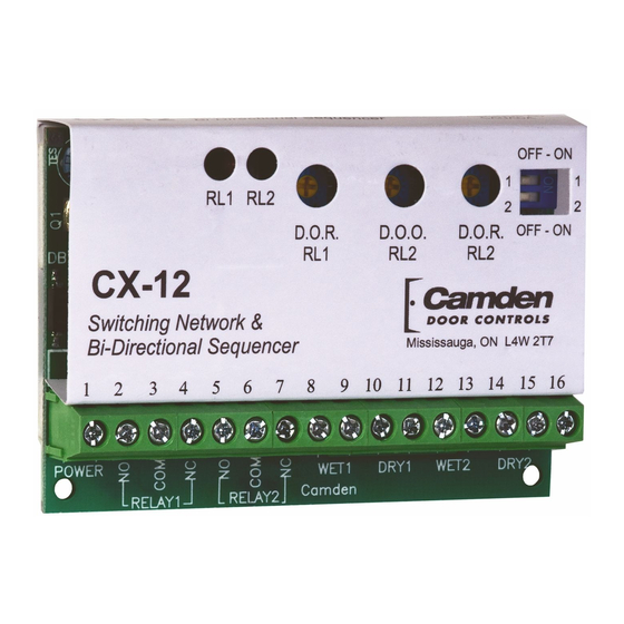
CX-12 Switching Network
& Bi-Directional Door Sequencer
Installation Instructions
For latching (ratchet or alternate action) functions, we
recommend our Model CX-1000/78 multi-purpose
timer, or Model SA-1 Switching Network.
IMPORTANT: Do not apply power to the unit until
you have read the instructions fully and made the
required adjustments.
Section 2__________________
Installation
Mounting
The LED's are visible through the wrap-around
sleeve, which also has cutouts for adjusting the
potentiometers, and setting the dip-switch. Once the
unit has been adjusted, it may be tucked up into the
operator header or affixed using the supplied Velcro.
Wiring
Wiring of this unit is dependent on the mode desired,
however
the
following
Note: Do not wire Safety devices to the CX-12.
If installed, wire your safety device directly to the
operator control box as per usual.
CAUTION: Do not apply power to the unit until all
secondary wiring is complete, and dip-switches have
been set.
Both relay outputs are Form C and are rated at 3
amps maximum. Use relay # 1 for the strike or
electromagnet. Generally the N.O. & COM. terminals
(#3 & 4) are used for a strike, and COM & N.C. (#4 &
5) are used with an electromagnet.
The door operator will be wired to relay #2
terminals (#6 & 7).
COM
application, door 1 is relay #1, and door 2 is relay #2.
The unit will operate on 12 or 24 volts, AC or DC.
Connect to Terminals 1 & 2, which are non-polarity
sensitive.
commonalities
apply.
N.O. &
In a door sequencing
Page 1 of 10
Advertisement
Table of Contents

Summary of Contents for CAMDEN CX-12
- Page 1 The inputs to the CX-12 may be either dry or wet (powered), meaning that 3-terminal radio receivers Note: Do not wire Safety devices to the CX-12. may be connected directly to the CX-12 without fear If installed, wire your safety device directly to the of malfunction.
- Page 2 In this case adjust the A device with a dry output such as a Presence CX-12 to send just a momentary pulse (1 or 2 sensor will connect to DRY 1 (Terminals 13 & 14). seconds only).
- Page 3 Camden Door Controls guarantees the CX-12 to be free from manufacturing defects for 3 years from date of sale. If during the first 3 years the CX-12 fails to perform correctly, it may be returned to our factory where it will be repaired or replaced (at our discretion) without charge.
- Page 5 5502 Timberlea Blvd. Camden Manufacturing Mississauga, Ontario L4W 2T7 Wire MOV (supplied) SCALE: NONE DRAWN BY: DGW DATE: 11/16/09 REVISED: directly to strike or magnet Power CX-12 Application Diagram (typical Momentary Operation) for Strike FILENAME: CX_12 Diagram 1.vsd DRAWING No: DRG-CX-12-01...
- Page 6 5502 Timberlea Blvd. Camden Manufacturing Mississauga, Ontario L4W 2T7 Wire MOV (supplied) SCALE: NONE DRAWN BY: DGW DATE: 11/16/09 REVISED: directly to strike or magnet Power CX-12 Application Diagram (with Maintained Operator output) for Strike FILENAME: CX_12 Diagram 2a.vsd DRAWING No: DRG-CX12-02a...
- Page 7 5502 Timberlea Blvd. Camden Manufacturing Mississauga, Ontario L4W 2T7 Wire MOV (supplied) SCALE: NONE DRAWN BY: DGW DATE: 11/16/09 REVISED: directly to strike or magnet Power CX-12 Application Diagram (with Maintained Lock Output) for Strike FILENAME: CX_12 Diagram 2b.vsd DRAWING No: DRG-CX12-02b...
- Page 8 5502 Timberlea Blvd. Camden Manufacturing Mississauga, Ontario L4W 2T7 Wire MOV (supplied) SCALE: NONE DRAWN BY: DGW DATE: 11/16/09 REVISED: directly to strike or magnet Power CX-12 Application Diagram for Apartment (typical) for Strike FILENAME: CX_12 Diagram 3a.vsd DRAWING No: DRG-CX12-03a...
- Page 9 Camden Manufacturing Mississauga, Ontario L4W 2T7 Wire MOV (supplied) SCALE: NONE DRAWN BY: DGW DATE: 11/16/09 REVISED: directly to strike or magnet Power CX-12 Application Diagram for Apt. (with Vestibule Keyswitch) for Strike FILENAME: DRAWING No: DRG-CX12-03b CX_12 Diagram 3b.vsd...
- Page 10 5502 Timberlea Blvd Camden Door Controls ie - RF Mississauga, Ontario receiver L4W 2T7 Door #1 (optional) Push SCALE: NONE DRAWN BY: DGW DATE: 11/16/09 REVISED: Switch CX-12 Application Diagram (Bi-Directional Sequencer operation) FILENAME: CX_12 Diagram 4.vsd DRAWING No: DRG-CX-12-04...
Need help?
Do you have a question about the CX-12 and is the answer not in the manual?
Questions and answers