Table of Contents
Advertisement
Quick Links
Advertisement
Table of Contents

Subscribe to Our Youtube Channel
Related Manuals for Laguna Tools CL1200


Summary of Contents for Laguna Tools CL1200
- Page 1 CL1200 LATHE MT0CL1200 MANUAL LAGUNA TOOLS 2072 Alton Parkway Irvine, California 92606 Ph: 800.234.1976 www.lagunatools.com © 2018, Laguna Tools, Inc. LAGUNA® and the LAGUNA Logo® are the registered trademarks of Laguna Tools, Inc. All rights reserved.
- Page 2 Machines sold through dealers must be registered with Laguna Tools within 30 days of purchase to be covered by this warranty. Laguna Tools guarantees all new machines and accessories sold to be free of manufacturers’...
-
Page 3: Table Of Contents
Table of contents Safety Rules Noise emission Specification sheet Accessories Receiving your machine Unpacking your lathe Introduction to lathes Parts of the lathe Assembly and setup Where to locate your lathe Assembling your lathe Operating your lathe Maintenance Troubleshooting Accessories Electrical drawing Spare parts Exploded view drawings and parts lists... -
Page 4: Safety Rules
Safety Rules As with all machinery there are certain hazards involved with the operation and use. Using machines with caution will considerably lessen the possibility of personal injury. However, if normal safety precautions are overlooked or ignored, personal injury to the operator may result. If you have any questions relative to the installation and operation, do not use the equipment until you have contacted your supplying distributor. -
Page 5: Noise Emission
Noise emission Notes concerning noise emission: Given that there exists a relationship between noise level and exposure times, it is not precise enough to determine the need for supplementary precautions. The factors affecting the true level of exposure to operators are clearly the amount of time exposed, the characteristics of the working environment, other sources of dust and noise, etc. -
Page 6: Accessories
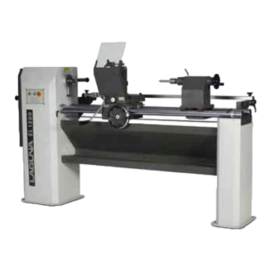
Cone of the tailstock barrel Spindle r.p.m. 500 /1000 / 2000 /2800 Motor output [1.5hp] Overall dimensions: Length 2105 [82.9”] Height 1225 [48.2”] Width 1000 [39.4”] Required area 2500/1800 [98’4”/70.8”] Mass, net 380 [836lb] Accessories Follow rest Range is from ø20 to ø120 mm Steady rest Range is from 10 to 108 mm Chuck ø16... -
Page 7: Receiving Your Machine
You must then contact the seller [Laguna Tools] as soon as practical. If you find damage after the driver has left, contact the seller [Laguna Tools] as soon as practical. -
Page 8: Parts Of The Lathe
Introduction to your lathe This lathe is designed to give you years of safe service. Please read this owner’s manual in its entirety before assembly. Parts of the lathe Body of the lathe The body is of welded construction, manufactured from heavy steel plate. It has three main parts: headstock, guide rails and a tail pillar. - Page 9 Electrical system The electrical system comprises of the following: A switch panel is mounted on the headstock that has the start, stop and emergency stop switch. Mounted behind the panel is the magnetic contactor. The motor is protected by an over-temperature switch [internal to the motor].
-
Page 10: Assembly And Setup
A tool rest is supplied which is mounted to the copy saddle and is adjustable for the height and diameter of the job. An optional guide-rail mounted tool rest is available from Laguna Tools. Identification There is a plate at the back of the machine listing all the manufacturing data including the serial number and model, etc. -
Page 11: Assembling Your Lathe
lathe and could cause the machine to vibrate. It is also recommended that the machine be mounted on anti-vibration material. When leveling the machine that is not bolted to the floor, insert the leveling bolts into the corner holes and adjust the bolts so that the machine is level in both planes and does not rock on the floor. -
Page 12: Operating Your Lathe
Operating your lathe Stop knob. Press to stop the machine, non-emergency operation. Green knob. Press to start the machine. Emergency stop knob, [red]. Press for emergency stop. To reset, turn clockwise. The machine will not operate until the switch has been reset. Machine test Now it is the time to test the machine. - Page 13 tensioned after running the machine for a few hours as the belt will bed into the pulleys. Note: With the power disconnected from the machine. Rotate handle and the motor will move in a vertical direction. This will slacken the belt. Move the belt to the selected set of pulleys.
- Page 14 An optional guide- rail mounted tool rest holder is available from Laguna tools. Tailstock The machine is supplied with a tailstock that can be adjusted along the guide rails of the lathe.
- Page 15 Also take care that they are not damaged while disassembling the rotating steady from the saddle. Align the spring pins to the holes in the saddle. Gently tap the casting so that the spring pins go into the holes and the casting is flush with the mating face.
- Page 16 selected. It has two bolts/nuts that clamp the housing in position and an adjusting knob. The tool is clamped in position by two Allen screws. Selecting a support bushing in the rotating steady The rotating steady has a number of bushings that support jobs of various sizes. Select a ring that is the next size up from the biggest diameter of the job.
- Page 17 Fitting the indexing mechanism Fit the indexing pin assembly at the back of the lathe with the screws provided. Lock the spindle with the spindle-locking rod [directly below the spindle thread]. The index plate has a split thread that is adjusted with a clamp screw.
- Page 18 To fit the router holder, remove the copy-cross slide tool holder, guard and rotating steady. Fit the router holder in the same hole group as the tool holder. Select the set of holes to suit the position you require. Copy turning Assembling the template holder The template or master holder is located at the back of the lathe.
- Page 19 has 3 tensions and is accessed from under the cross slide at the back of the machine. [Item 26: exploded view drawing of transversal support] The spring clips onto hooks. You should always use the strongest spring tension that the template or master can take without damage.
-
Page 20: Maintenance
of the center in front of the saddle cutting tool. Measure the distance between the center point and the cutting point of the tool and adjust using the slide limiting travel knob. Move the saddle so that the copy follower roller is in front of the largest diameter of the job. -
Page 21: Troubleshooting
Rust The lathe made from steel and cast iron. All non-painted surfaces will rust if not protected. It is recommended that non-painted surfaces be protected, by applying wax or a Teflon-based lubricant. Copy saddle chain adjustment The chain that controls the lateral movement of the saddle comes factory set and should not need adjustment. -
Page 22: Electrical Drawing
reset automatically. If the motor overheats, wait until it has cooled and restart. If the motor shuts down consistently, check for the reason. Typical reasons are dull cutting tools, motor-cooling fan clogged or faulty, motor-cooling fins clogged, over- feeding the job and excessive ambient temperature. Squeaking noise Check that the motor-cooling fan is not contacting the fan cover. -
Page 24: Spare Parts
Part description: Motor drive pulley. Part number: CL.00.06.00.04 Quantity: 1 piece Accessories The following accessories are available from Laguna Tools. Guide rail mounted tool rest. Large tool rest. Spare cutting tools. Work benches. Tool cabinet [wall mounted]. Tool cabinet [floor standing]. - Page 25 CL.00.00.00.00 BODY CL.00.00.00.10 STAND BDS 1234-85 BSS 1230-85 BDS 744-83 NUT М10 GN5337.2-50-M8-E STAR HANDLE 50 М8 DIN 471 SHAFT RING 8 CL.00.00.00.17 STUD BDS 206-78 WASHER АМ 8 CL 00.00.04.05 COVER BDS 206-78 WASHER АМ 6 BDS 744-83 NUT М6 ISO 7380 SCREW М6Х16 BDS 833-82...
- Page 26 CL.01.00.00.00 LONGITUDINAL SUPPORT...
- Page 27 CL.01.00.00.00 LONGITUDINAL SUPPORT CL.01.00.00.46 LONGITUDINAL SUPPORT CL.01.00.00.06 STAND DIN 555 NUT М10 DIN 551 FIXING SCREW М10Х25 CL.01.00.00.03 SLIDER DIN 913 FIXING SCREW М 8Х10 CL.01.00.00.09 REAR CAP DIN 915 FIXING SCREW М 8Х12 DIN 472 RING FOR HOLE 35 10 CL.01.00.00.27 LONG AXLE 11 CL.01.00.00.28...
- Page 28 CL.02.00.00.00 TRANSVERSAL SUPPORT GN736.1-52-Z10-A-S MEASURED HANDLE CL.02.00.00.16 SCREW CL.02.00.00.10 TRANSVERSAL SUPPORT...
- Page 29 DIN 551 FIXING SCREW М8Х10 BDS 833-82 SPRING WASHER 2- 6H BDS 2171-83 SCREW М 6X25 BDS 2171-83 SCREW М8Х25 BDS 2171-83 SCREW М8Х20 CL.02.11.01.00 CUTTER HOLDER CL.02.01.00.07 DELIMITATION NUT CL.02.01.05.00 GUIDE BDS 206-78 WASHER АМ 8 ISO 7380 SCREW М 8Х25 PM 625 STAR HANDLE 25М6x16 CL.02.01.00.04...
- Page 30 CL.00.03.00.00 PATTERN HOLDER GN5337.2-50-M8-E STAR HANDLE 50 М8 BDS 206-78 WASHER АМ 10 CL.00.03.00.11 SCREW CL.00.03.00.10 AXLE DIN 985 NUT М 10 BDS 206-78 WASHER АМ 8 BDS 1234-85 BOLT М10Х35 GN603-63-М8-25-DGN HANDLE М8Х25 CL.00.03.00.28 COTTER CL.00.03.05.00 REAR CONSOLE PLUG FOR TUBE 40x30x3 CL.00.03.00.27 STUD GN5337.2-63-M10-E...
- Page 31 CL.00.03.00.21 UPPER PLATE BDS 833-82 SPRING WASHER 2- 6H BDS 2171-83 SCREW М 6X25 BDS 2171-83 SCREW М 6Х35 CL.00.03.00.16 UPPER CLAMP CL.00.03.00.15 MEDIAL PLATE DIN 913 FIXING SCREW М 6Х20 CL.00.03.01.00 FRONT CONSOLE BDS 1234-85 BOLT М10 Х25...
- Page 32 CL.00.06.00.00 MAIN GEAR UN 9139 ROUND NUT M25X1.5 CL.00.06.00.16 DRIVEN PULLEY BALL RADIAL BEARING 6206- CL.00.06.00.20 FRONT SEAT CL.00.06.00.13 SUPPORT BDS 744-83 NUT М10 DIN 6885A STUD 8Х7Х40 CL.00.06.00.19 SPINDLE...
- Page 33 CL.00.06.00.25 ROUND NUT WITH SLOTS BALL RADIAL BEARING 6208- CL.00.06.00.46 PRESSING PLUG CL.00.06.00.27 EXTERNAL FLANGE BDS 833-82 SPRING WASHER 2-8Н BDS 2171-83 SCREW М 8Х40 DIN 913 FIXING SCREW М 8Х25 CL.00.06.00.29 SPRING DIN 471 SHAFT RING 8 CL.00.06.00.31 GUIDE CL.00.06.00.32 REST DIN 319-KU-25-M8-C...
- Page 34 CL.00.06.09.05 CL.00.06.11.01 HINGED BOLT CL.00.06.09.04 BLOCK DIN 1481 SPRING PIN Ф 5Х20 CL.00.06.09.01 LEVER CL.00.06.00.36 GUIDE CL.00.06.00.45 GUIDING SUPPORT BDS 2171-83 SCREW М10Х30 CL.08.00.00.00 TAILSTOCK CL.08.00.00.25 TIGHTENING PLATE BDS 744-83 NUT М16 CL.08.00.00.18 STUD М16 BDS 1359-83 SCREW М 5 х16 CL.07.02.00.15 PAD I CL.07.02.00.01 PAD II CL.08.04.00.00 SHELL...
- Page 35 BDS 206-78 WASHER АМ16 DIN 985 NUT М16 BDS 2171-83 SCREW М 6Х30 DIN 472 RING FOR HOLE 35 BALL RADIAL BEARING 6202-ZZ CL.08.00.00.07 BEARING BOX ISO 7380 SCREW М 6Х30 CL.08.00.00.11 FLYWHEEL Ф120 UN 732 WASHER Ф 6ХФ25Х1,8 ISO 7380 SCREW М6Х16 BDS 2171-83 SCREW М...
- Page 36 CL.07.01.00.00 FOLLOW REST Ф120 СL.07.01.00.11 CARRIER BDS 833-82 SPRING WASHER 2-10Н DIN 6912 SCREW М10Х30 BDS 833-82 SPRING WASHER 2-8Н BDS 2171-83 SCREW М 8Х60 СL.07.01.00.12 PLATE FOR Ф120 BDS 2171-83 SCREW М8Х25 DIN 1481 SPRING PIN Ф 6Х30 СL.07.01.18.05 RING Ф20 СL.07.01.18.04 RING Ф40...
- Page 37 СL.07.01.00.01 STUD FOR Ф120 23 СL.07.01.00.24 FOLLOW REST FOR Ф120 24 DIN 985 NUT М 12 25 BDS 206-78 WASHER АМ12 26 DIN 913 FIXING SCREW М 6Х10 BALL RADIAL BEARING 6024-ZZ 28 DIN 439 LOW NUT М12 29 GN5330-80-М10-E Р HANDLE 30 СL.07.01.18.01 RING Ф100...
- Page 38 CL.07.02.00.00 STEADY REST BDS 2171-83 SCREW М 6Х20 BDS 833-82 SPRING WASHER 2- 6H CL.07.02.00.19 PLATE I CL.07.02.00.01 PAD II BDS 744-83 NUT М10 CL.07.02.00.15 PAD I BDS 1359-83 SCREW М 5Х20 CL.07.02.00.17 STUD М10 CL.07.02.14.00 STAND 10 BDS 206-78 WASHER АМ...
- Page 39 GN5337.2-40-M8- STAR HANDLE 40 М8X20 16 ISO 7380 SCREW М 8Х20 BALL RADIAL BEARING 628-2RS 18 BDS 833-82 SPRING WASHER 2-8Н CL.07.03.00.00 HAND CUTTER HOLDER CL.07.03.03.00 HOLDER BDS 2171-83 SCREW М 8Х35 DIN 134 WASHER M 8 CL.07.03.01.00 SUPPORT GN603-63-М8-20- HANDLE М8Х20...
- Page 40 CL.07.04.00.00 UNIVERSAL DISK Ø200 CL.07.04.01.00 UNIVERSAL DISK DIN 913 FIXING SCREW М6Х8 CL.07.04.00.02 NUT PLUG М33Х3.5 BDS 664-82 SCREW FOR WOOD 6Х35...
- Page 41 CL.07.05.00.00 MILLING-SPLITTING ADAPTOR BDS 2171-83 SCREW М 8Х30 BDS 833-82 SPRING WASHER 2-8Н CL.07.05.01.00 SPLITTING DISK CL.07.05.04.00 FIXING DEVICE GN5337.2-50-M10- STAR HANDLE 50 М10 CL.07.05.00.15 STUD CL.07.05.03.00 SHELL DIN 915 FIXING SCREW М10Х16 CL.07.05.00.04 COLUMN 10 CL.07.05.02.00 CLAMP 11 BDS 2171-83 SCREW М...
- Page 42 CL.07.06.00.00 PROTECTED SCREEN CL.07.06.01.00 SCREEN CARRIER CL.07.06.00.02 SCREEN PM 625 STAR HANDLE 25 М6x16...
- Page 43 CL.07.17.00.00 ROTATION CENTRE МК2-Ф20 CL.07.17.00.03 SHELL DIN 471 SHAFT RING 15 BALL RADIAL BEARING 6202-ZZ CL.07.17.00.06 BUSHING DIN 472 RING FOR HOLE 35 CL.07.17.00.01 CENTRE...
- Page 44 OTHER ACCESSORIES CL.07.08.00.00 SERRATED DRIVE CENTRE Ф20 CL.07.00.00.16 ROTATION CENTRE МК Ф40 CL.07.00.00.11 SERRATED DRIVE CENTRE Ф40 CL.07.00.00.18 SCOURING CUTTER 16х16 CL.07.00.00.12 'V'-SHAPED CUTTER...
- Page 45 Laguna Tools is not responsible for errors or omissions. Specifications subject to change. Machines may be shown with optional accessories. © 2018, Laguna Tools, Inc. LAGUNA® and the LAGUNA Logo® are the registered trademarks of Laguna Tools, Inc. All rights reserved.
Need help?
Do you have a question about the CL1200 and is the answer not in the manual?
Questions and answers